Output Devices
Interfacing an Output Device
For this assignment, I used:
- ESP8266 (NodeMCU)
- I2C LCD (16×2)
- FT232RL USB to Serial adapter
- Breadboard
- Jumper wires
- Wanptek NPS1203W laboratory power supply
- Computer with Arduino IDE
Hardware Connections
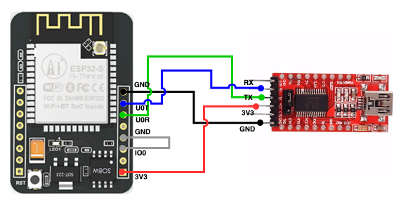
FT232RL Connections to ESP8266
I used the FT232RL USB-to-Serial adapter to upload the program to the ESP8266.
Connections:
- FT232RL GND → ESP8266 GND
- FT232RL 3V3 → ESP8266 3V3
- FT232RL TX → ESP8266 U0R (RX)
- FT232RL RX → ESP8266 U0T (TX)
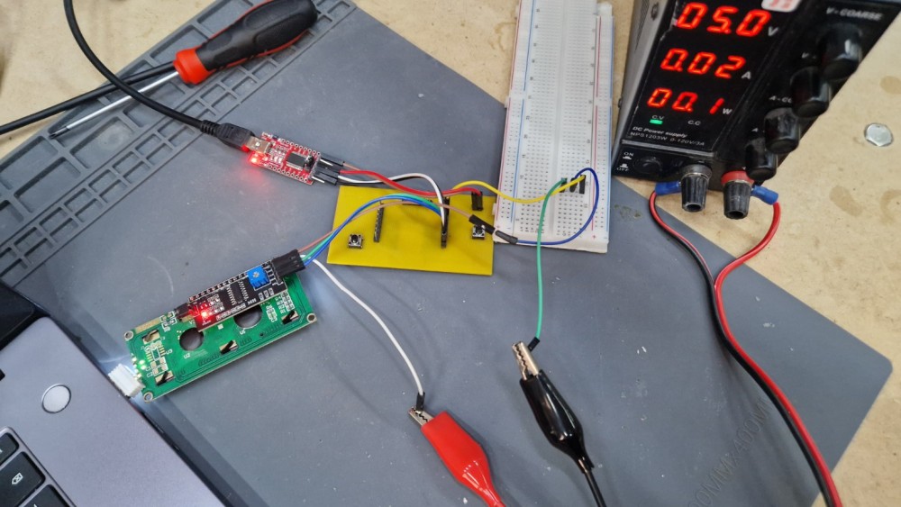
Power Supply
I used a Wanptek NPS1203W laboratory power supply and set the output voltage to 5 V.
Important: Do not exceed 5.5 V, because it may damage the LCD display or other electronic devices.
Connections:
- Power supply negative terminal → Breadboard GND
- Power supply positive terminal → LCD VCC
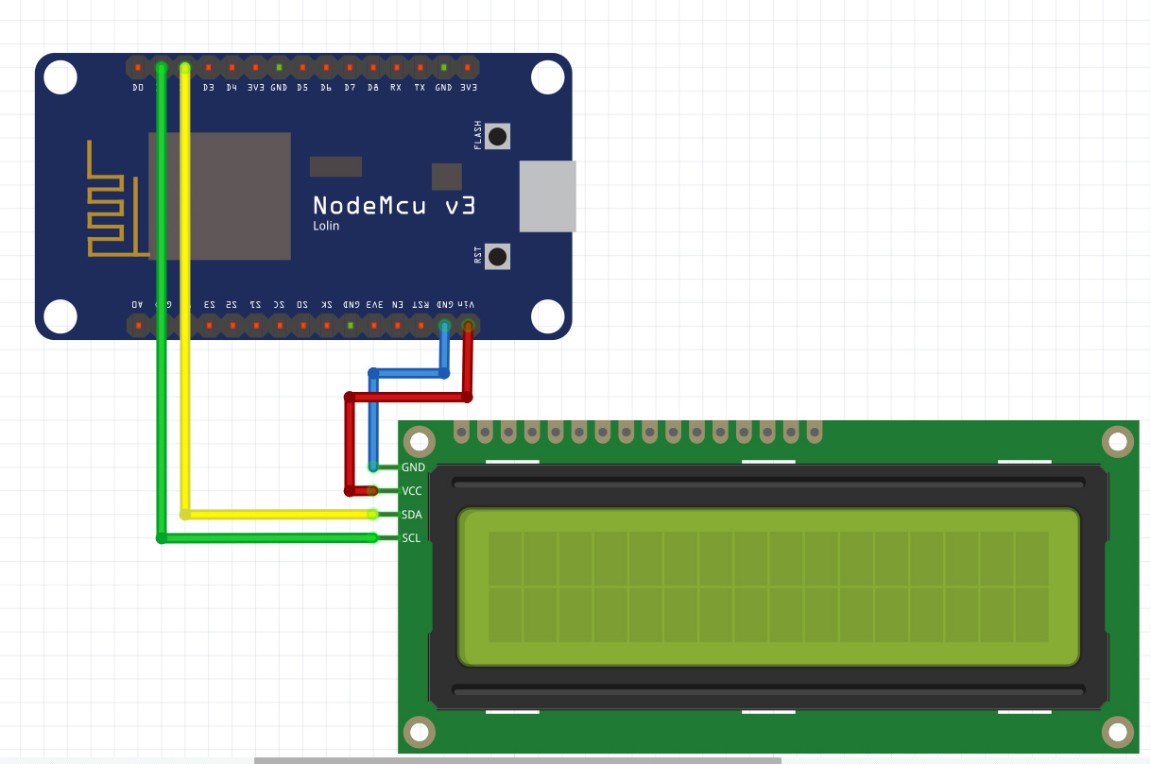
I2C LCD Connections
- LCD (I2C) → ESP8266 (NodeMCU)
- GND → GND
- VCC → 5 V (Wanptek NPS1203W)
- SDA → D2 (GPIO4)
- SCL → D1 (GPIO5)
Programming Process
I used the Wire and LiquidCrystal_I2C libraries.
First, I created an LCD object using the I2C address 0x27 and configured the display as a 16×2 LCD.
In the setup function:
- the LCD was initialized;
- the backlight was enabled;
- the cursor was positioned at the beginning of the first row;
- the text "Hello, World!" was displayed;
- the cursor was moved to the second row;
- the text "ESP8266 + LCD" was displayed.
The loop function remains empty because the display only needs to show a fixed message.
After uploading the code, the LCD displayed the text correctly.
Source Code
#include <Wire.h>
#include <LiquidCrystal_I2C.h>

LiquidCrystal_I2C lcd(0x27, 16, 2);

void setup() {
  lcd.init();
  lcd.backlight();

  lcd.setCursor(0, 0);
  lcd.print("Hello, World!");

  lcd.setCursor(0, 1);
  lcd.print("Hello, World!");
}

void loop() {
}
Code Explanation
#include <Wire.h>enables I2C communication.#include <LiquidCrystal_I2C.h>imports the LCD library.LiquidCrystal_I2C lcd(0x27, 16, 2);creates a 16×2 LCD object with I2C address 0x27.lcd.init();initializes the LCD display.lcd.backlight();turns on the LCD backlight.vlcd.setCursor(column, row);sets the cursor position.lcd.print();displays text on the LCD.loop()remains empty because the displayed text does not change
Problems Encountered and Solutions
While uploading the program, I encountered the following error:
avrdude: stk500_getsync() not in sync
The sketch could not be uploaded successfully.
Cause
The ESP8266 board package was not installed in Arduino IDE.
Solution
I fixed the problem by installing the ESP8266 package.
Steps
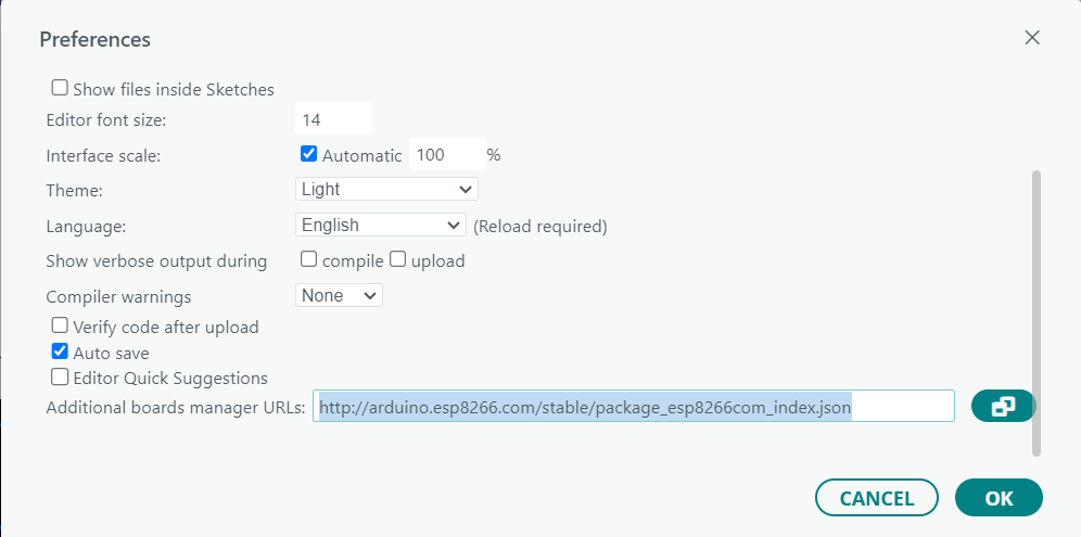
Open File → Preferences. In Additional Boards Manager URLs, add:
http://arduino.esp8266.com/stable/package_esp8266com_index.json
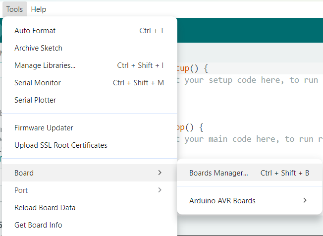
Open Tools → Board Manager.
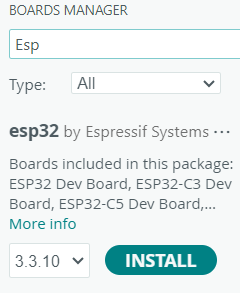
Search for ESP8266. Install the package.
After installing the ESP8266 package, the upload process worked correctly and the LCD displayed the text.