Networking and Communications
UART Communication (Arduino Uno ↔ ESP8266-12E)
Description
In this part of the project, I implemented UART communication between Arduino Uno and ESP8266-12E.
The goal was:
- Send data between devices
- Control LED using serial commands
- Test communication protocol
Hardware Connection
UART Wiring:
- Arduino TX → ESP RX (through voltage divider)
- Arduino RX ← ESP TX
- GND ↔ GND
Voltage Divider
- 1kΩ + 2kΩ resistors used
- Converts 5V → 3.3V
LED Connection (ESP8266)
- GPIO2 → resistor (220Ω) → LED → GND
Video Demonstration
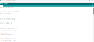
Code
Arduino Code (UART Bridge)
#include <SoftwareSerial.h>

SoftwareSerial esp(2, 3); // RX, TX

void setup() {
  Serial.begin(9600);
  esp.begin(9600);
}

void loop() {
  // PC → ESP
  if (Serial.available()) {
    esp.write(Serial.read());
  }

  // ESP → PC
  if (esp.available()) {
    Serial.write(esp.read());
  }
}
ESP8266 Code (LED Control via UART)
#define LED_PIN 2

String command = "";

void setup() {
  Serial.begin(9600);
  pinMode(LED_PIN, OUTPUT);
  digitalWrite(LED_PIN, LOW);
}

void loop() {
  while (Serial.available()) {
    char c = Serial.read();
    command += c;

    if (c == '\n') {
      command.trim();

      if (command == "ON") {
        digitalWrite(LED_PIN, HIGH);
        Serial.println("LED ON");
      }
      else if (command == "OFF") {
        digitalWrite(LED_PIN, LOW);
        Serial.println("LED OFF");
      }

      command = "";
    }
  }
}
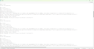
Testing
Steps:
-
Open Serial Monitor
-
Set:
-
Baud rate: 9600
-
Both NL & CR
-
Send commands:
ON
OFF
Result
- LED turns ON when
"ON"is sent - LED turns OFF when
"OFF"is sent - UART communication works correctly
ESP8266 Web Server (LED Control)
Description
In this part of the project, I created a web server using the ESP8266-12E module. The web server allows controlling two LEDs through a web browser using Wi-Fi.
The system uses the HTTP protocol to send commands from the client (browser) to the ESP8266.
Hardware Connection
LED Connections:
- GPIO5 (D1) → LED → 220Ω resistor → GND
- GPIO4 (D2) → LED → 220Ω resistor → GND
Power Supply:
- ESP8266 → 3.3V external power supply
- GND → common ground
The Arduino 3.3V pin is not sufficient for stable ESP8266 operation.
Hardware Setup (Hero Shot)
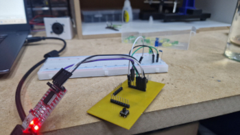
- Photo of ESP8266 with LEDs
- Wiring setup
 * Working LEDs
Demonstration
- Opening IP address in browser
- Clicking ON/OFF buttons
- LEDs turning ON/OFF
Code (ESP8266 Web Server)
#include <ESP8266WiFi.h>

// Replace with your WiFi credentials
const char* ssid = "YOUR_SSID";
const char* password = "YOUR_PASSWORD";

WiFiServer server(80);

String header;

String output5State = "off";
String output4State = "off";

const int output5 = 5;
const int output4 = 4;

void setup() {
  Serial.begin(115200);

  pinMode(output5, OUTPUT);
  pinMode(output4, OUTPUT);

  digitalWrite(output5, LOW);
  digitalWrite(output4, LOW);

  WiFi.begin(ssid, password);

  while (WiFi.status() != WL_CONNECTED) {
    delay(500);
    Serial.print(".");
  }

  Serial.println("\nWiFi connected");
  Serial.println(WiFi.localIP());

  server.begin();
}

void loop() {
  WiFiClient client = server.available();

  if (client) {
    String currentLine = "";

    while (client.connected()) {
      if (client.available()) {
        char c = client.read();
        header += c;

        if (c == '\n') {
          if (currentLine.length() == 0) {

            client.println("HTTP/1.1 200 OK");
            client.println("Content-type:text/html");
            client.println("Connection: close");
            client.println();

            // LED control
            if (header.indexOf("GET /5/on") >= 0) {
              digitalWrite(output5, HIGH);
              output5State = "on";
            } else if (header.indexOf("GET /5/off") >= 0) {
              digitalWrite(output5, LOW);
              output5State = "off";
            }

            if (header.indexOf("GET /4/on") >= 0) {
              digitalWrite(output4, HIGH);
              output4State = "on";
            } else if (header.indexOf("GET /4/off") >= 0) {
              digitalWrite(output4, LOW);
              output4State = "off";
            }

            // HTML page
            client.println("<html><body>");
            client.println("<h1>ESP8266 Web Server</h1>");

            client.println("<p>LED1</p>");
            client.println("<a href=\"/5/on\">ON</a>");
            client.println("<a href=\"/5/off\">OFF</a>");

            client.println("<p>LED2</p>");
            client.println("<a href=\"/4/on\">ON</a>");
            client.println("<a href=\"/4/off\">OFF</a>");

            client.println("</body></html>");

            client.println();
            break;
          } else {
            currentLine = "";
          }
        } else if (c != '\r') {
          currentLine += c;
        }
      }
    }

    header = "";
    client.stop();
  }
}
🧪 Testing
Steps:
- Upload code to ESP8266
-
Open Serial Monitor (115200 baud)
-
Copy the IP address
- Paste it into a web browser
Example:
http://192.168.1.100
Result
- Web page loads successfully
- Buttons control LEDs
- LED states update correctly