11 - Networking and Communications
Summary
This week was all about networks, we had to get familiar with workflows and networking and communication protocols.
Approach
Since I have quite a bit of coding experience this week was relatively easy. Most exciting part was getting to travel to Enschede and seeing Leo's lab <3
Assignment
- individual assignment:
- design, build, and connect wired or wireless node(s) with network or bus addresses and local input &/or output device(s)
- group assignment:
- send a message between two projects
Individual assignment
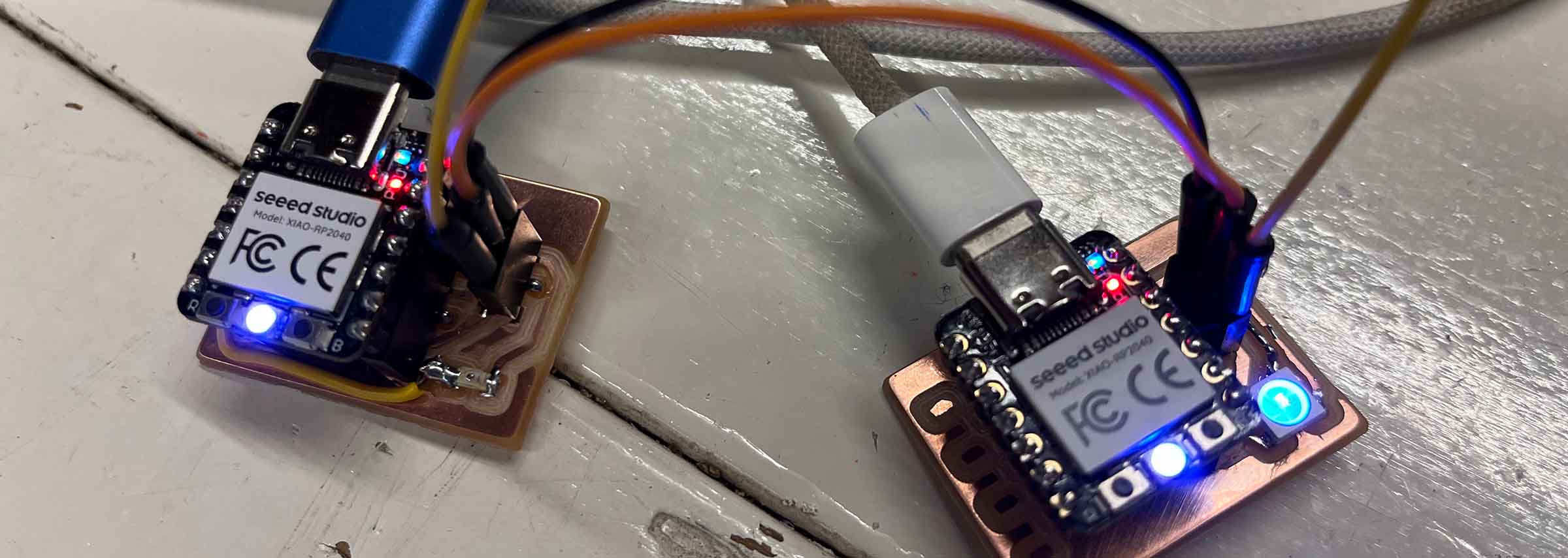
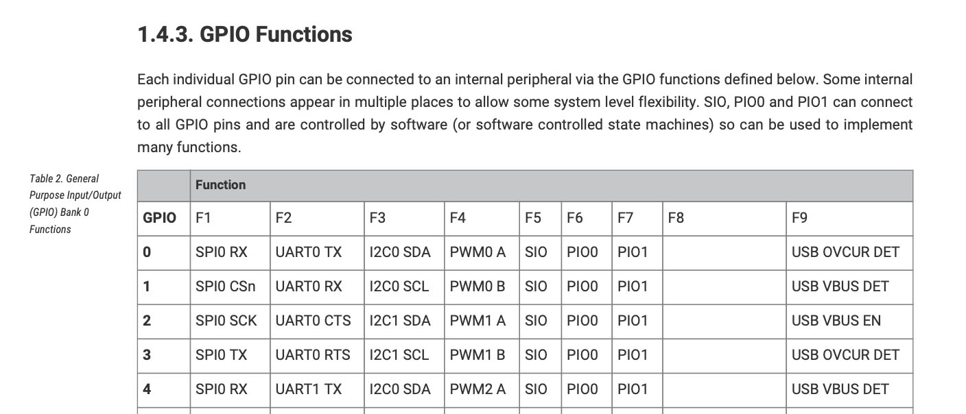
I made two nodes that can communicate through I2C, one with a phototransistor as an input and one with a Neopixel as an output. Both boards use the Xiao RP2040, used in previous weeks, as the microcontroller. For the I2C pins I used pin 2 and 3, following the datasheet, to give met I2C1 SDA and I2C1 SCL as peripherals (something I learned from the group assignment this week).
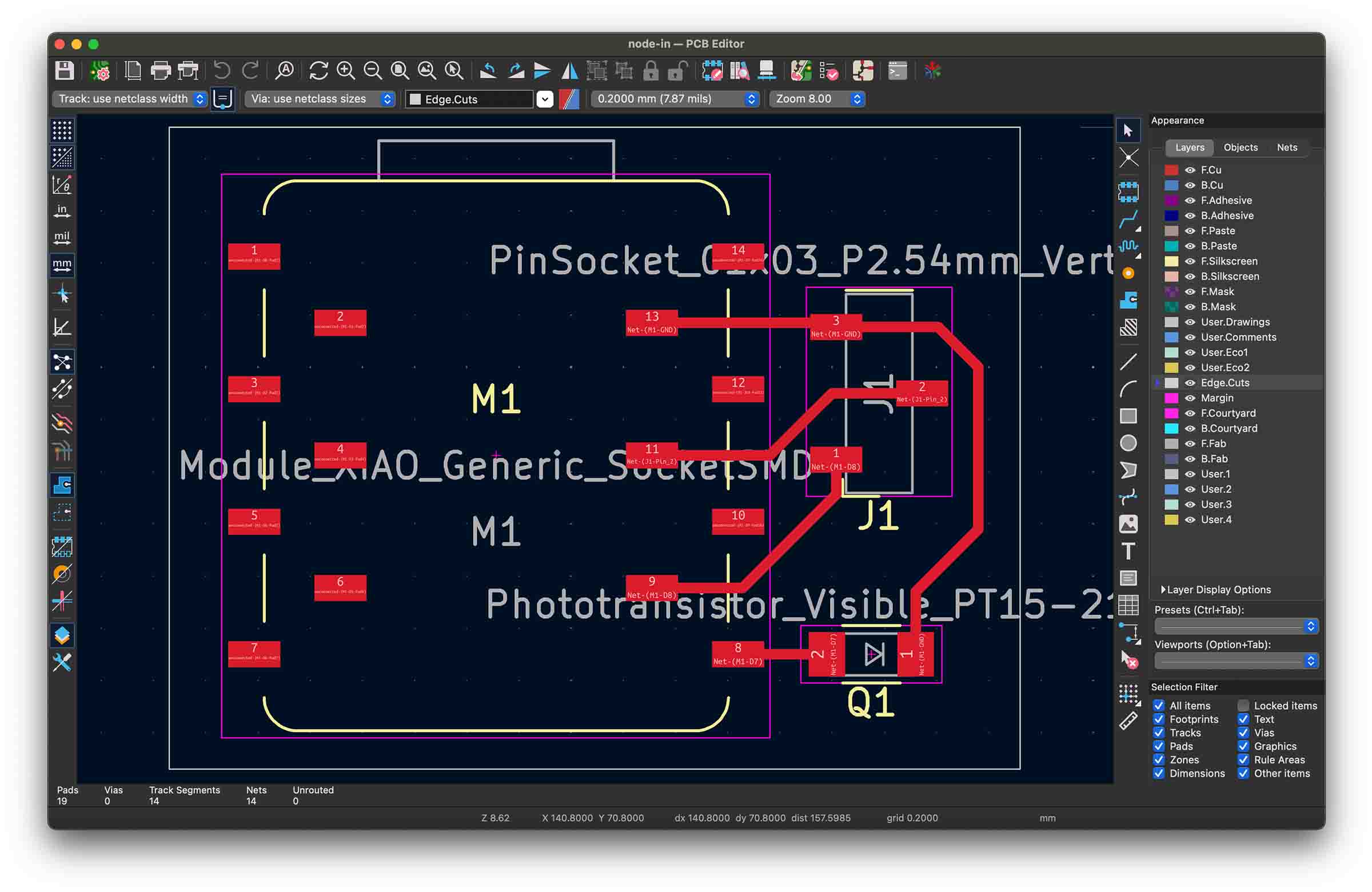 Input board
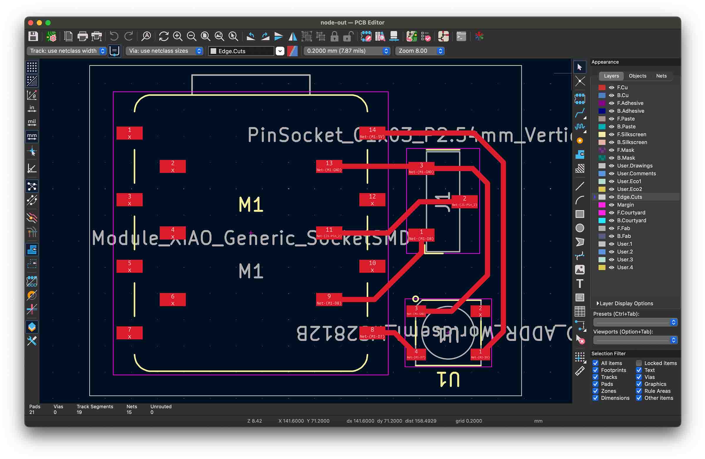 Output board
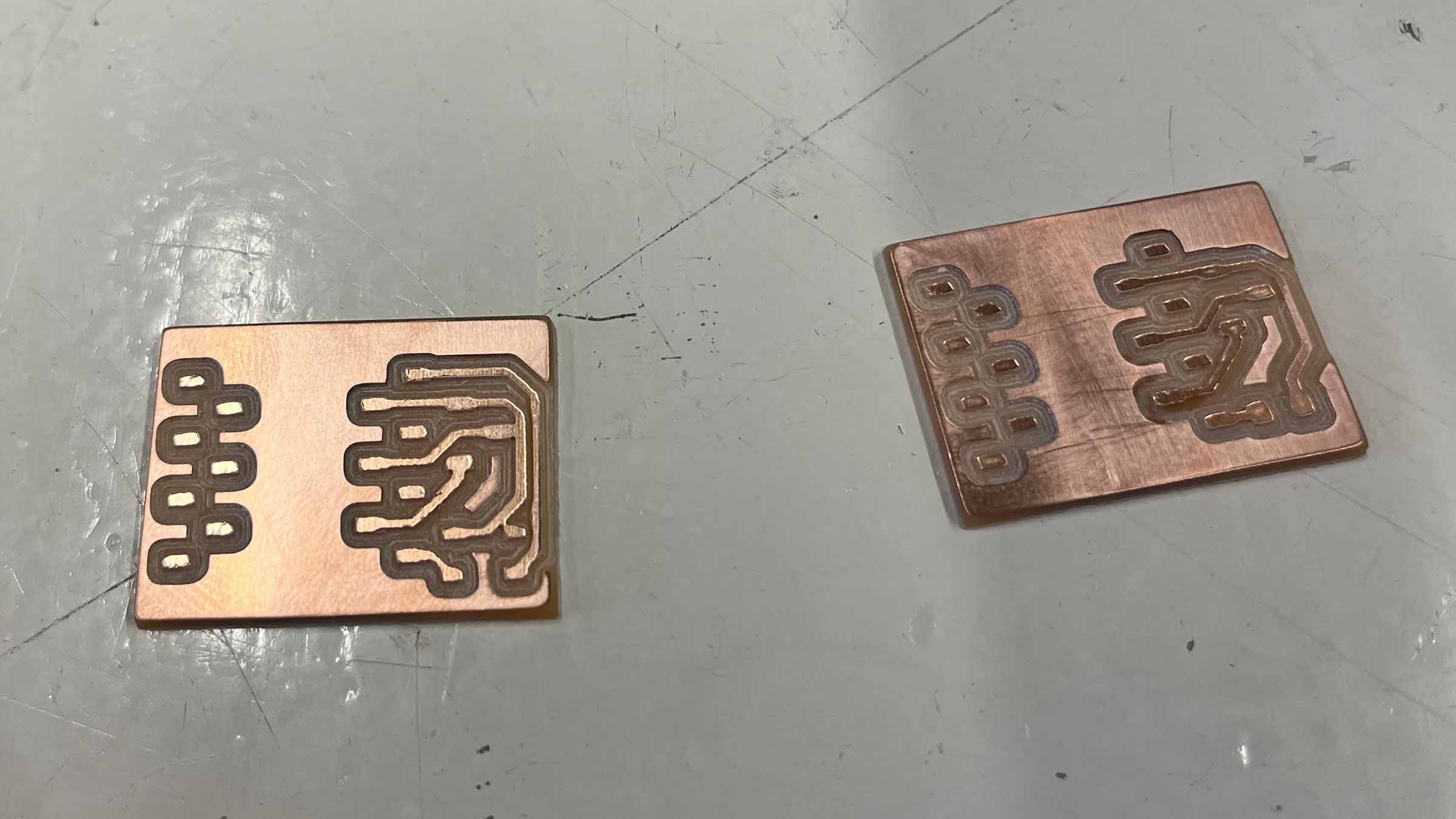
Two of my traces got fused because I inputted a 0.4 clearance in KiCad, but set the tool diameter to 0.6mm in Mods, this was something I had written down wrong following week 8's instructions. It makes sense to use 0.6mm when doing the edge cut, since you're going deeper, but it's not a good idea when doing the traces; from now on I'll use 0.4 in Mods as well.
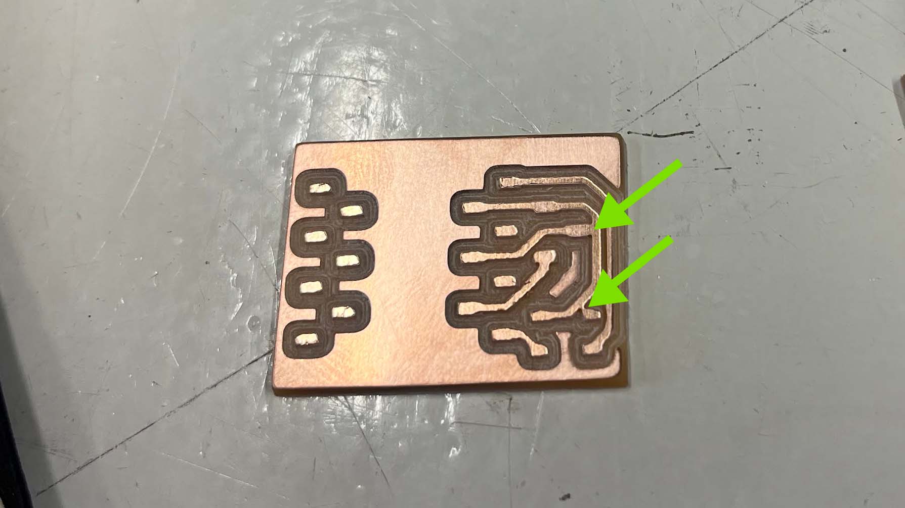
While cutting through these fused trace I accidentally severed one that didn't need separating, so I fixed that with a bit of solder. Then later on it turned out I had put the phototransistor, an analogue sensor, on a digital pin, so I had to bodge that with a little wire. They're not the prettiest PCB's, but everything is connected correctly!
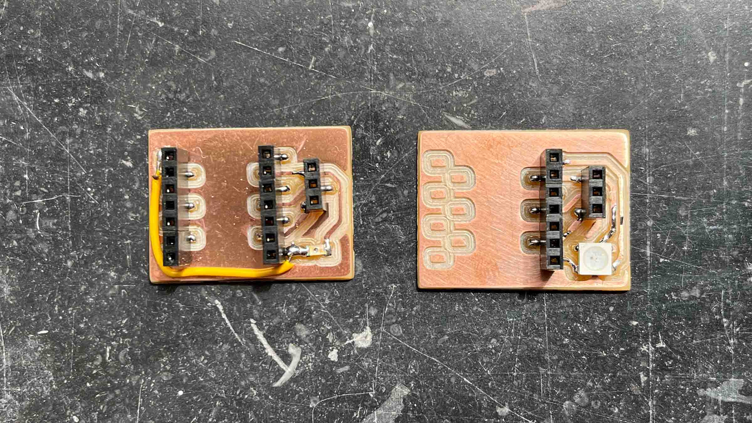
I start out by testing the phototransistor running some test code that ChatGPT wrote. The RP2040 microcontroller has a built-in 12-bit ADC (Analog-to-Digital Converter), meaning analog sensor values are converted into digital values ranging from 0 to 4095, so I'm expecting similar values, unfortunately I'm getting values in a range of 0 (brightest) to 60 (darkest). Turns out I should have added a resistor to the phototransistor's net. I ask ChatGTP to explain this to me.
A normal GPIO/ADC pin measures voltage. But a phototransistor naturally changes the amount of current flowing through it when light hits it. The resistor converts that changing current into a changing voltage that the ADC can actually measure.
Without the resistor: - the pin voltage is undefined/floating-ish - the phototransistor is basically just trying to dump current to GND - the ADC has nothing stable to measure
The resistor creates a “tug of war”: - resistor pulls the signal toward 3.3V - phototransistor pulls it toward GND - the balance between those creates a measurable voltage
That voltage is what becomes your ADC value.
I try to use an internal pull up resistor, but this is too weak, since this week is about networking, I can get some values I can work with and I understand where I went wrong and how to prevent this next time, I decide to move on. I ask ChatGPT for some example Neopixel code and luckily this board works as expected.
#include <Adafruit_NeoPixel.h>

#define LED_PIN 1      // D7 / GPIO1
#define NUM_PIXELS 1

Adafruit_NeoPixel pixel(NUM_PIXELS, LED_PIN, NEO_GRB + NEO_KHZ800);

void setup() {
  pixel.begin();
  pixel.setBrightness(50);

  pixel.clear();
  pixel.show();
}

void loop() {

  // RED
  pixel.setPixelColor(0, pixel.Color(255, 0, 0));
  pixel.show();
  delay(500);

  // GREEN
  pixel.setPixelColor(0, pixel.Color(0, 255, 0));
  pixel.show();
  delay(500);

  // BLUE
  pixel.setPixelColor(0, pixel.Color(0, 0, 255));
  pixel.show();
  delay(500);

  // OFF
  pixel.clear();
  pixel.show();
  delay(500);
}
It makes sense to me for the board with the phototransistor to be the master and only communicate color values over I2C. I also think it's nice if the internal Neopixels in the Xiaos correspond so I can see if master and slave are in sync. I ask ChatGPT to update the code with this logic and translate the color space to the phototransistor range I'm measuring (0-60). I was a bit behind on my homework this week, but we worked a lot with I2C in machine week, so even though I didn't write this code myself I feel like I have a good understanding of the protocol.
LED colors are hard to capture on video, but you should see a shift from red to blue
Master code
#include <Wire.h>
#include <Adafruit_NeoPixel.h>

// Phototransistor
#define SENSOR_PIN 26      // D0 / GPIO26 / ADC0

// Built-in XIAO RP2040 NeoPixel
#define NEOPIXEL_PWR 11
#define NEOPIXEL_PIN   12
#define NUM_PIXELS     1

// I2C
#define I2C_SDA_PIN 2          // D8
#define I2C_SCL_PIN 3          // D10
#define SLAVE_ADDR 0x42

Adafruit_NeoPixel pixel(NUM_PIXELS, NEOPIXEL_PIN, NEO_GRB + NEO_KHZ800);

void setup() {
  Serial.begin(115200);

  // ADC range: 0–4095
  analogReadResolution(12);

  // Turn on built-in NeoPixel power
  pinMode(NEOPIXEL_PWR, OUTPUT);
  digitalWrite(NEOPIXEL_PWR, HIGH);

  pixel.begin();
  pixel.setBrightness(50);
  pixel.clear();
  pixel.show();

  // I2C master setup
  Wire.setSDA(I2C_SDA_PIN);
  Wire.setSCL(I2C_SCL_PIN);
  Wire.begin();

  Serial.println("Master started");
}

void loop() {
  int sensorValue = analogRead(SENSOR_PIN);

  // Your phototransistor circuit:
  // dark  = high value
  // light = low value
  int brightness = map(sensorValue, 60, 20, 0, 255);
  brightness = constrain(brightness, 0, 255);

  // Debug color:
  // dark  = blue
  // light = red
  byte red   = brightness;
  byte green = 0;
  byte blue  = 255 - brightness;

  // Show color locally
  pixel.setPixelColor(0, pixel.Color(red, green, blue));
  pixel.show();

  // Send same color to slave over I2C
  Wire.beginTransmission(SLAVE_ADDR);
  Wire.write(red);
  Wire.write(green);
  Wire.write(blue);
  byte error = Wire.endTransmission();

  Serial.print("sensor: ");
  Serial.print(sensorValue);
  Serial.print(" | brightness: ");
  Serial.print(brightness);
  Serial.print(" | rgb: ");
  Serial.print(red);
  Serial.print(", ");
  Serial.print(green);
  Serial.print(", ");
  Serial.print(blue);
  Serial.print(" | i2c error: ");
  Serial.println(error);

  delay(50);
}
Slave code
#include <Wire.h>
#include <Adafruit_NeoPixel.h>

// ---------- Built-in NeoPixel ----------
#define BUILTIN_POWER 11
#define BUILTIN_PIN   12

// ---------- External NeoPixel ----------
#define EXTERNAL_PIN  1   // D7 / GPIO1

#define NUM_PIXELS 1

// ---------- I2C ----------
#define I2C_SDA_PIN 2         // D8
#define I2C_SCL_PIN 3         // D10
#define I2C_ADDR 0x42

Adafruit_NeoPixel builtInPixel(NUM_PIXELS, BUILTIN_PIN, NEO_GRB + NEO_KHZ800);
Adafruit_NeoPixel externalPixel(NUM_PIXELS, EXTERNAL_PIN, NEO_GRB + NEO_KHZ800);

volatile byte redValue = 0;
volatile byte greenValue = 0;
volatile byte blueValue = 0;

volatile bool newColor = false;

void receiveEvent(int howMany) {
  if (howMany >= 3) {
    redValue = Wire.read();
    greenValue = Wire.read();
    blueValue = Wire.read();

    newColor = true;
  }

  while (Wire.available()) {
    Wire.read();
  }
}

void setup() {
  Serial.begin(115200);

  // Enable built-in NeoPixel power
  pinMode(BUILTIN_POWER, OUTPUT);
  digitalWrite(BUILTIN_POWER, HIGH);

  // Init built-in pixel
  builtInPixel.begin();
  builtInPixel.setBrightness(50);
  builtInPixel.clear();
  builtInPixel.show();

  // Init external pixel
  externalPixel.begin();
  externalPixel.setBrightness(10);
  externalPixel.clear();
  externalPixel.show();

  // I2C slave
  Wire.setSDA(I2C_SDA_PIN);
  Wire.setSCL(I2C_SCL_PIN);
  Wire.begin(I2C_ADDR);

  Wire.onReceive(receiveEvent);

  Serial.println("Slave started");
}

void loop() {
  if (newColor) {

    noInterrupts();

    byte r = redValue;
    byte g = greenValue;
    byte b = blueValue;

    newColor = false;

    interrupts();

    // Built-in NeoPixel
    builtInPixel.setPixelColor(0, builtInPixel.Color(r, g, b));
    builtInPixel.show();

    // External NeoPixel
    externalPixel.setPixelColor(0, externalPixel.Color(r, g, b));
    externalPixel.show();

    Serial.print("received rgb: ");
    Serial.print(r);
    Serial.print(", ");
    Serial.print(g);
    Serial.print(", ");
    Serial.println(b);
  }
}
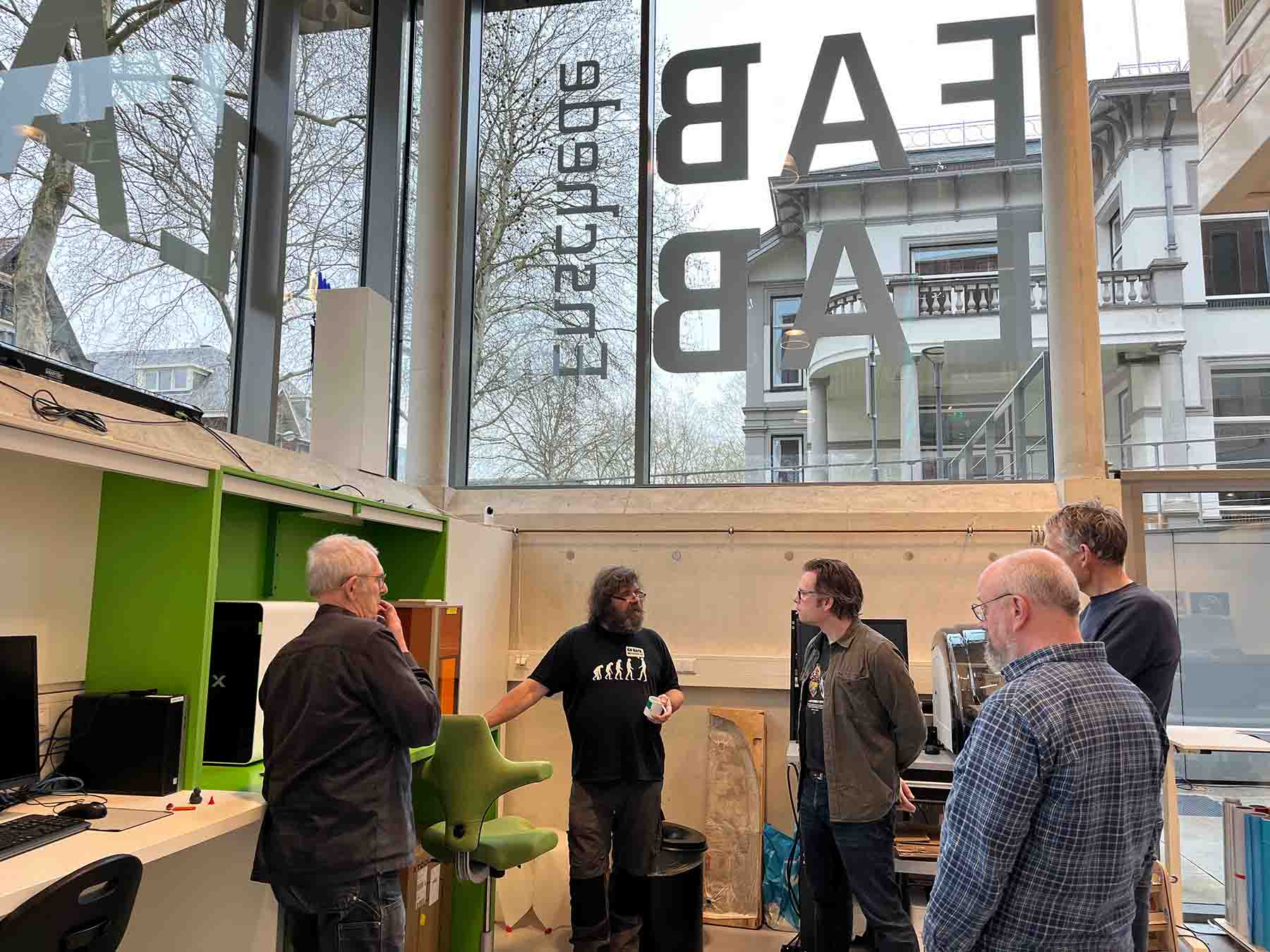
Group assignment
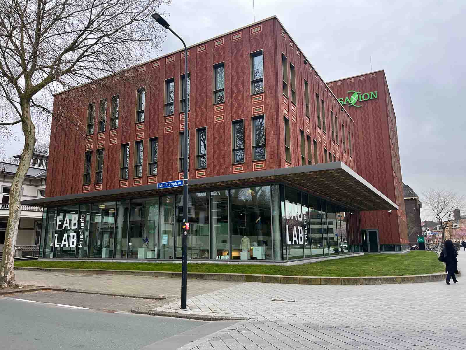
This week we went to Enschede to visit Leo, how works at the Fab Lab. He gave us a great tour and showed us how the students work with the lab. It was a very fun and inspiring day, especially since I've never really been a student myself. Thank you Leo!
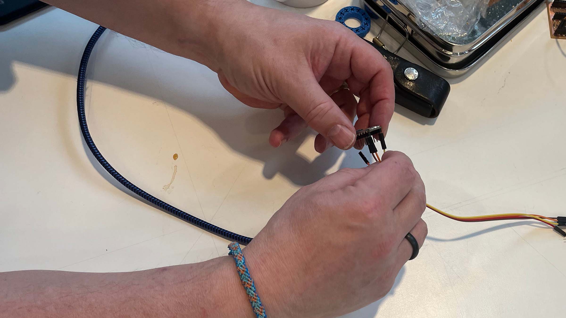
For our group assignment we set up serial communication between two XIAO RP2040 boards using UART, working with the custom boards we had produced in earlier weeks. We began simple, wiring the Xiao's together directly with jumper cables and connecting TX to RX according to Seeed’s pinout.
Once the physical connection was in place, we tested the link by sending messages between two computers. This quickly turned into a simple back-and-forth exchange to confirm everything was working.
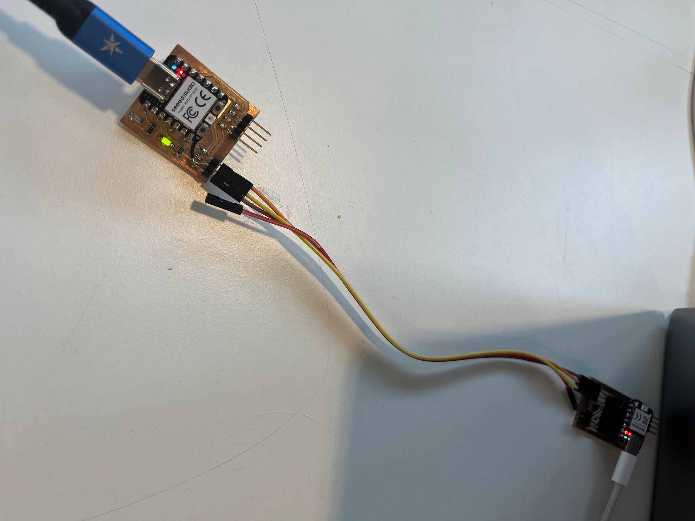
The more interesting challenge came when we tried to connect two existing projects rather than just two bare Xiao's. We initially assumed any available pins would work for UART, but that approach failed. The issue turned out to be more specific: UART on the RP2040 relies on dedicated hardware peripherals, and there are only two available. That means only certain pin combinations are valid, depending on how those peripherals are mapped.
After checking the documentation (notably section 4.2 on UART in the RP2040 datasheet and the MicroPython implementation), we identified which pins could actually function together. Luckily, the boards we had built still offered enough flexibility to find a working configuration, and we were able to establish a stable connection between the two projects.
For more information and code examples on our group assignment check out the documentation of my classmates Remco and Chris.
Files & resources
Leftovers previous week
- week 10 documentation