16 - System Integration
Summary
This week the assignment was to design and document the system integration for my final project, Still Here.
Approach
For this week I want to move from separate tests and prototypes toward one complete system plan. Instead of only listing parts, I need to explain how the physical curtain, electronics, sensors, code, power and interaction logic fit together.
The goal of this page is to document the integration decisions before building the final version, so I can spot missing pieces, risky assumptions and dependencies between subsystems early. Mostly this week has shown me how it's decision time and I should really focus on getting the details clear ASAP.
Assignment
- Design and document the system integration for your final project
Final project recap
Still Here is a curtain that nudges you to step away when you have been in the same space for too long. It is built around the experience of getting so absorbed in a project that taking a break gets pushed aside and self-care is neglected. Timers or notifications are often too easy to ignore, so this project turns the reminder into something physical: a doorway object you have to pass through.
 Britney Spears, Robert Sebree 2000
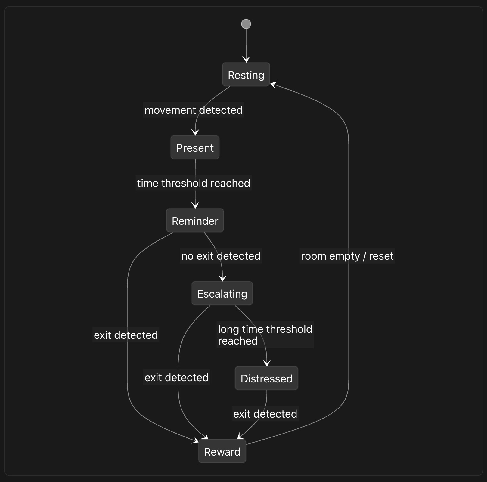
The curtain first is calm and easy to dismiss, but over time it becomes more insistent. It shifts from subtle color changes to increasingly intense light patterns until it becomes hard to stay put. It takes the form of a 90s doorway bead curtain, using a familiar decorative object as the base for an interactive system. Passing through the curtain becomes the action that resolves the reminder.
The main system parts are:
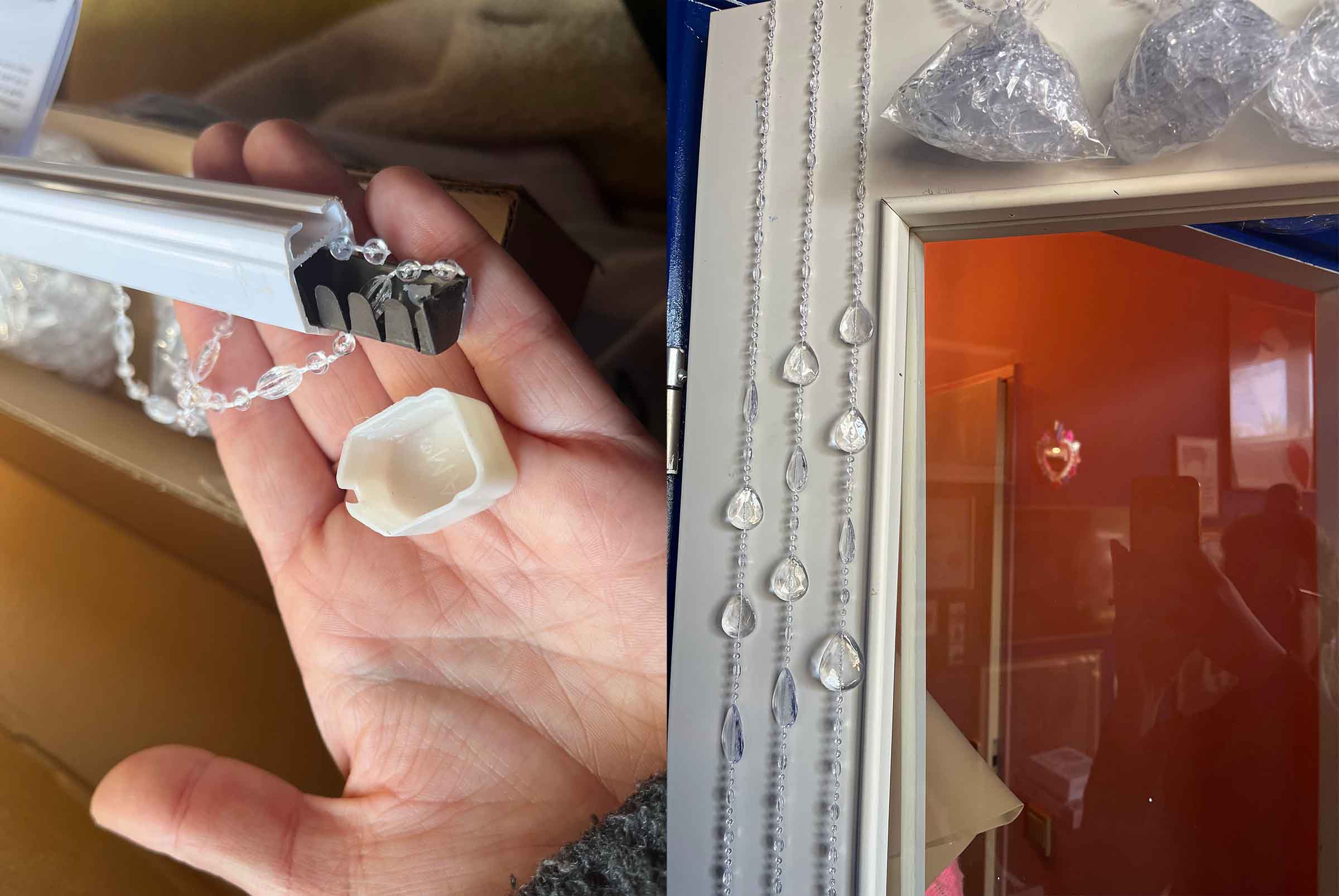
- Physical structure: a doorway curtain made from hanging strands and bead-like LED nodes
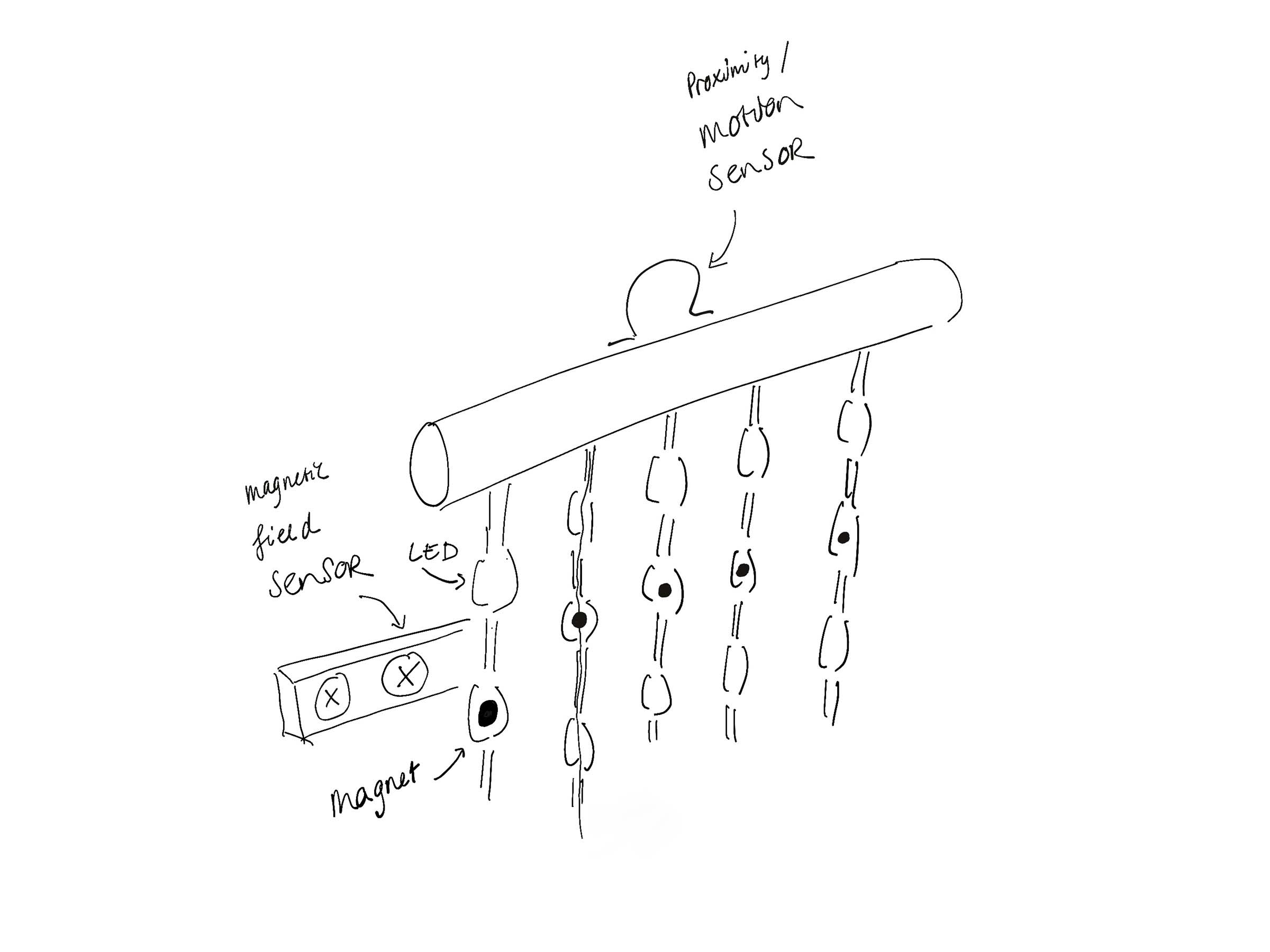
- Input: sensors that detect presence, passage through the curtain and/or movement of the strands
- Processing: a microcontroller that tracks state and translates sensor input into behavior
- Output: addressable RGB LED strands that show calm, warning, distressed and reward states
- Power: an external power supply for the LED strands and regulated power for the controller and sensors
- Software: embedded code for reading sensors, controlling LEDs and managing the interaction logic
System diagram
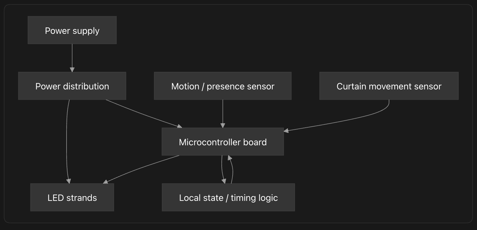 All diagrams on this page are made by Codex
Subsystems
Physical structure
- TODO: design top bar
- Planned doorway size: 90x200
- Number of strands: 10
- Beads or LED nodes per strand: 20
- Distance between LEDs: 10cm
- Mounting method: top bar will be either laser or 3d printed based on the actual 90s bead curtain top bar but with spaces for pcb mounting, sensors and cable management
- Cable routing: needs to be decided
- Mechanical strain relief: 3d printed teeth holding the strands in place
Electronics control
- TODO: decide whether a level shifter is needed
- Microcontroller: Raspberry Pi Pico
- Board version: Raspberry Pi Pico or Pico W, depending on availability
- Number of available LED data pins: 10 pins needed, one for each strand
- Sensor pins: 2 or 3 pins reserved for motion and curtain movement sensors
- Communication/programming interface: USB, programmed with MicroPython
- Important limitations: Pico GPIO is 3.3V while the LED strands run on 5V, so I should test whether the data signal is reliable and add a level shifter if needed.
Inputs
- TODO: decide motion sensor
- TODO: test magnetic field sensor
| Input question | Sensor / method | Location | Status |
|---|---|---|---|
| Is someone on which sides of the curtain? | motion | top bar | final decision time |
| Are the strands moving? | magnetic field | top bar | needs testing |
Outputs
- LED type: 5V WS2812-compatible addressable RGB LEDs
- Voltage: 5V
- Number of strands: 10
- LEDs per strand: 20
- Total LED count: 200
- Data line plan: one pin per strand
- Expected maximum current: 12A if all 200 LEDs are on full white at 60mA each
- Brightness limit in software: limit to 30-40 percent brightness for normal use
Power
- LED voltage: 5V
- Controller voltage: 5V
- Sensor voltage: 5V
- Maximum theoretical current: 200 LEDs x 60mA = 12A
- Planned brightness/current limit: 30-40 percent, so around 3.6A to 4.8A for the LEDs during normal use
- Selected power supply: 5V 15A minimum, 5V 20A preferred if available for extra margin
- Ground connection strategy: connect LED ground, Pico ground and sensor ground together
- Cable thickness / connector choice: use thicker wire for the main 5V and GND distribution, then split into lighter wires per strand
Power calculation:
| Part | Amount | Current per part | Maximum current |
|---|---|---|---|
| LEDs | 200 | 60mA | 12A |
| Raspberry Pi Pico | 1 | about 100mA | 0.1A |
| Sensors | 2 or 3 | estimate 50mA each | 0.15A |
| Total theoretical maximum | about 12.25A | ||
| With margin | 15A minimum |
For one strand this means:
20 LEDs x 60mA = 1.2A maximum per strand
In normal use the LEDs should be much lower than this, because the software will limit brightness and the curtain will not run all LEDs at full white. Still, designing for the maximum helps prevent overheating, voltage drop and random resets.
Software architecture
The software will be running on MicroPython, either using an existing libraries or writing my own for the sensors and LEDs. One motion sensor and the LEDs code has been tested.
- TODO: decide libraries and dependencies
Integration plan
Interfaces between subsystems
- TODO: decide on connectors
| From | To | Connection | Notes |
|---|---|---|---|
| Power supply | Power distribution | TODO | TODO |
| Power distribution | LED strands | TODO | TODO |
| Power distribution | Microcontroller | TODO | TODO |
| Microcontroller | LED strand x | TODO | TODO |
| Sensor 1 | Microcontroller | TODO | TODO |
| Sensor 2 | Microcontroller | TODO | TODO |
Physical integration
-
TODO: design top bar
-
Where the control board will live: TODO:
- How it will be mounted: TODO:
- How wires are hidden or organized: TODO:
- How the curtain remains flexible: TODO:
- How the system can be opened for repair: TODO:
- How the USB/programming connection remains accessible: TODO:
Risk list
| Risk | Why it matters | Mitigation / test |
|---|---|---|
| LEDs draw too much current | Could overheat wires or crash the system | Use a 5V 15A minimum power supply, add a fuse and limit brightness in software |
| Voltage drop over long strands | LEDs may flicker or change color | Feed power through a thicker distribution line and test voltage at the end of the strands |
| Pico data signal is too low for the LEDs | The Pico outputs 3.3V logic while the LEDs run on 5V, which may make the LED data unreliable | Test one full strand from the Pico before final assembly and add a level shifter if the signal is unstable |
| Sensor readings are noisy | The curtain may trigger at the wrong moment or miss someone passing through | Log raw sensor values first, test both sides of the curtain and add thresholds, timing filters or averaging in software |
| Motion sensor cannot tell direction | The project needs to know whether someone is leaving or returning, not only that movement happened | Use two sensors or combine motion sensing with curtain movement sensing, then test real walk-through scenarios |
| Magnetic field sensor does not clearly detect strand movement | The sensor may not be sensitive enough or may need a very specific magnet position | Test magnet placement on one strand before designing the full top bar |
| Wires break from movement | Curtain strands will be touched, pulled and moved often | Add strain relief at the top bar, avoid solder joints in moving sections and test by repeatedly moving one prototype strand |
| Connectors become confusing during assembly | Ten similar LED strands and multiple sensors can easily be plugged into the wrong place | Label connectors, keep strand order consistent and document the pinout before final assembly |
| Code becomes hard to debug once assembled | Integrated systems hide errors, especially when power, sensors and LEDs fail at the same time | Test each subsystem separately first, keep serial debug output and add simple test modes for LEDs and sensors |
| Physical design blocks maintenance | Repairs become too difficult if the electronics are sealed inside the top bar | Make the control board and power connections accessible, and design the top bar so it can be opened without destroying it |
Testing plan
Bench tests
- Test one LED strand
- Test all LED channels
- Test each sensor separately
- Test power supply under load
- Test shared ground and signal stability
Integration tests
- Run LEDs and sensors at the same time
- Test state transitions with simulated input
- Test state transitions with the physical curtain
- Test long-running behavior
- Test recovery after reset or power loss
User / interaction tests
- Does the curtain notice someone nearby?
- Does it correctly detect someone passing through?
- Does the escalation feel understandable?
- Does the reward state feel clear?
- Is any part annoying, unsafe or too fragile?
Decisions to make
- Final sensor combination
- Connector system
- Mounting and enclosure design
- Brightness limits
- Final interaction timing
Leftovers previous weeks
- week 11 individual assignment
- week 14 documentation
- nueval feedback henk
- nueval feedback take