Electronics Design
Week 6 Assignment
Assignment Overview
Week 6: Electronics Design. Personal work is documented first, then group work.
👤 Personal Work
My First PCB Board — designed using Fusion 360.
🖥️ Design Preparation
Operating System: Mac
Design Software: Fusion 360
Download: https://www.autodesk.com/products/fusion-360/overview
📐 Section 1: Planar Draft Design
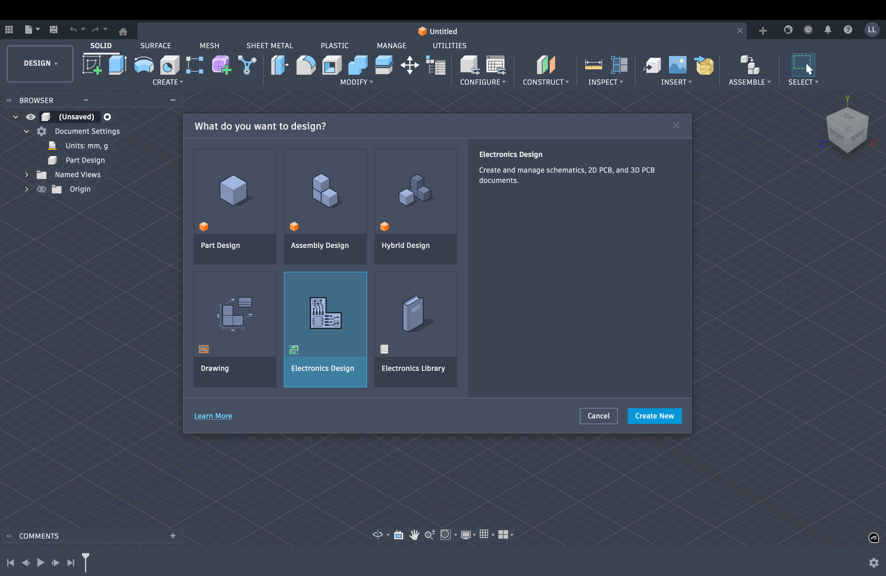
Create a New Electronics Design
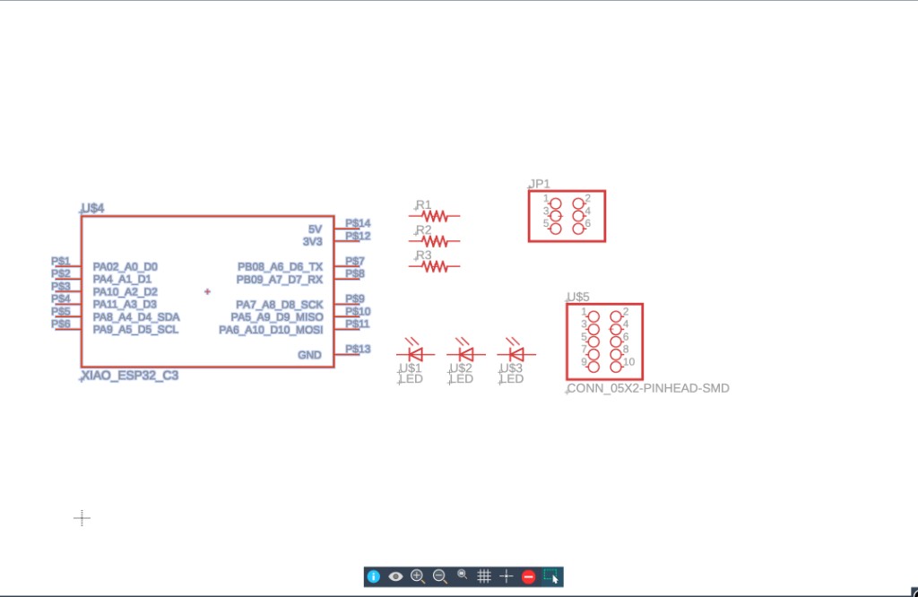
Open Fusion 360 and select Create new Electronics design to start a new PCB project.
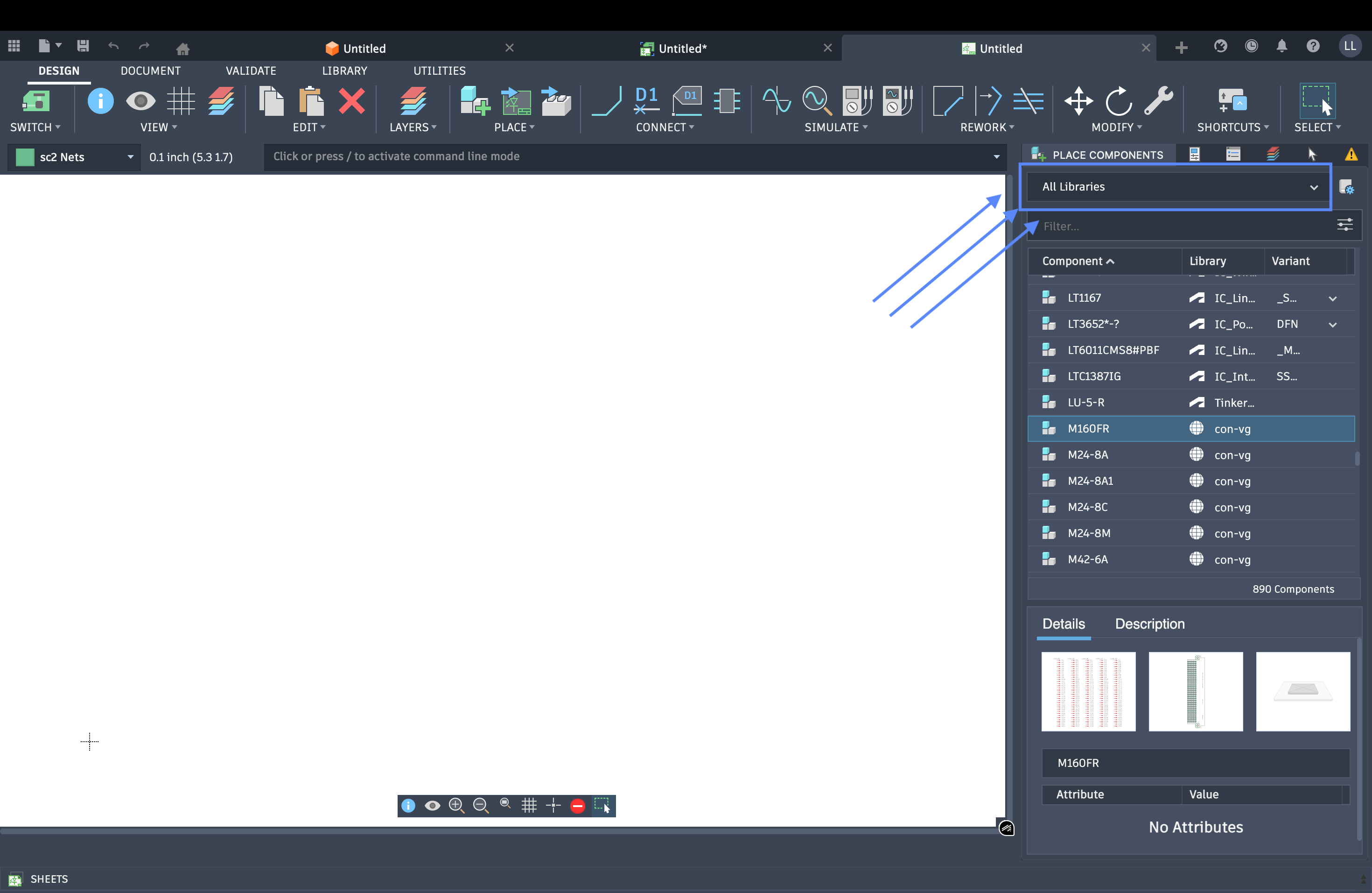
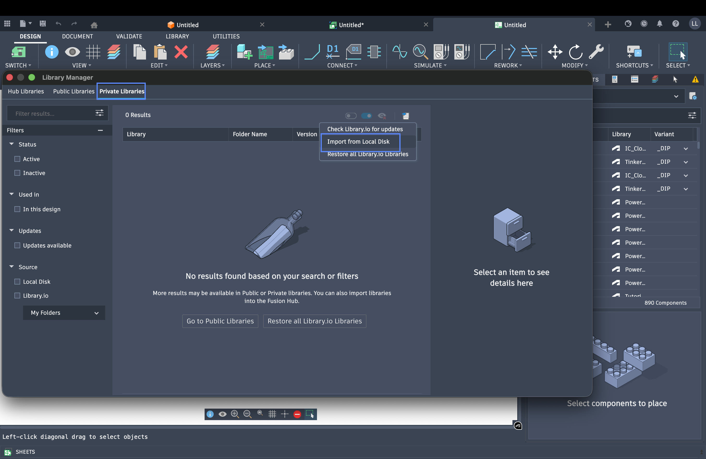
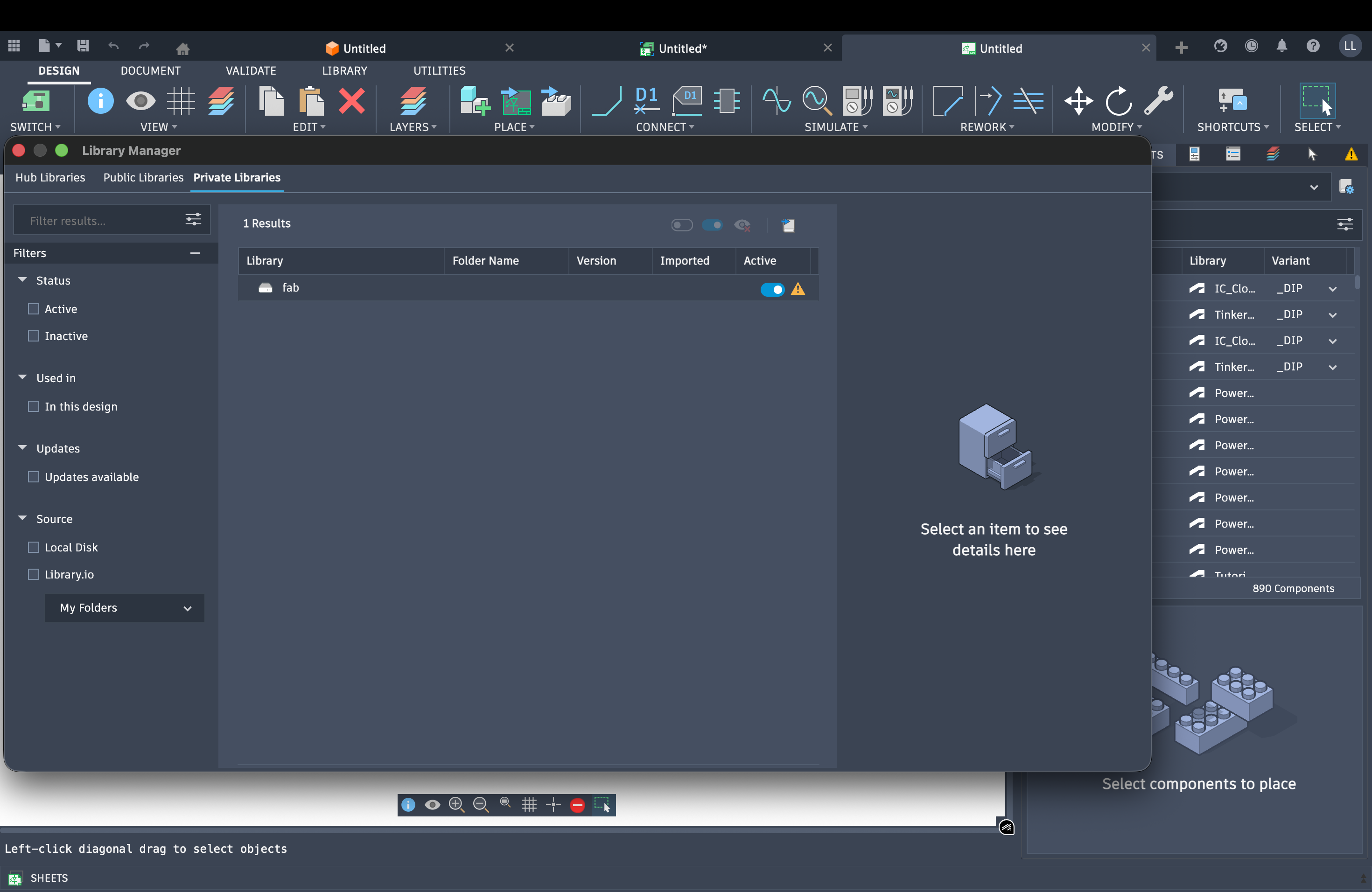
Add Components
Import and place the required components on the schematic. The images below show the process of adding components to the design. Click any image to view full size.
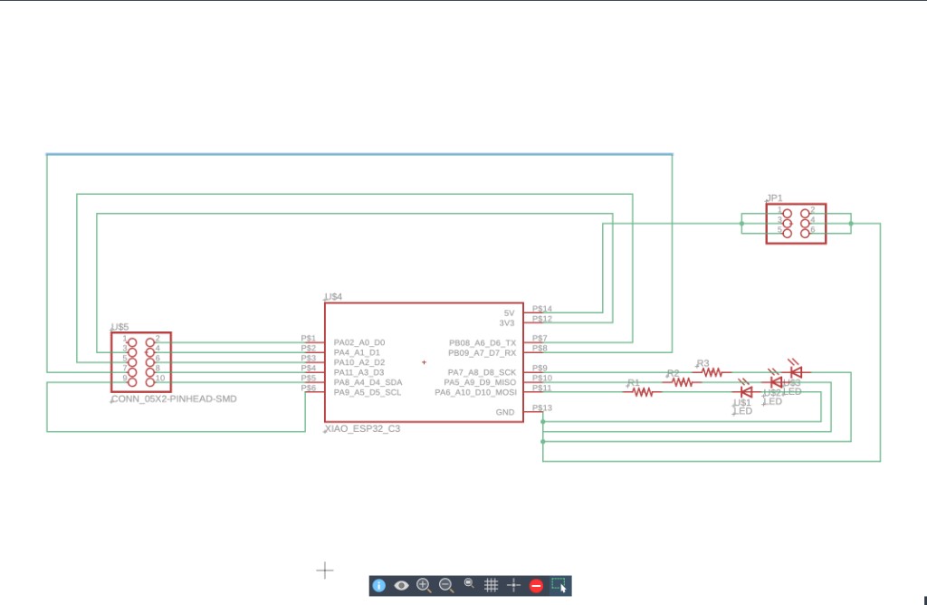
Add and Connect Wires
After placing the components, add wires and connect the circuit traces between them to complete the schematic.
🔌 Section 2: Adjust Routing & Draw the Board
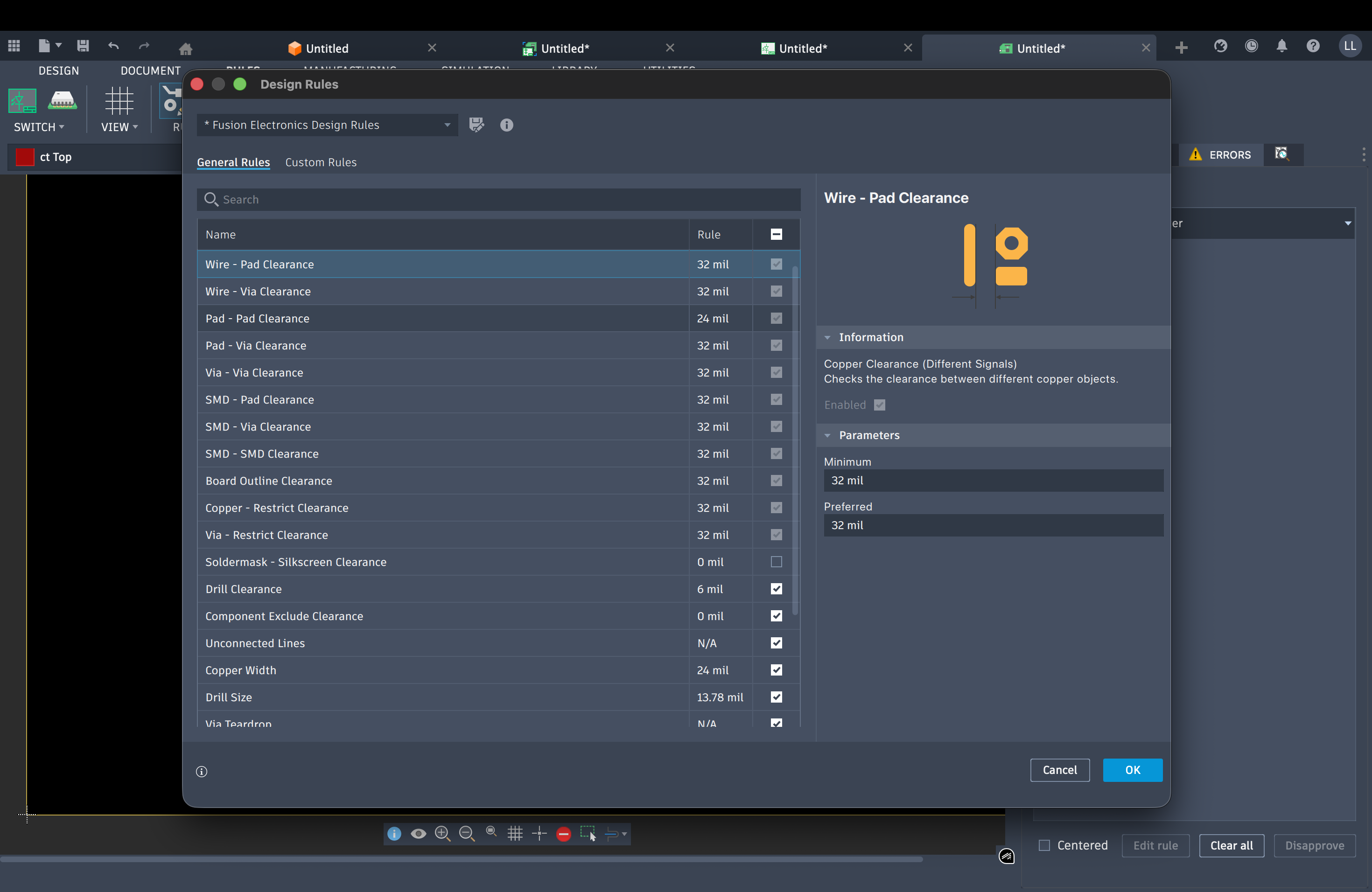
After completing the schematic draft, click Switch to enter 2D circuit editing mode. Then click Rules, select Design Rules to configure your routing rules.
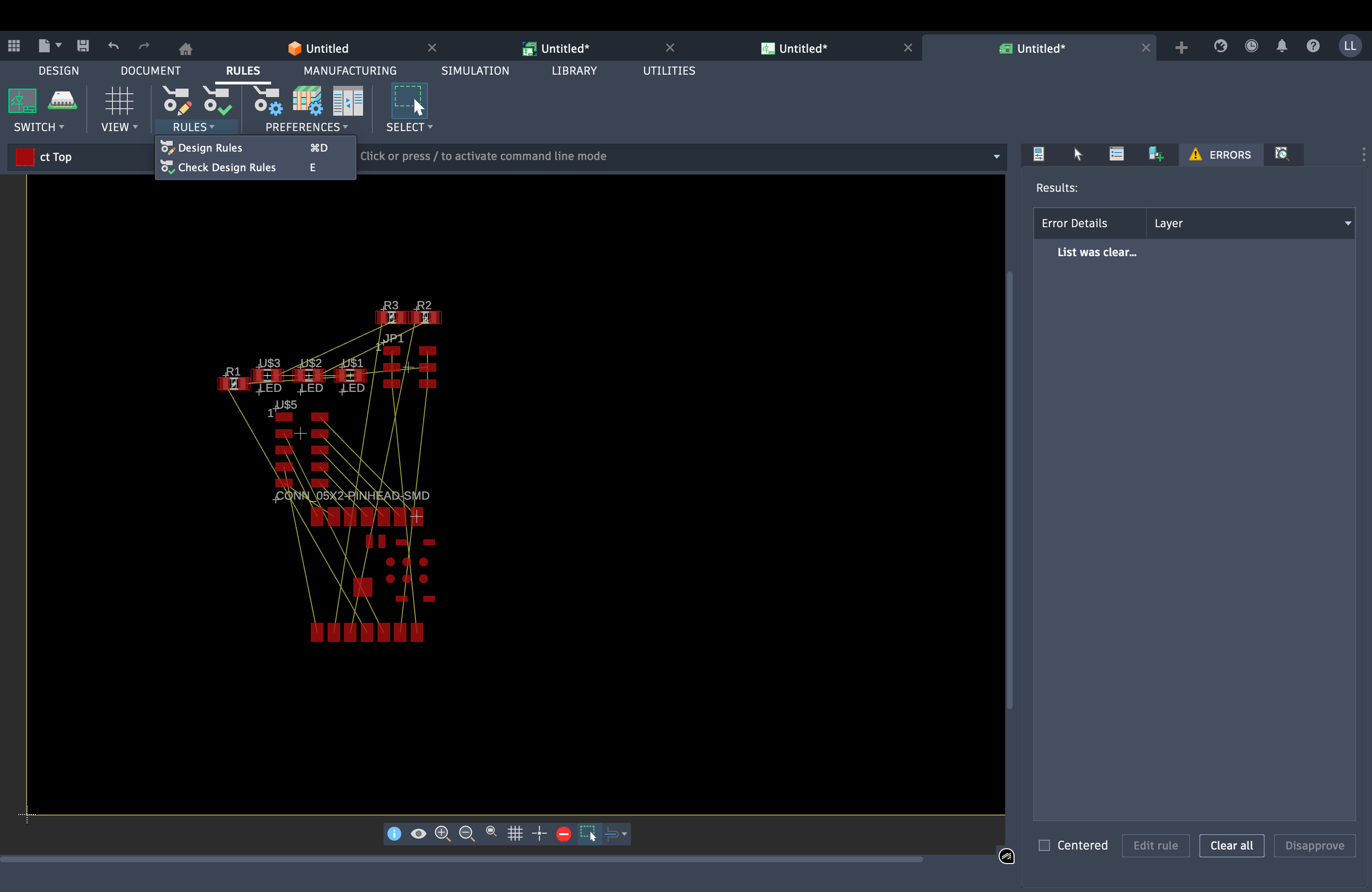
Arrange the traces, then click Quick Route → Automatic Route for automatic routing. Next, click Route → Check Design Route to verify there are no unconnected traces.
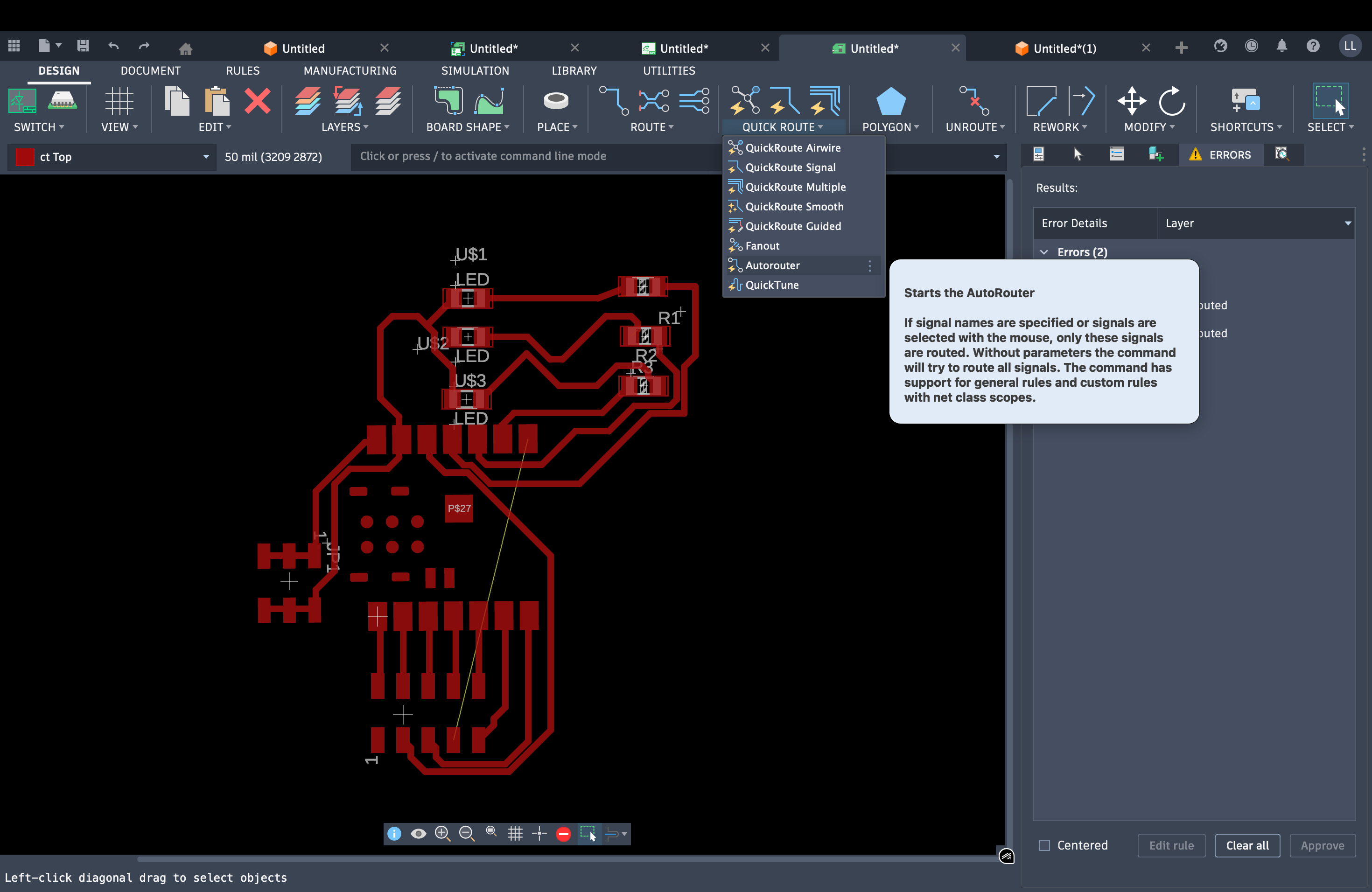
As shown in the image above, there may be some unconnected traces. Return to the schematic draft page and re-adjust the connections until there are no unconnected traces in the single-layer board. Finally, use BoardShape to draw the PCB board outline.
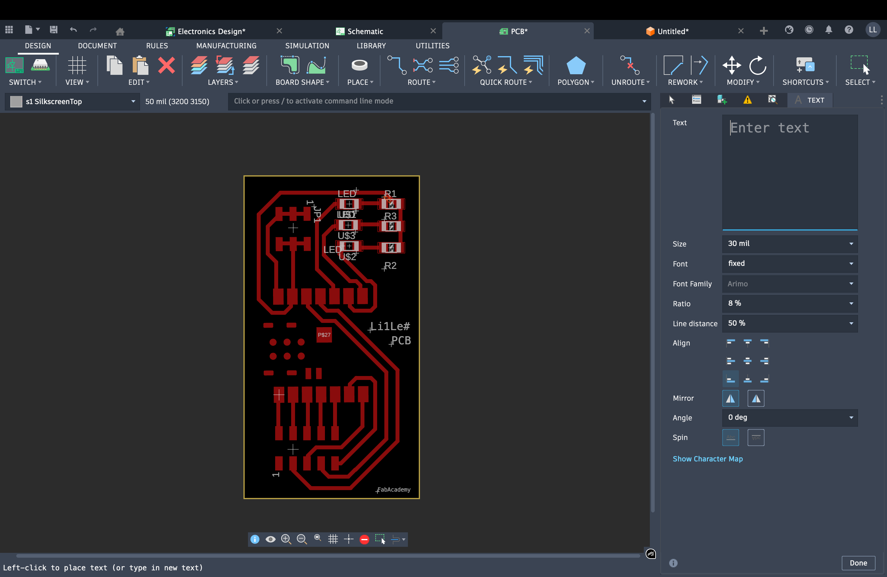
Finally press T to add a text box and place it on the PCB board. 😎
🔧 Section 3: Use CNC to Machine the PCB Board
Milling and production are documented in Week 8: Electronics Production.
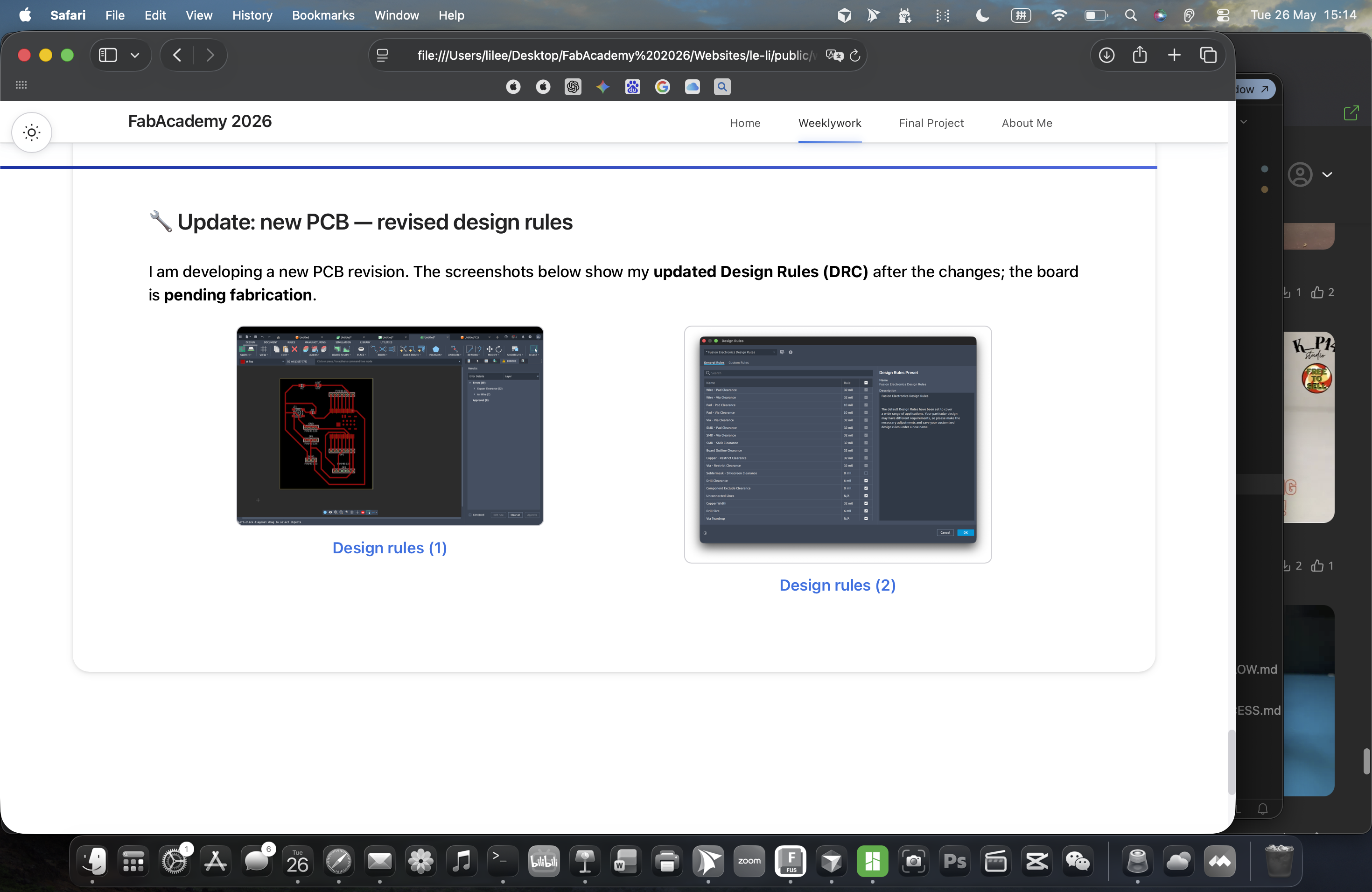
✅ Section 4: Final PCB Design (Revision V3)
After the first milled prototype failed (see Week 8), the electronics design was revised: connector pins in the sketch were changed to pin header footprints for reliable soldering and assembly. Below is the final design used for the updated board.
👥 Group Work
Group assignment content to be added.