Computer-Controlled Cutting
Week 3 Assignment
Assignment Overview
Week 3: Computer-Controlled Cutting. Individual work is documented first, then group work — matching how this page is organized below.
Assignments
Group Assignment
- Do your lab’s safety training
- Characterize your laser cutter’s focus, power, speed, rate, kerf, joint clearance and types
Individual Assignment
- Cut something on the vinyl cutter
- Design, laser-cut, and document a parametric construction kit, accounting for the laser-cutter kerf
Extra credit: design it to be assembled in multiple ways · include elements that aren’t flat · engrave as well as cut
👤 Individual Work
Parametric modelling, laser-cut construction kit, and vinyl logo — documented from UNNC FabLab.
🖥️ Lab & software
Fab lab: UNNC FabLab (laser cutter, vinyl cutter)
CAD / parametric design: Autodesk Fusion 360
📐 Parametric Modelling
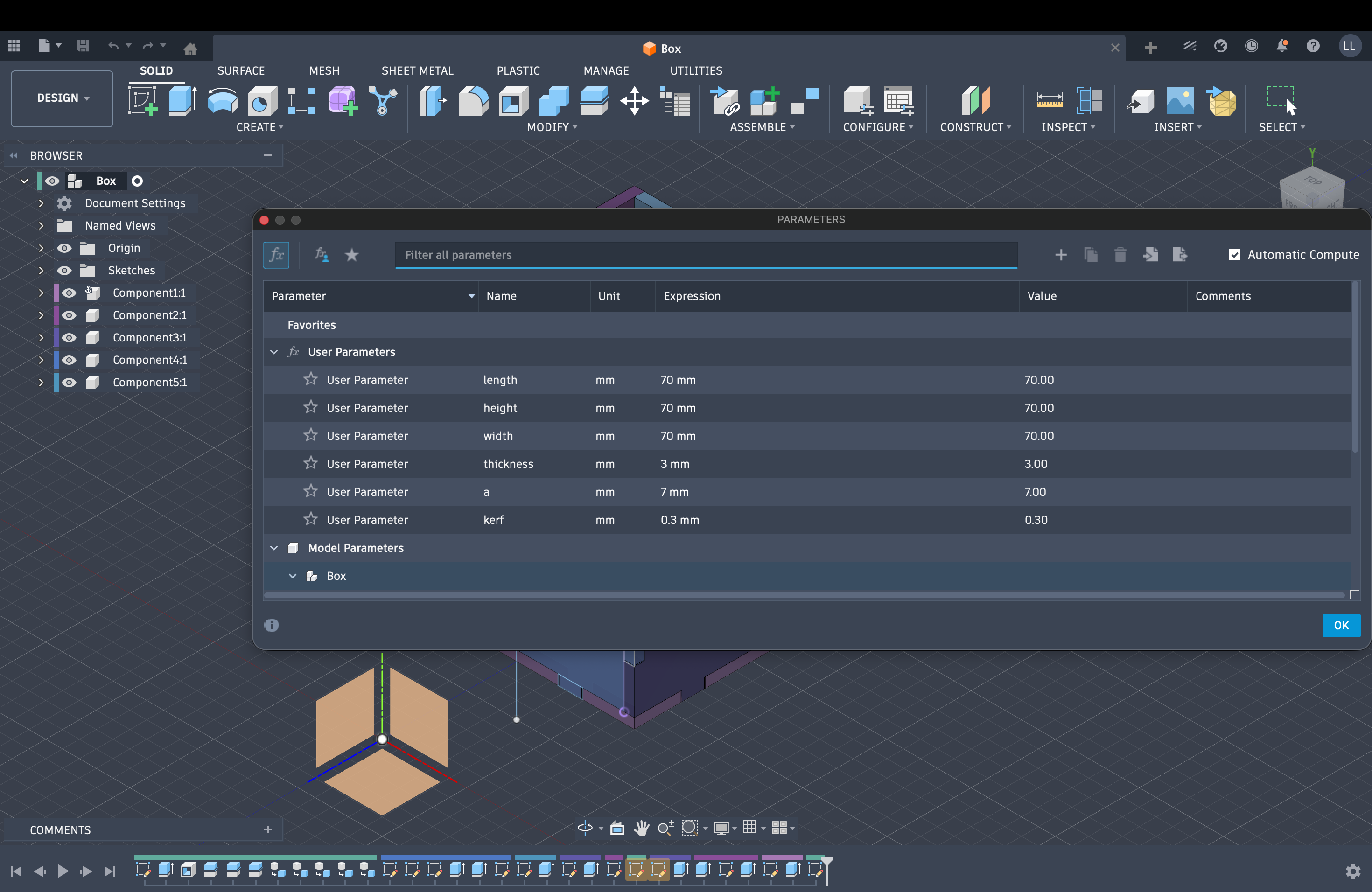
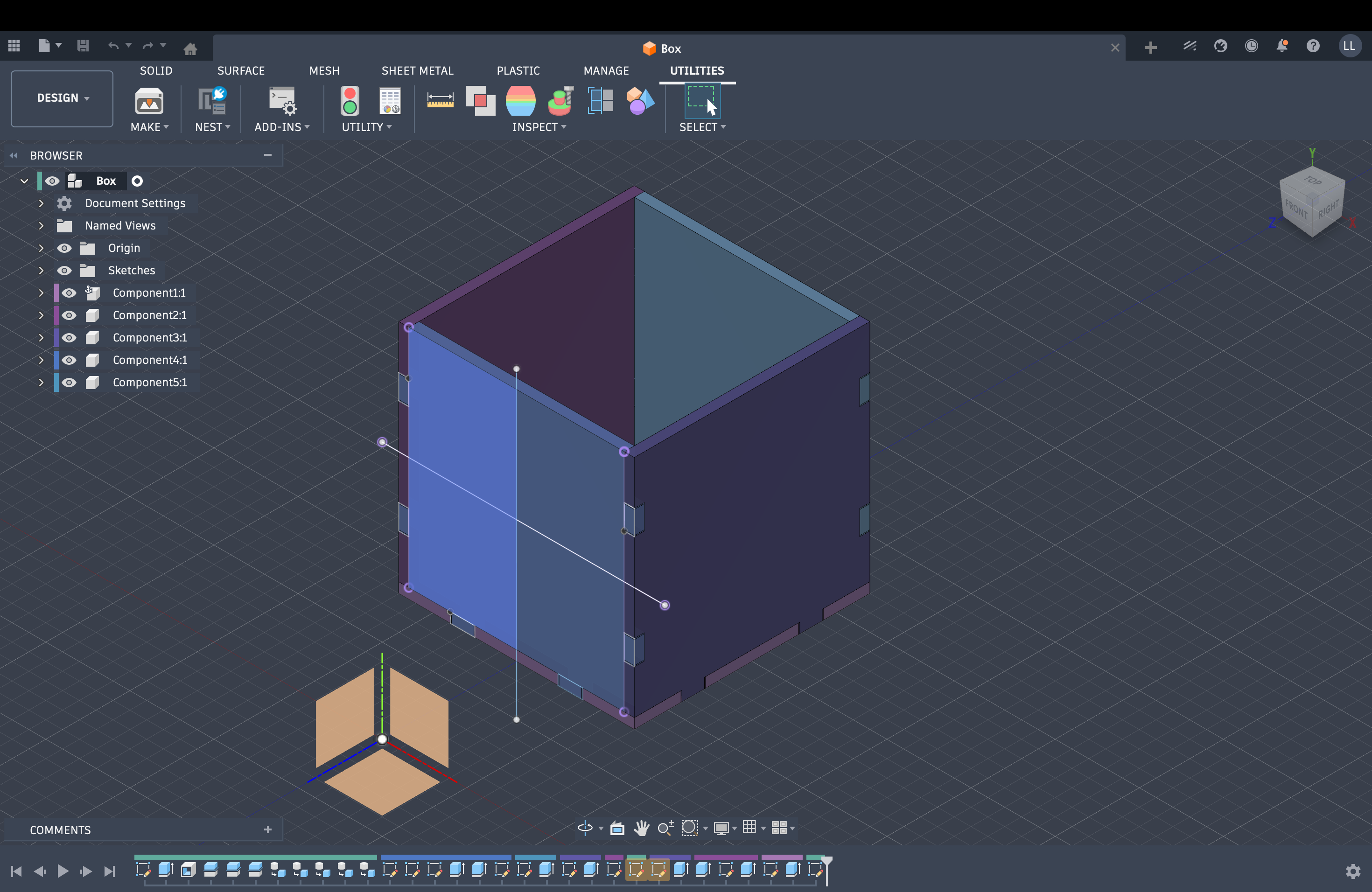
Fusion 360 — parametric workflow
I used Autodesk Fusion 360 for parametric modeling of the construction kit (sketches, constraints, and export for laser cutting). Screenshots of the CAD model:
✂️ Design and laser-cut a parametric construction kit
Modular construction kit
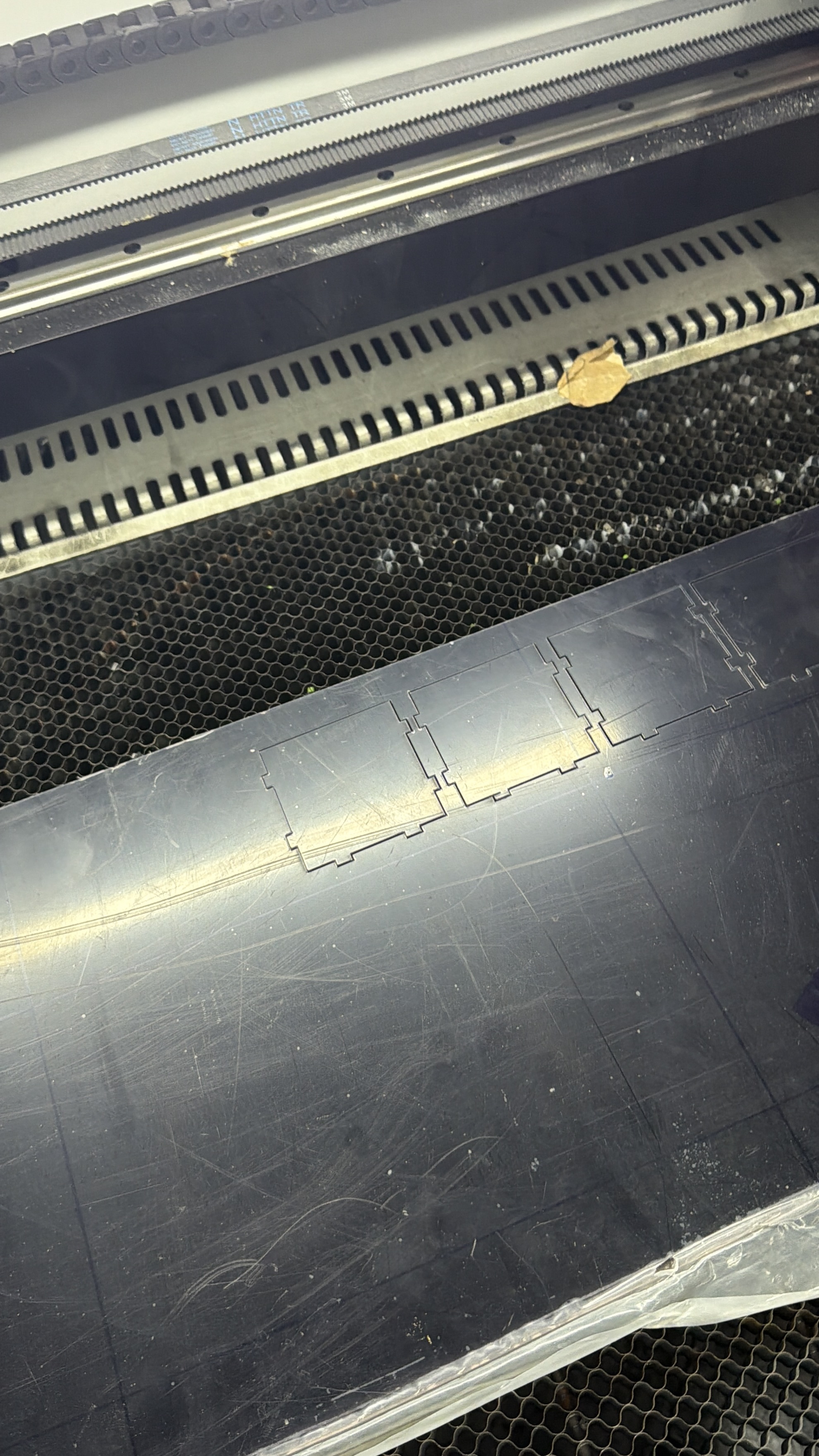
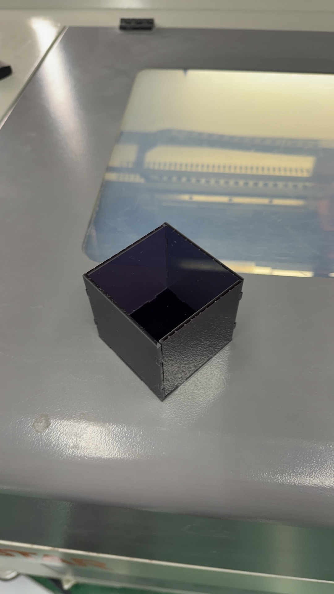
After finishing the model in Fusion, I cut the kit on the laser cutter at UNNC FabLab, accounting for kerf in the design. Below: video of the cut, then photos of the parts.
🏷️ Vinyl cutter
Logo cut at UNNC FabLab
Describe the process to cut my logo with the vinyl cutter at UNNC FabLab.
👥 Group Work
Laser safety and machine characterization — shared group documentation.
1. Cutting preset & speed vs energy
Below is our group video for this week: it shows the laser cutting preset we used (cut settings as documented for the group assignment).
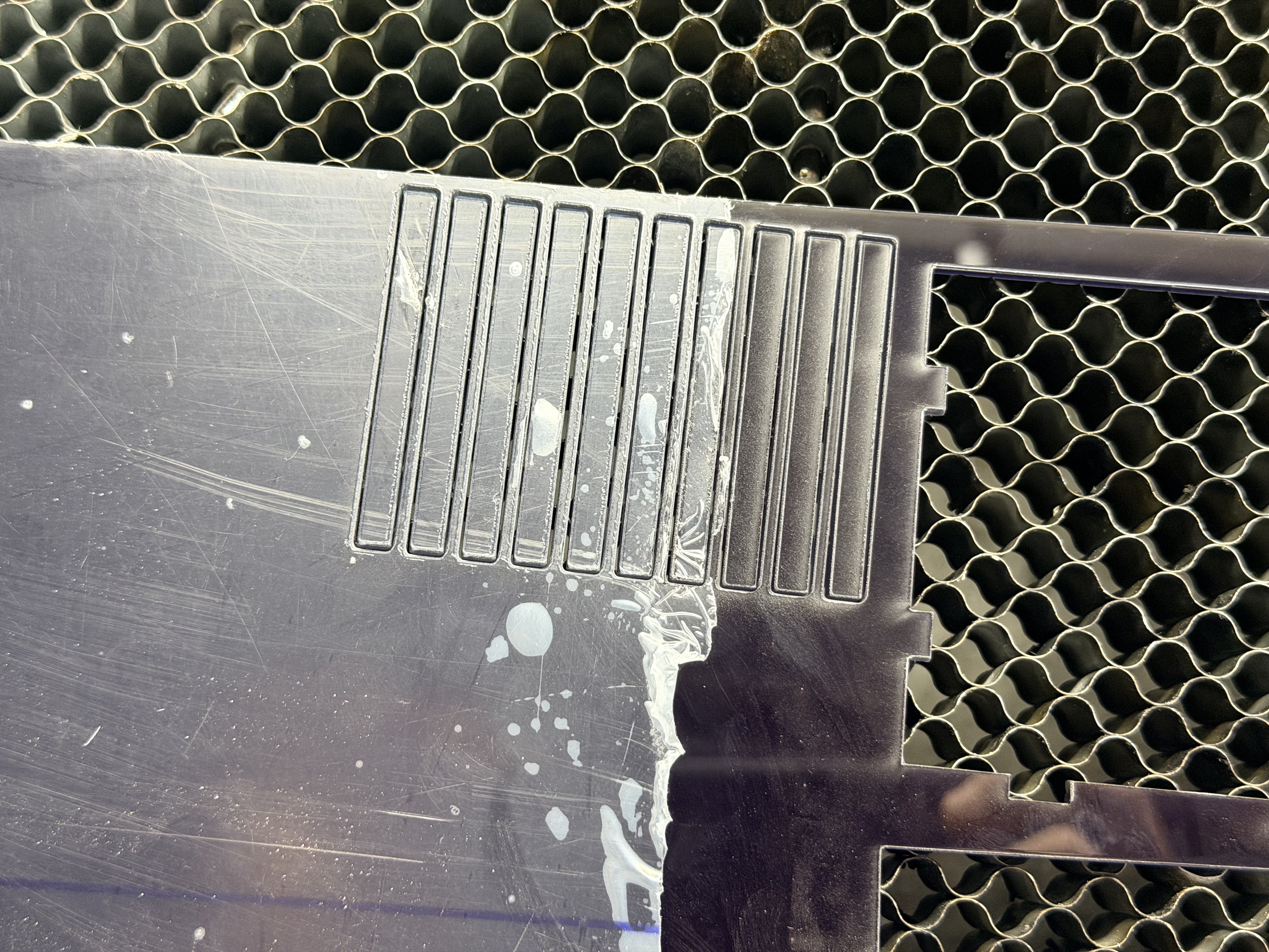
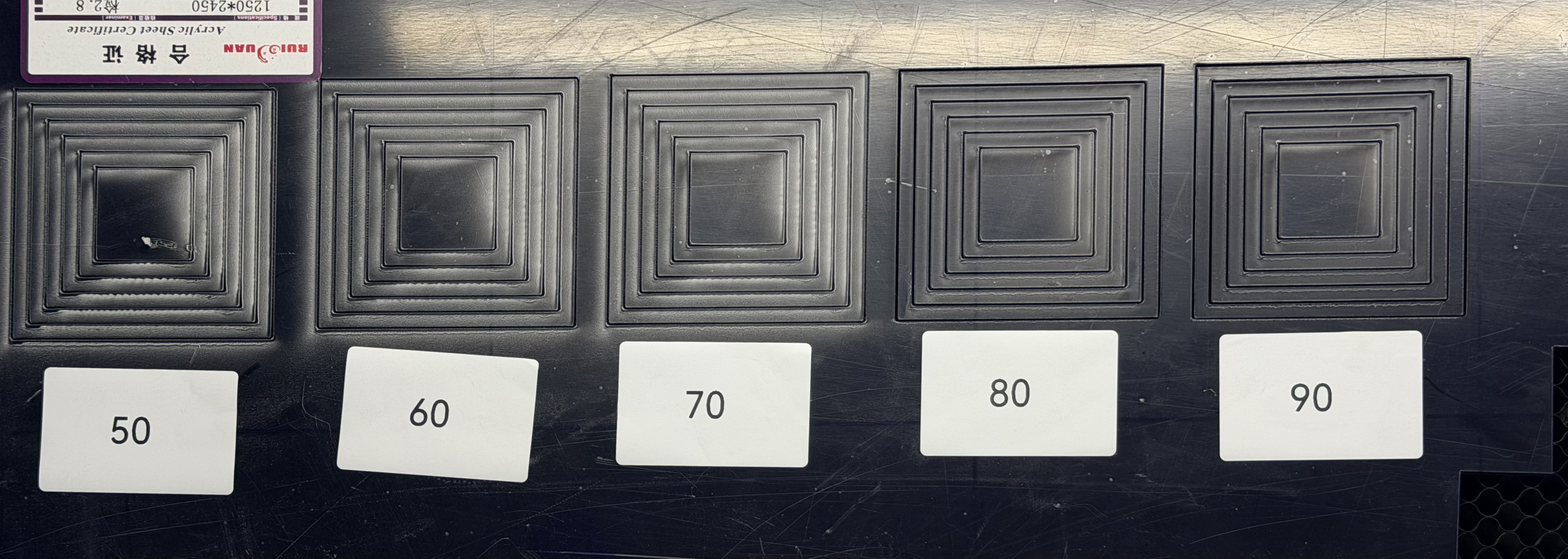
Group result: the photo below documents one of our characterization outputs; we used it to relate cutting speed to laser energy (how power and feed rate combine in practice).
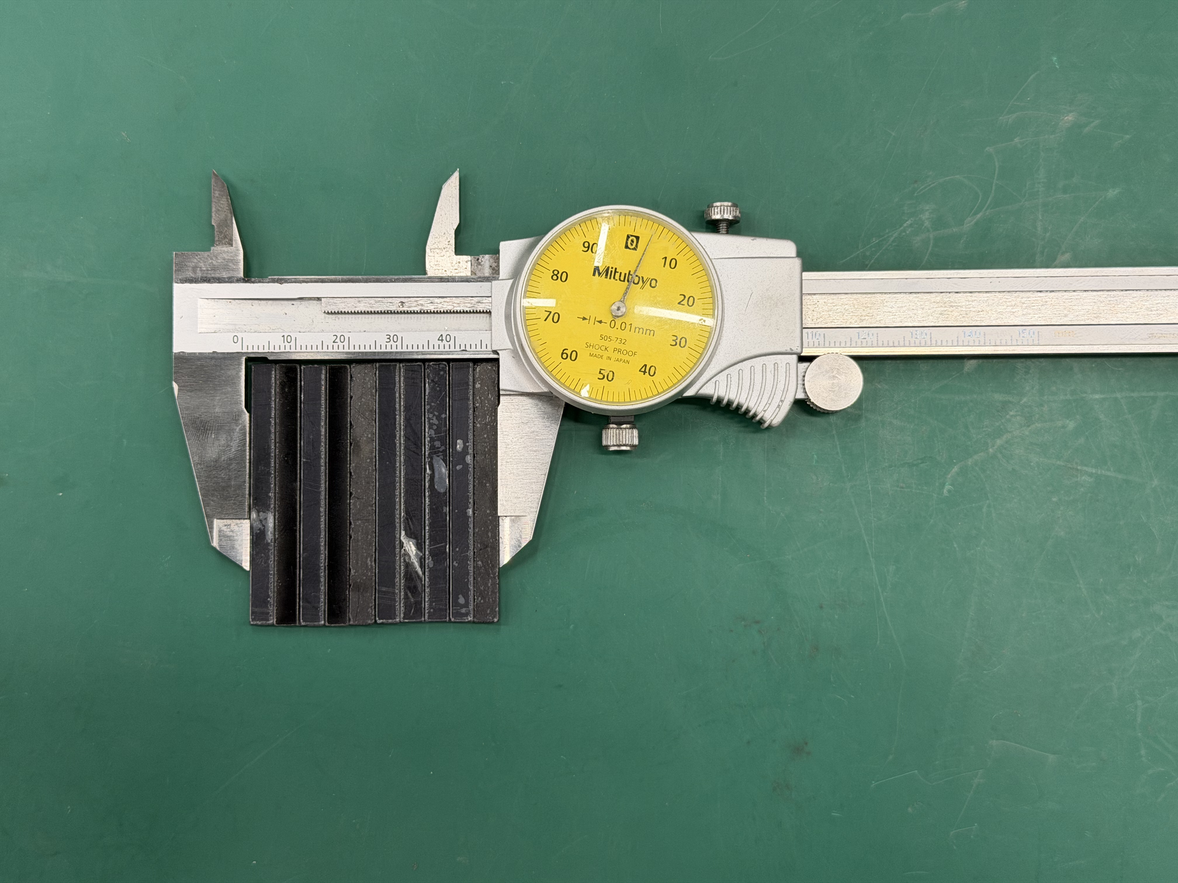
2. Kerf measurement
As the second group task we measured the laser kerf (the width of material removed by the beam). From the measurements below we estimate our kerf at approximately 0.3 mm.