Computer-Aided Design
CAD Design & Parametric Modeling
📌 Assignment Overview
This week focused on two main tasks: designing a 6-axis robotic arm prototype (Final Project Draft) and revisiting the modular box from Week 3. Used Fusion 360 with parametric modeling to make design changes easier.
📋 Assignment Process
This section documents the step-by-step process of completing this week's assignment.
1. Technical Workflow & AI Assistance
Environment Setup
- Operating System: macOS
- CAD Software: Fusion 360
- AI Tool: Gemini (for troubleshooting)
AI-Assisted Problem Solving
Used Gemini to solve these issues:
- Constraint Issues: Sketch constraints didn't update when parameters changed. Fixed by using "Update" command.
- Joint Alignment: Revolute Joints were misaligned. Used construction geometry and "Align" tool to fix.
- Parameter Organization: Grouped related parameters and used clear names for easier management.
2. Parametric Robotic Arm Design
Built the 6-axis arm in Fusion 360 as a sequential workflow — set up the design, create components one by one, then sketch, extrude, and add joints.
📐 Modeling Process
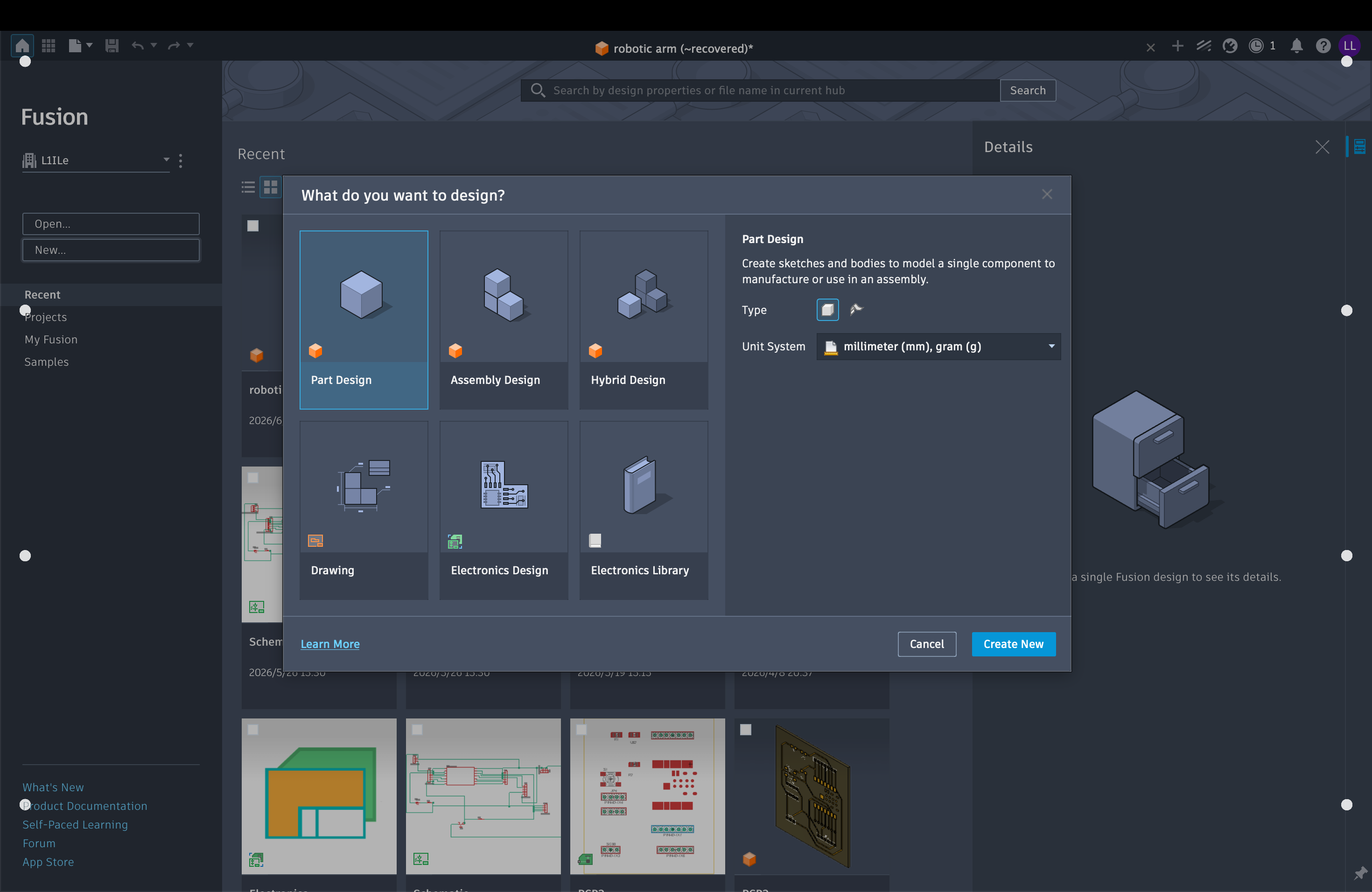
Create a Hybrid Design
In Fusion 360, start a new Hybrid Design — this supports both solid modeling and assembly components in one file.
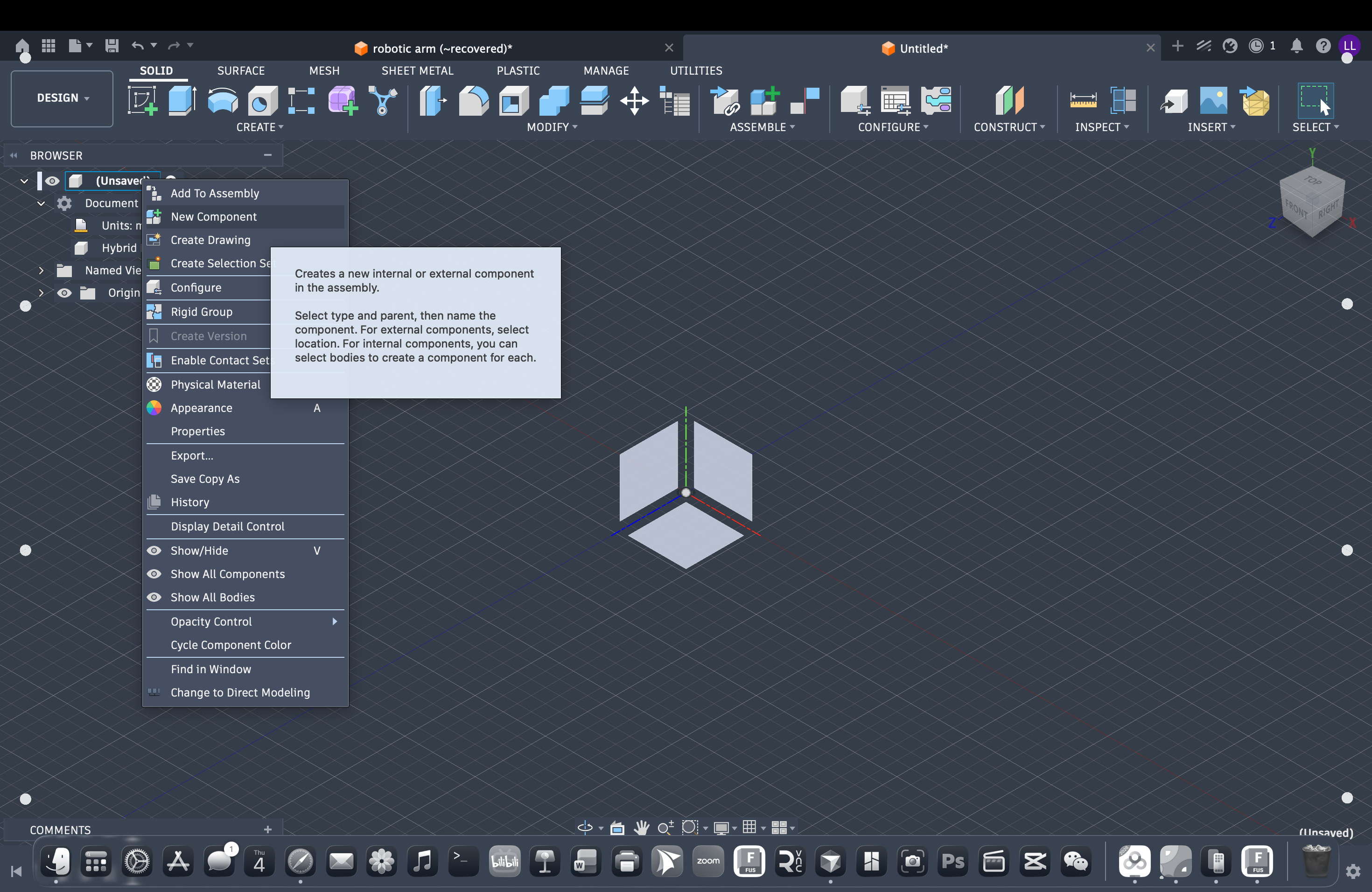
Create a new component
After the design opens, create a separate Component in the browser — each link of the arm lives in its own component.
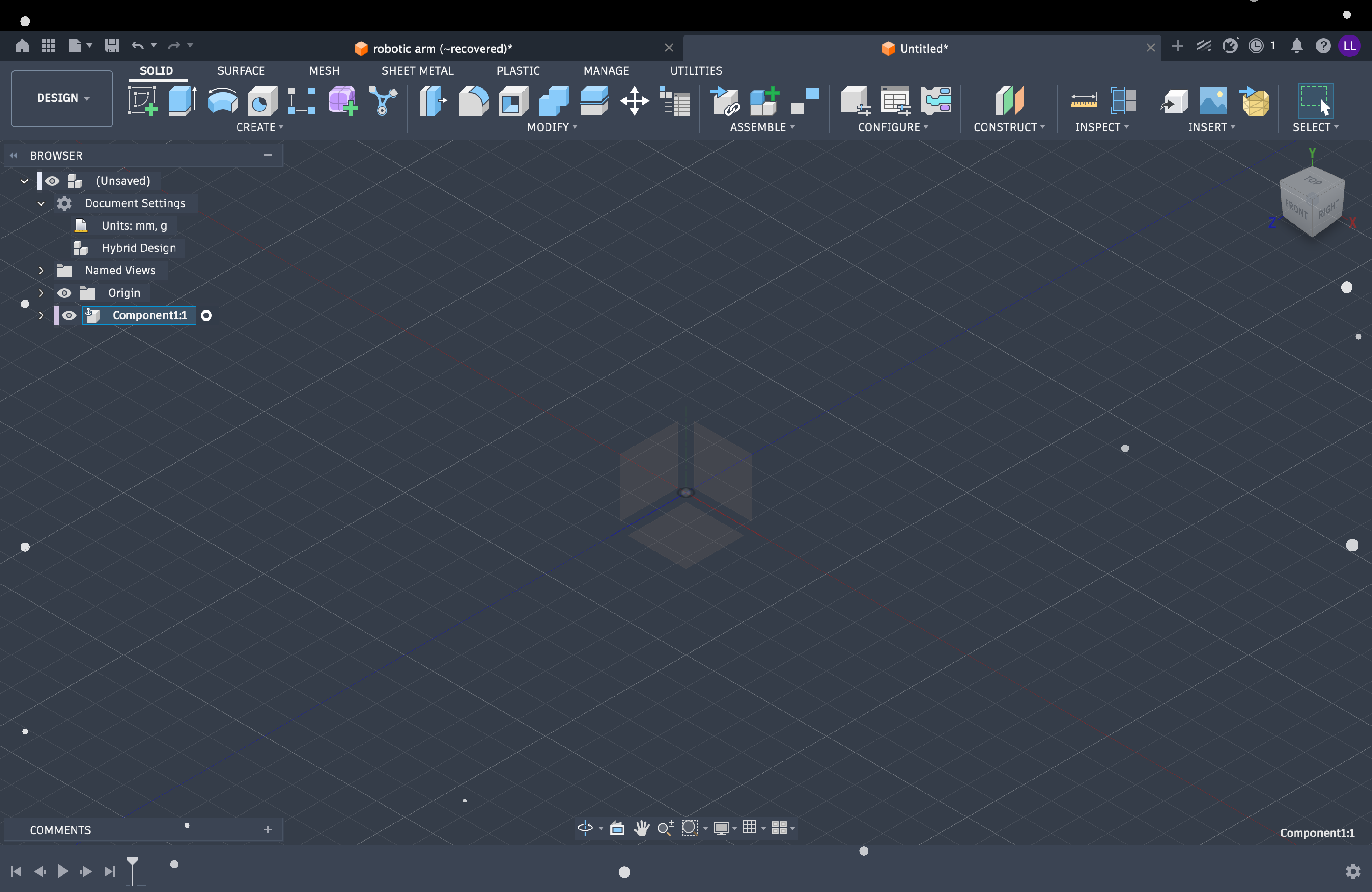
Activate the component
Select (double-click) the new component so it becomes active — all sketches and features are added inside this component.
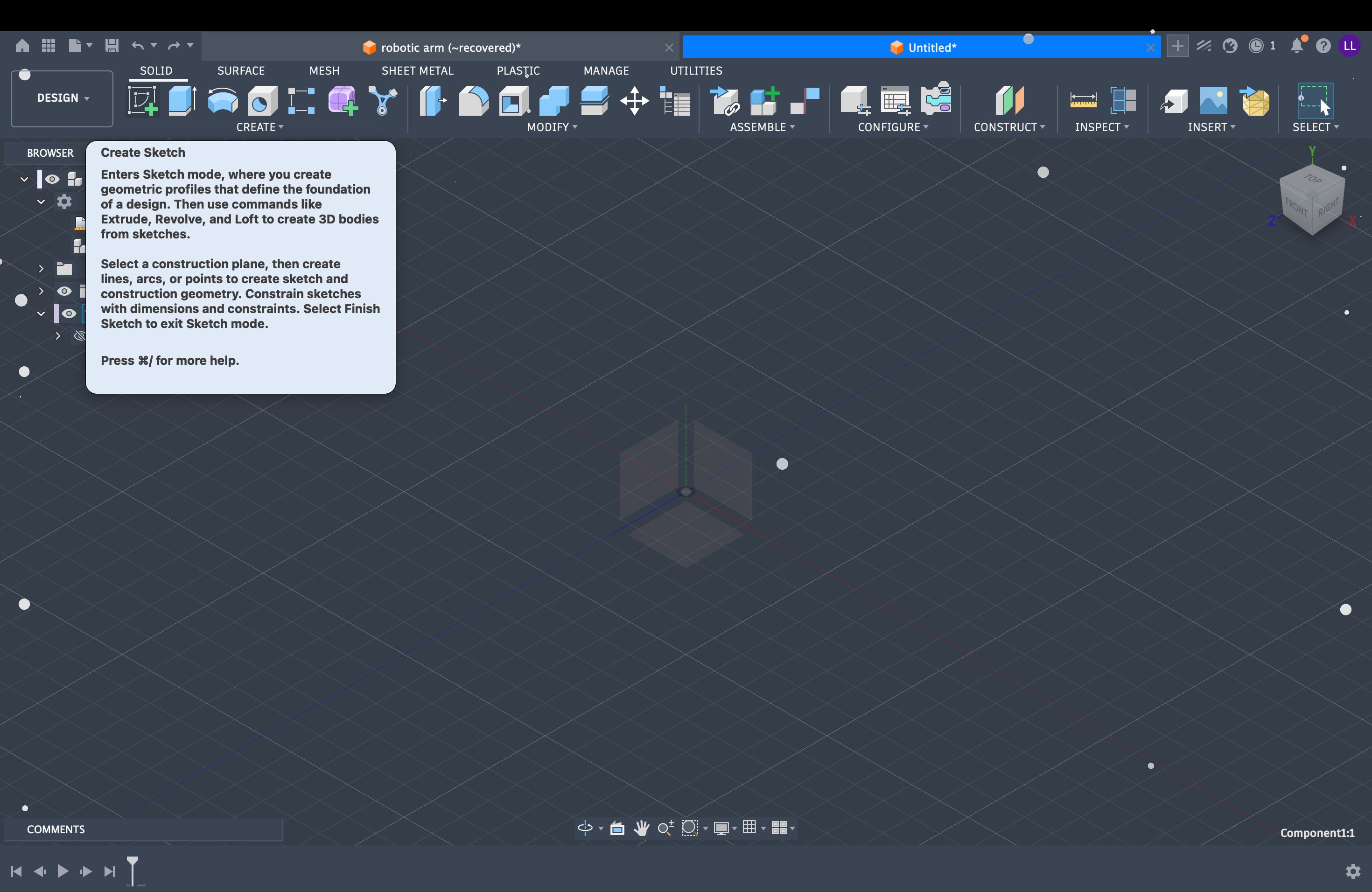
Create Sketch
With the component active, click Create Sketch and choose a plane to start drawing the profile.
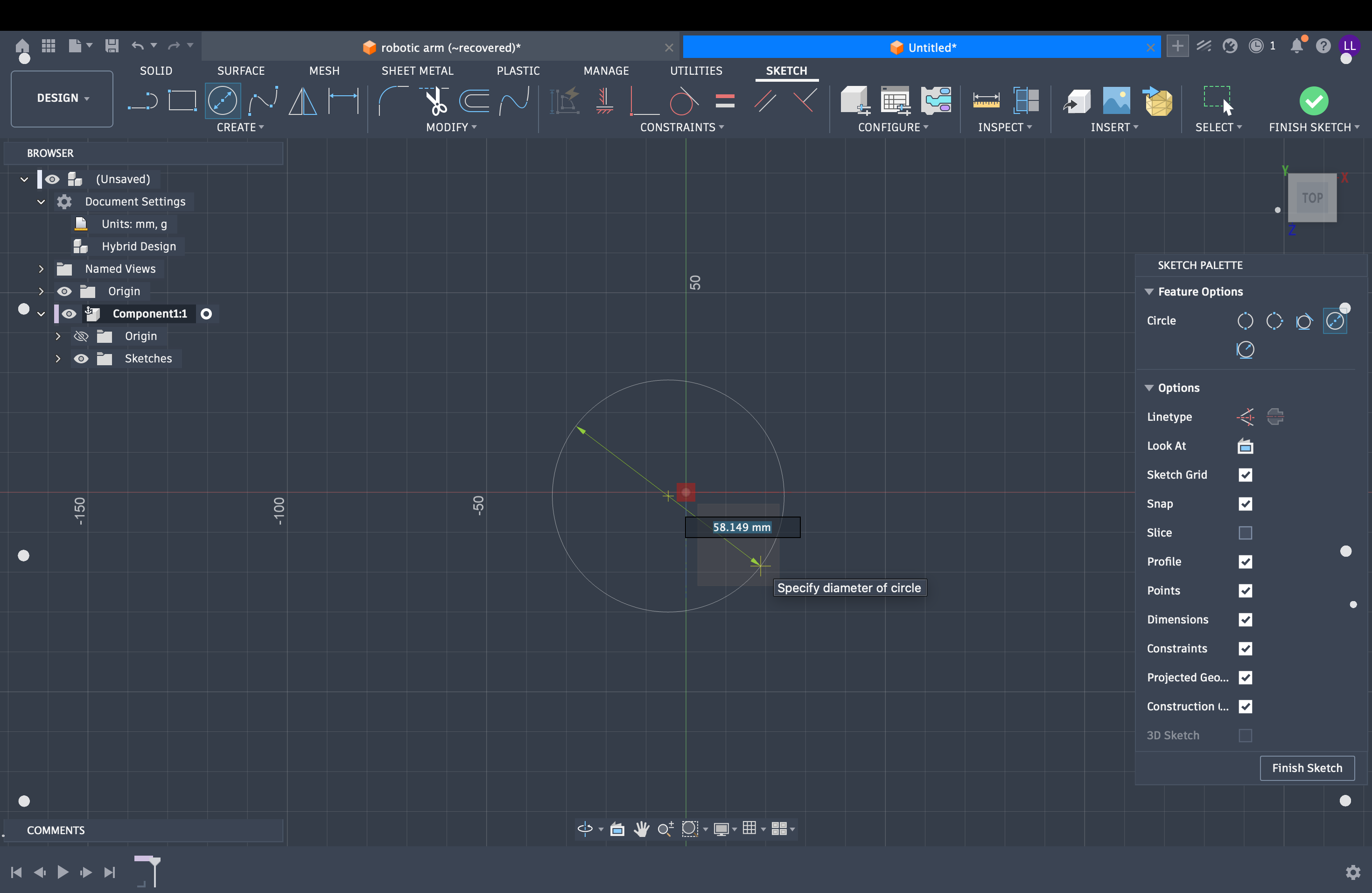
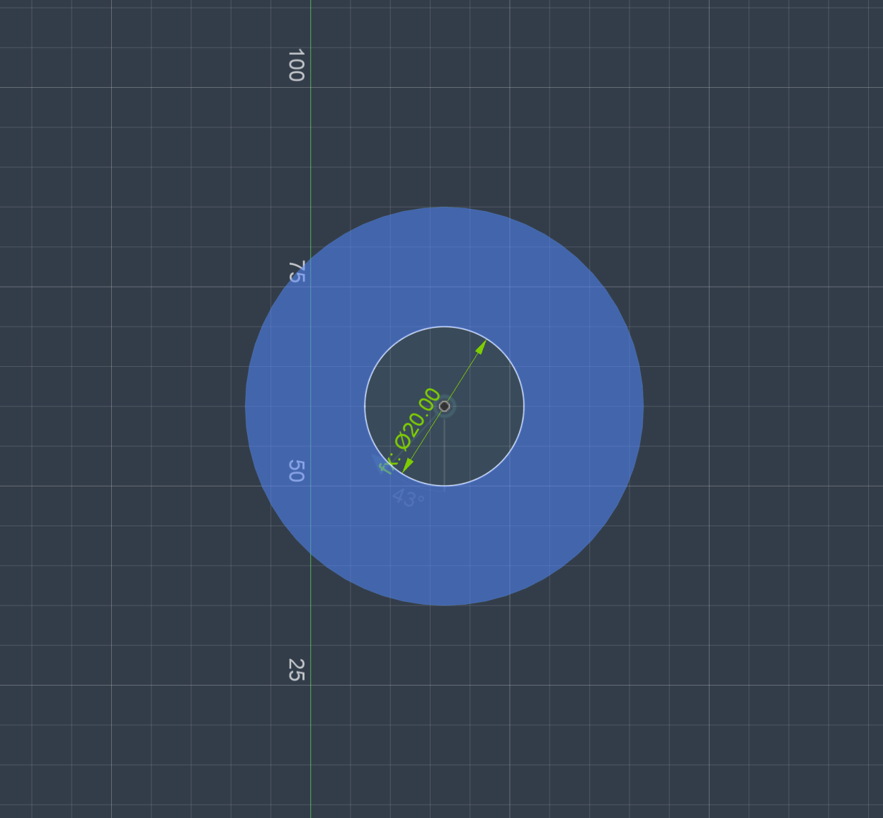
Draw the sketch profile
Use the sketch tools in the toolbar — lines, circles, dimensions, and constraints — to build the 2D profile before extruding.
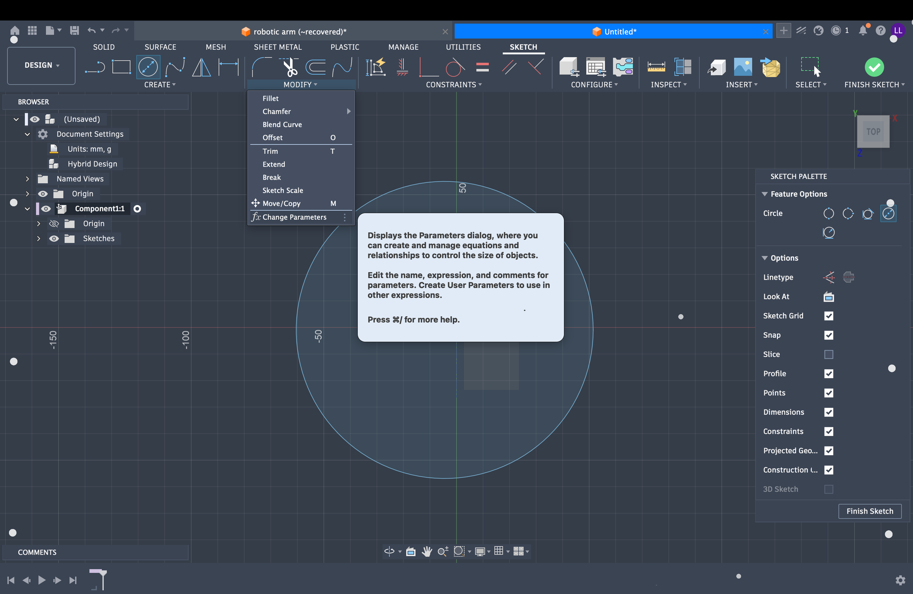
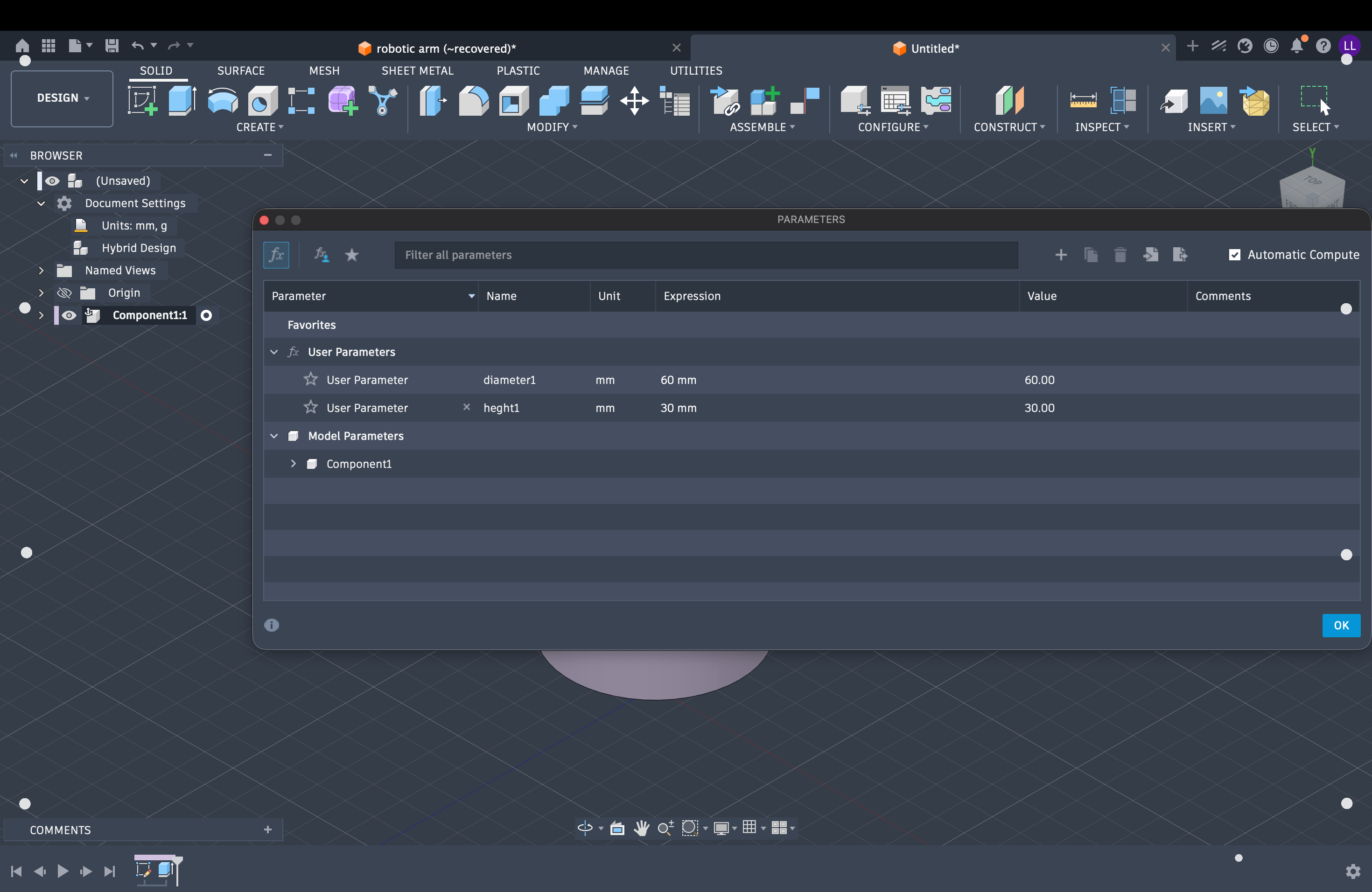
Set up parametric parameters
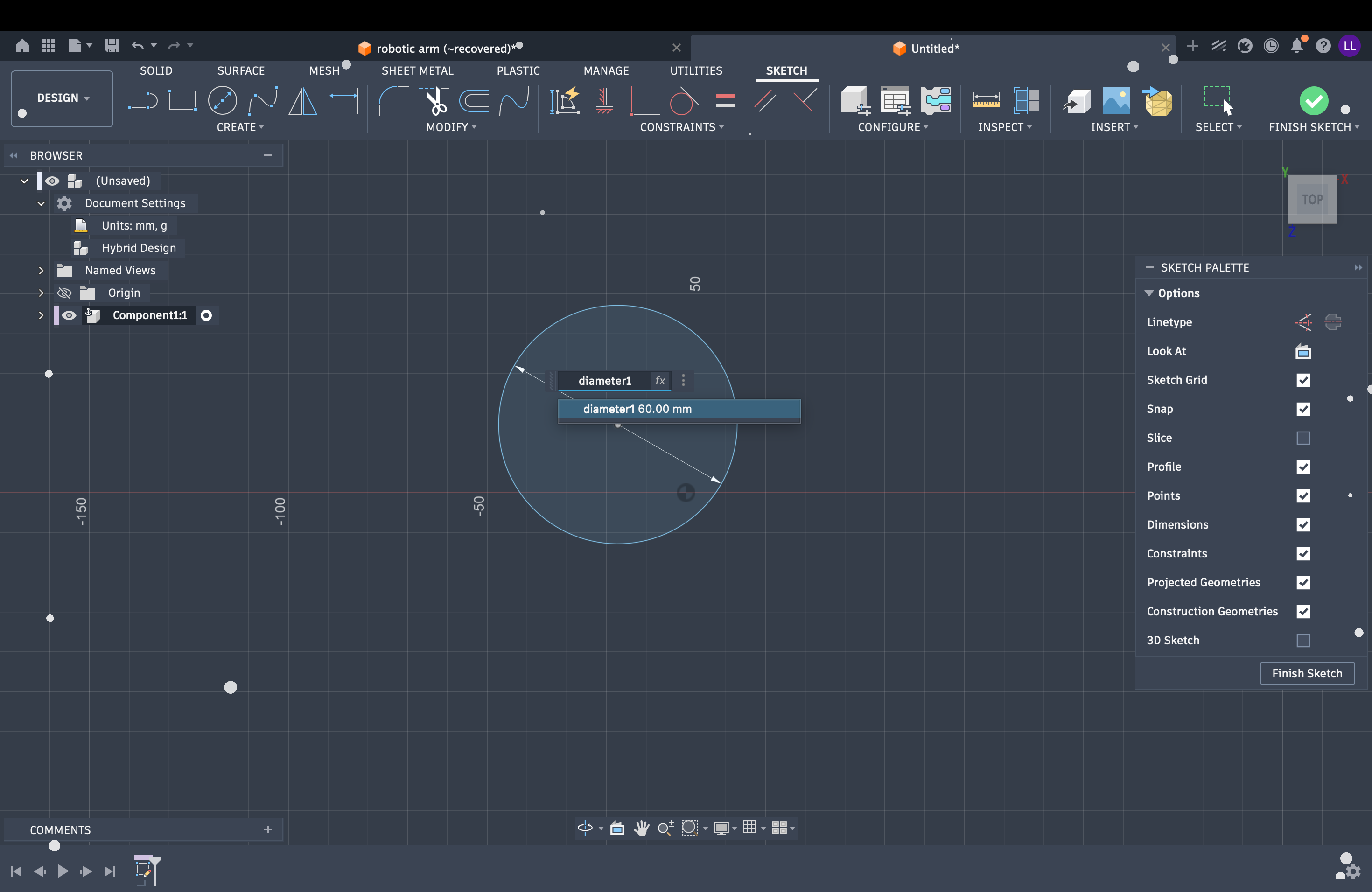
Open Modify → Change Parameters, click the + button to add new parameters, and drive sketch dimensions from the parameter table. You can also use formulas to link dependent values to independent ones — e.g. set hole spacing as Base_Diameter / 4 so the whole design updates when a single value changes.
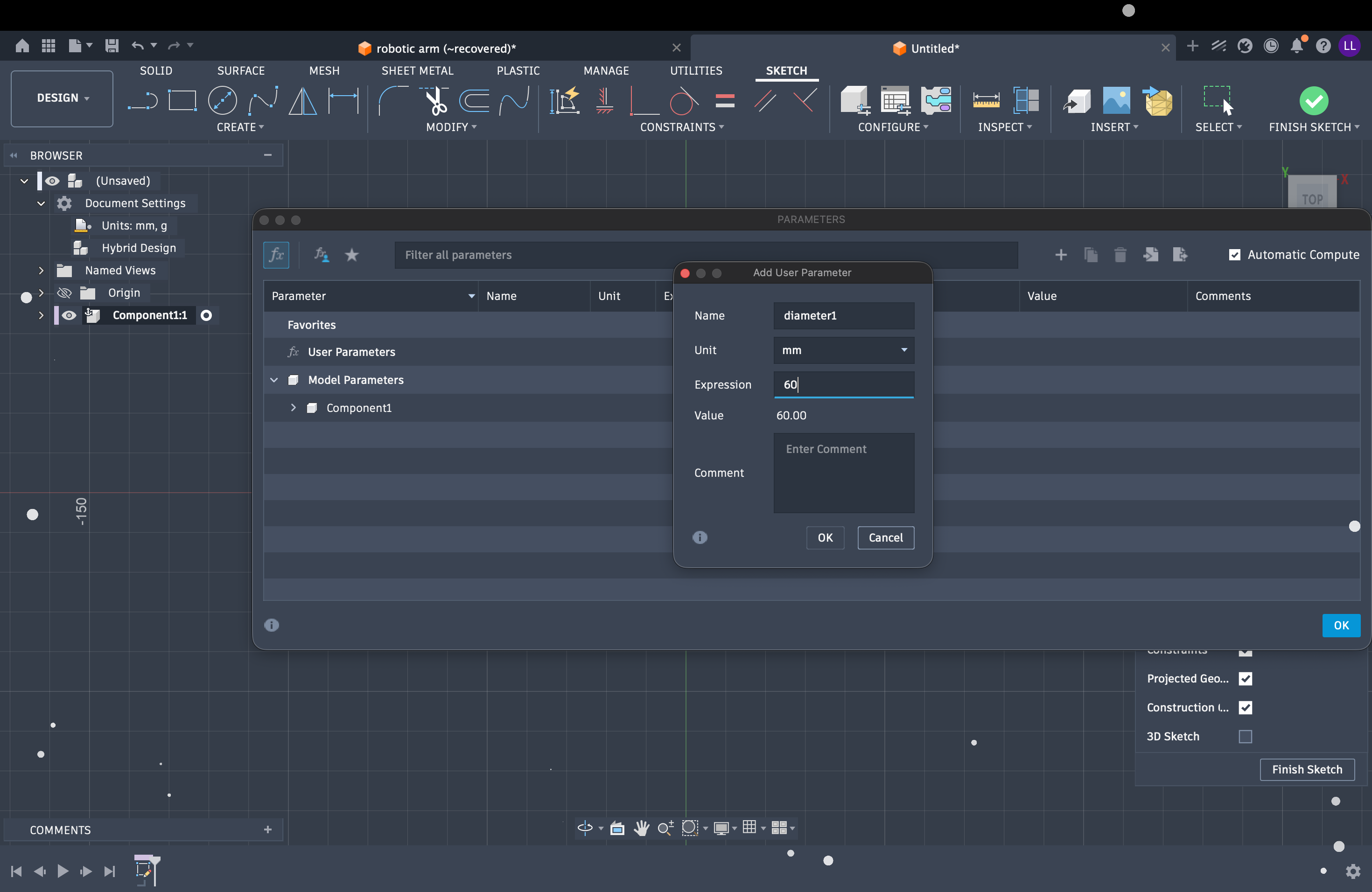
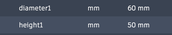
Parameter list in the design
Parameters with formulas linking dependent values
Extrude the sketch
Click Extrude, select the closed sketch profile, and set the extrusion distance. Link the extrude height to a parameter the same way as the sketch — type the parameter name (e.g. Base_Height) so the 3D body updates when the value changes.
Extrude the closed sketch profile
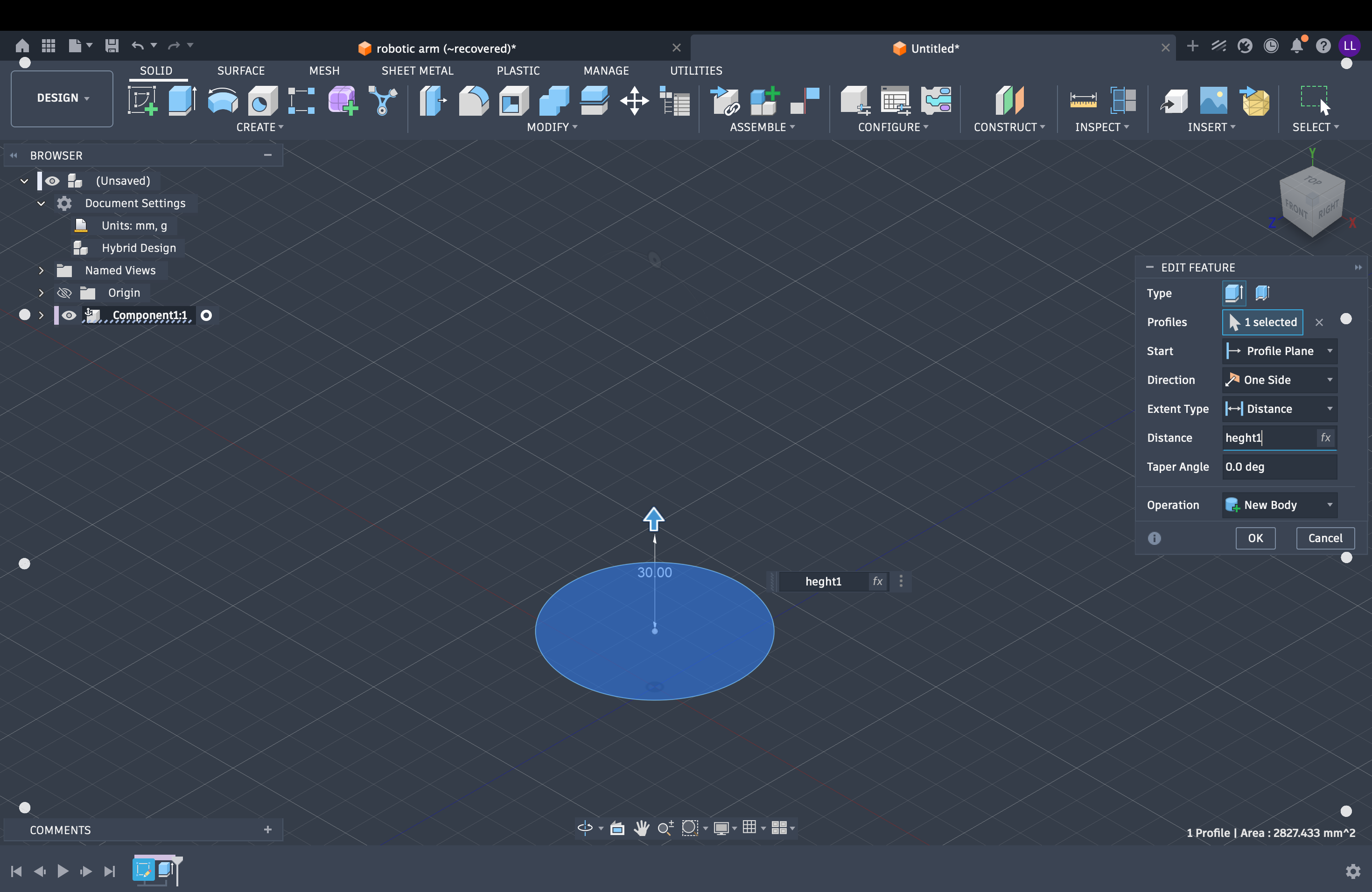
Set extrusion distance with a parameter
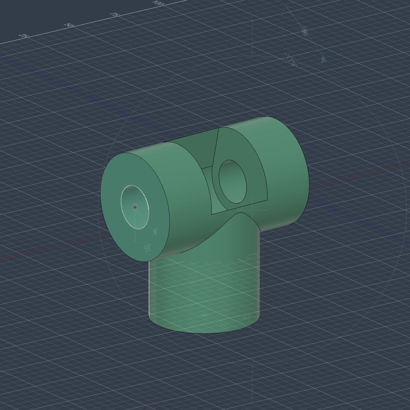
Base — add joint and complete first link
Added a central shaft on the extruded base and applied a Revolute Joint between Base and Link 1 for 360° rotation (first DOF).
Parameters: Base_Diameter, Base_Height, Mount_Hole_Diameter, Joint_Shaft_Diameter
Base side sketch
Base parameters
Base final result
Link 1 (Shoulder) — U-bracket and two joints
Created a new component, sketched a U-shaped bracket, and extruded it. Added two Revolute Joints: one to the base for horizontal rotation, one to Link 2 for vertical pitch.
Parameters: Link1_Length, Link1_Thickness, Joint_Spacing, Bracket_Width
Link 2 (Upper arm) — beam with ribs
Extruded a rectangular beam with internal ribs, then added a Revolute Joint to Link 1 for elbow motion, limited by Elbow_Max_Angle.
Parameters: Link2_Length, Link2_Width, Link2_Height, Rib_Thickness, Elbow_Max_Angle
Link 3 (Forearm) — lighter distal link
Modeled a smaller beam with cable channels and prepared the wrist mount before connecting to Link 2 at the elbow.
Parameters: Link3_Length, Link3_Width, Cable_Channel_Diameter, Wrist_Mount_Offset
Wrist assembly — pitch and roll
Built a compact housing with two orthogonal Revolute Joints for wrist pitch and roll, plus an end-effector mount.
Parameters: Wrist_Housing_Diameter, Wrist_Pitch_Range, Wrist_Roll_Range, End_Effector_Mount_Diameter
End effector base — tool mount and 6th DOF
Extruded a circular tool-mounting base with retention features, then added the final Revolute Joint for independent end-effector rotation (sixth DOF).
Parameters: End_Effector_Base_Diameter, Tool_Mount_Pattern, Retention_Feature_Depth, Rotation_Range
3. Modular Box Integration
Revisited the modular box from Week 3 and made it parametric:
- Fitment: Joint clearances controlled by parameters (
Joint_Clearance,Material_Thickness) - Scalability: Box size adjustable via parameters (
Box_Length,Box_Width,Box_Height) - Quick Changes: Can try different sizes without recalculating joints
📦 Design Deliverable
Parametric 6-axis robotic arm assembly — full Fusion 360 source file with all components, joints, and parameters.
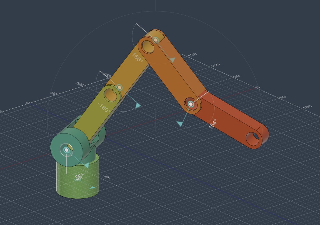
Robotic Arm — parametric CAD model (Final Project draft)
Download robotic-arm.f3d📝 Assignment Notes
Parametric modeling worked well for this project. Key benefits:
- Quick Changes: Modify parameters instead of editing sketches
- Consistency: Related dimensions stay synchronized
- Easy to Maintain: Clear structure and naming
- Manufacturing Ready: Can quickly generate different sizes
All 6 components respond to parameter changes while keeping joints and assembly correct. This will help with future development.