Mechanical Design, Machine Design
Week 12 Assignment
3D typewriter (volumetric writing machine)
We are building a three-dimensional “typewriter”—a machine that writes in space. It refines and extends the concept developed last year by the UNNC Fab Lab team, with stronger software design and a more capable control experience. The system combines 3D-printed mechanical parts, stepper motors + servo for motion, a Marlin-based controller, and G-code as the machine command language.
UNNC Fab-Lab 2026 intro
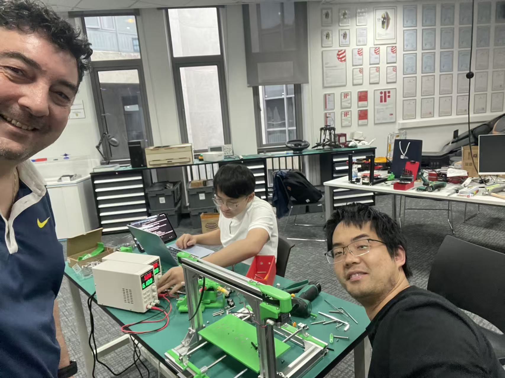
Team: Le Li, Loïc Faulon
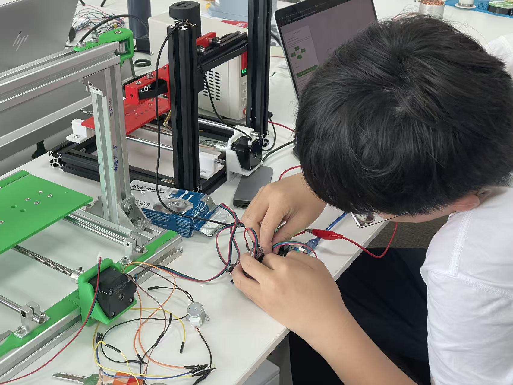
- Le Li — software & electronic control — design and debugging.
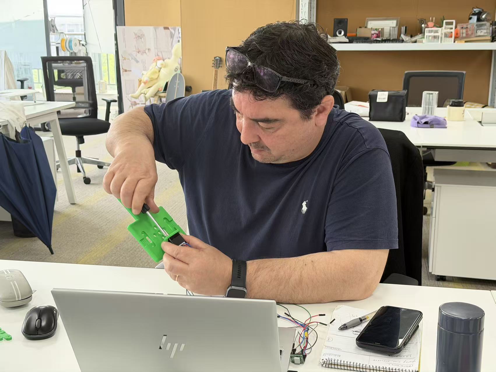
- Loïc Faulon — structural engineering — design and debugging.
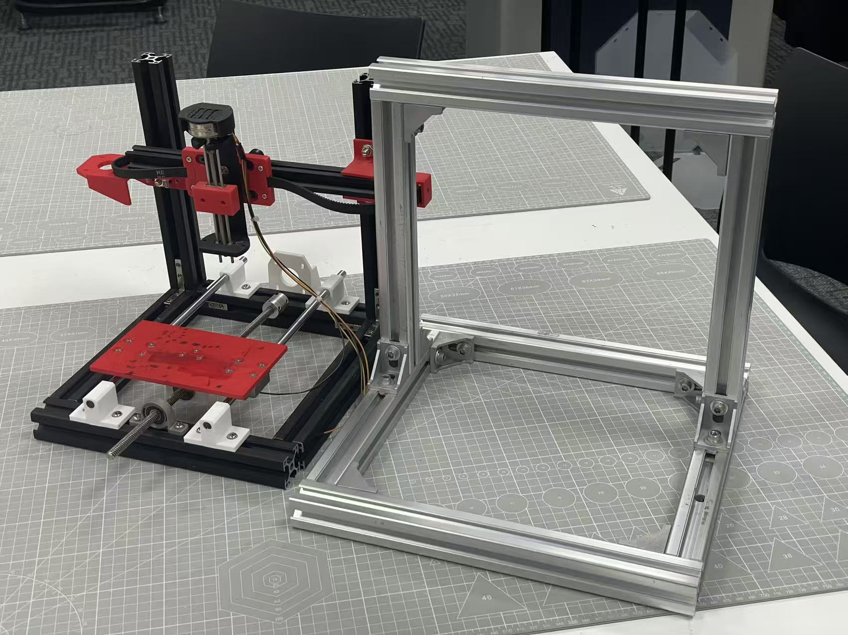
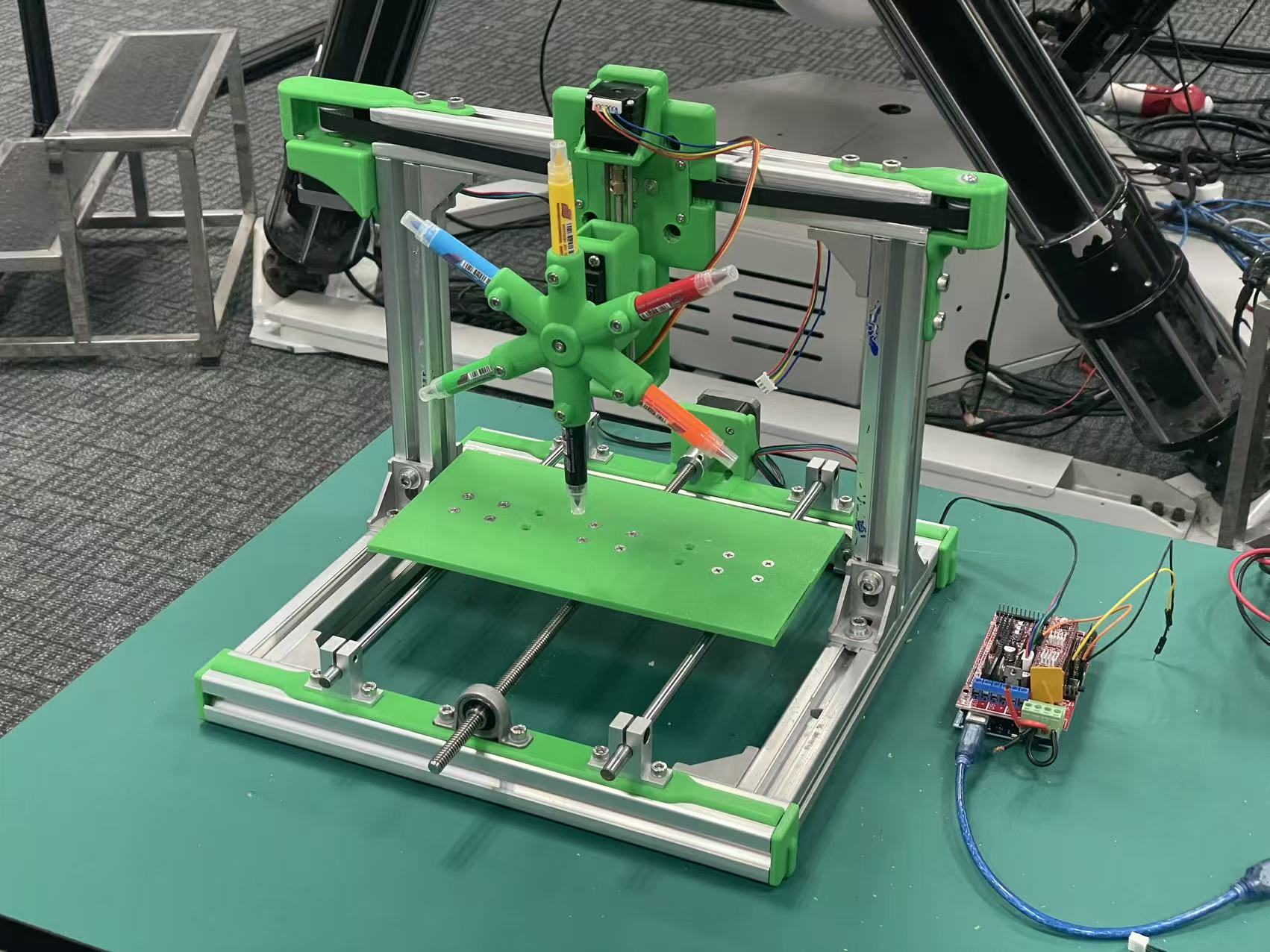
Process photos from our build:
Bill of materials (BOM)
Quantities and parts match our UNNC Fab Lab 3D typewriter build.
- Aluminum extrusion
- NEMA 17 (42 mm) stepper motors — ×2
- 28 mm reduction (geared) motor — ×1 (replaces a smaller NEMA “28”-class stepper in the initial plan; rationale to be added in a later update)
- MG996R servo, 360° continuous-rotation (pen carousel)
- 3D-printed parts
- Two sets of smooth rods + lead screws (linear axis hardware)
- One set of timing pulleys + belt
- Soft-tip watercolor / brush pens
- RAMPS 1.4 shield (motion control, stacked on the Mega)
- Arduino Mega 2560 (host MCU for RAMPS)
- External power supplies — ×2 (e.g. separate rails for motion drivers and logic / accessories, as required by the build)
- Dupont jumper wires (assorted lengths, for breadboard and shield interconnections)
Final results
Software, videos, and the on-machine run for this week’s 3D typewriter milestone. (The control UI also appears on the home page.)
Machine control software
Browser-based control: Web Serial, axis setup, tool/colour, 3D path preview, and G-code streaming to Marlin.
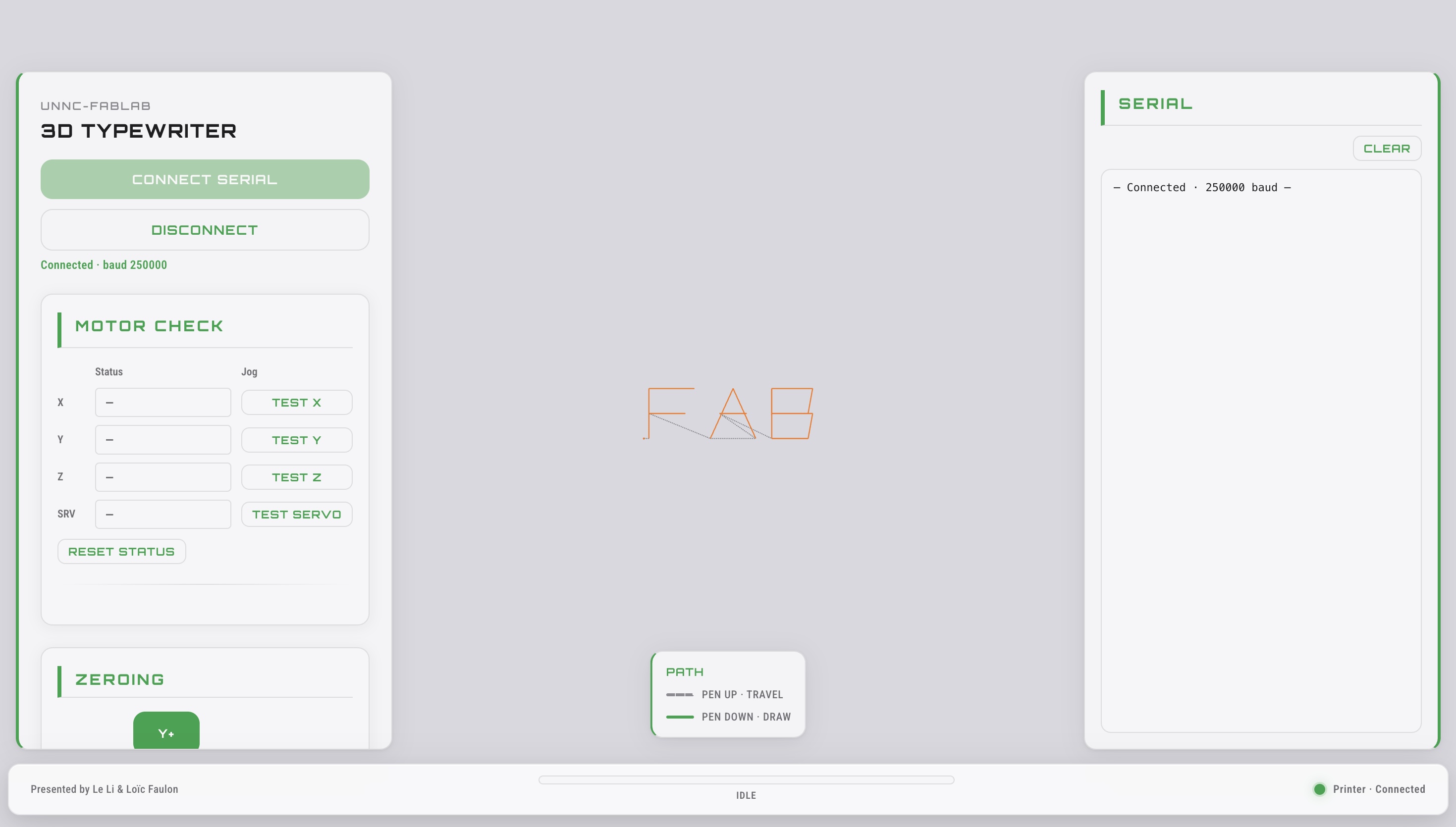
- Web Serial — Connect in Chrome or Edge; no install, direct talk to the controller.
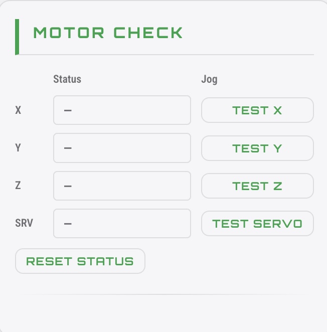
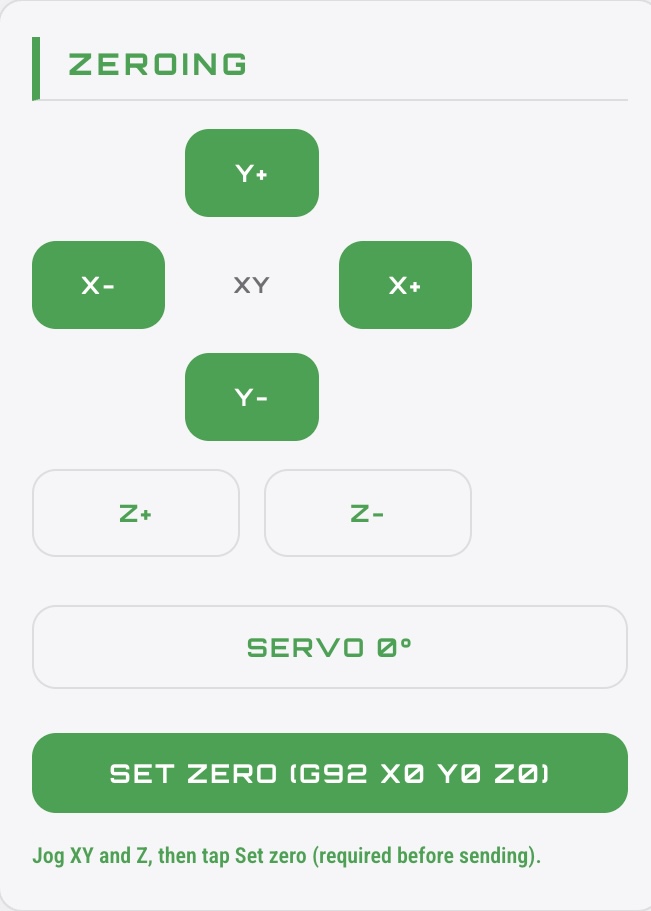
- Setup & motion — Axis tests, jogging, servo alignment, and set work zero before you run.
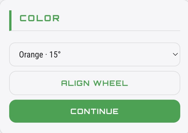
- Tool & color — Pick paint channels and align the wheel so the right tool is at the work.
- Path & preview — Type a word, see the 3D toolpath and motion before sending G-code.
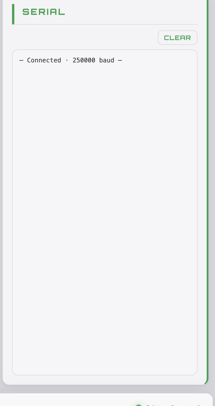
- Send & feedback — Stream commands with clear status and a serial log for troubleshooting.
Videos
Single on-machine clip for this week’s milestone.
Problems and solutions
Two limitations visible in the videos above are listed below. Each item states the problem and the solution we are applying (or have applied as a short-term fix).
1. Z-axis motor torque and pen-up
Problem. Writing control in the clip is not yet ideal. The Z axis was driven by a compact NEMA “28”-class stepper with insufficient torque to raise the tool reliably for pen-up / travel—so the machine cannot “lift the pen” as intended in software.
Solution. Replace the Z motor with a 28 mm planetary reduction (geared) motor so the axis has enough torque to execute a dependable pen-up before XY travel.
2. Clearance between the printed base and the pen tips
Problem. The stack-up we designed between the 3D-printed base and the pen tips at their motion limits was miscalculated. At full travel the mechanism risked binding or the wrong working height, which shows up in the video.
Solution (interim). We added a shim / spacer under the relevant parts so the machine could run as in the recording.
Solution (next revision). Correct the CAD and frame dimensions so the designed assembly matches the required clearance without that extra packing.