12 : Mechanical and Machine Design<
Week Summary<
This week’s assignment is to design and build a machine. This is a group assignment. After discussing the different ideas we had and were proposed to us, we agreed to make a kinetic sand table. Many examples can be found. Here is one.
A general overview and summary can be found on the group page :
Below you may find the group members webpages to find more details about a specific part of the project :
Elodie : Global structure and 3D pieces design (motor holders, feet…)
Michel : Stepper motors control and PCB design
Jonas : Design of the trolley for the magnet and aluminum frame assembly
Fabio : Enclosure for the sand and magnetic ball
Learning Outcomes<
What did I learn this week ?
- Machine Design :
- Machine architecture
- Different parts and steps of machine designing
- Building :
- Using Timing Belts
- Building Core XY structure
- Video Editting
- Using KdenLive for video cutting
Assignments<
This twelfth week's asignments are :
- Group :
- Design a machine that includes mechanism + actuation + automation + application
- Build the mechanical parts and operate it manually
- Document the group project
- Individual :
- Document your individual contribution
1. Theory<
1.1. Machine Definition<
Wikipedia defines a machine as :
a thermodynamic system that uses power to apply forces and control movement to perform an action.
Here, we will restrict this definition by considering a machine as :
a device that moves an end-tool using mechanisms, drivers and control systems.
1.2. Machine Architecture<
A machine architecture can be divided in two stacks :
| Mechanical Stack |
|---|
| Actuation : Injects energy into the system |
| Transmission : Converts rotation into linear motion |
| Guides : Dictates the exact path of the force |
| Structure : Absorbs the reaction and maintains geometry |
Control Stack :
- Planning and UI : Generates toolpaths and UI for interaction
- Coordination and Communication : Synchronizes mutliple axes and communicate with UI
- Motion Control : Executes precise movement and interpolation
- Power electronics : High-power interface that drives actuators
- Actuators
1.3. Machine Design<
Tool Head :<
-
What does it do ? (Cut, Mill, Extrude, Burn, Dispense Candies, ...)
-
What constraint does the tool head require ? (Slow motion, Lot of force, Precision, Superfast, ...)
Mechanical System :<
-
What motion mechanism ? (Lead and screw, Rack and pinion, Timing belt)
-
What motion restriction ? (Shaft, Rails, ...)
-
Parallel Kinematics ? (One motion requires multiple motors)
-
Makes everything hold (Frame)
-
Machine enveloppe : either defined by the required workplace or by an exterior constraint
Sensors and actuators :<
-
How do you actuate your machine ? (Sensors, Controllers, ...)
-
How do you control the machine ? (Interface, Software, Application, ...)
1.3. Mechanical Parts<
| Fasteners | Picture |
|---|---|
| Buttonhead screws | 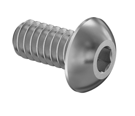 |
| Flathead screws | 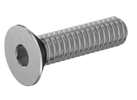 |
| Shoulders screws | 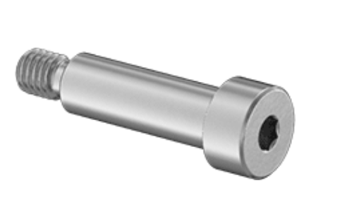 |
| Heat-set inserts | 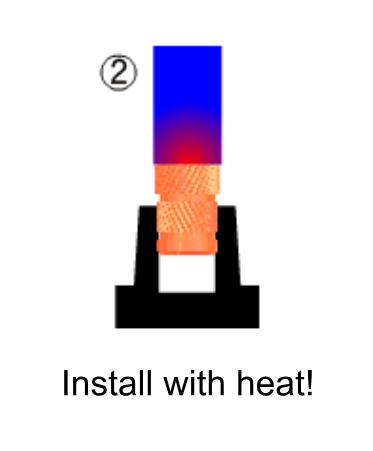 |
| Dowel pins | 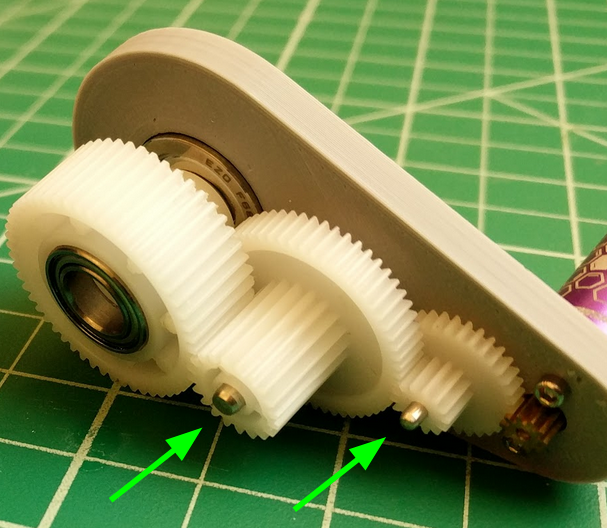 |
| Small L-brackets | 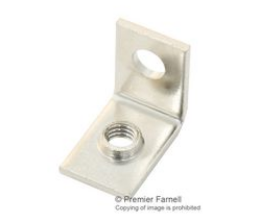 |
| Push-in plastic rivets | 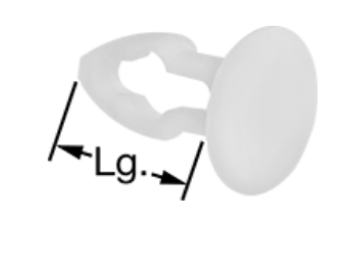 |
| Mechanisms | Picture |
|---|---|
| Revolute Joints | 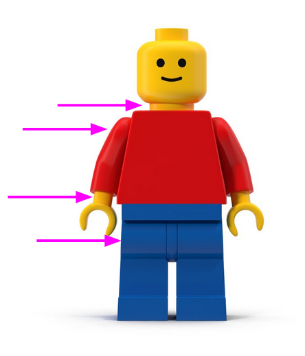 |
| Prismatic Joints | 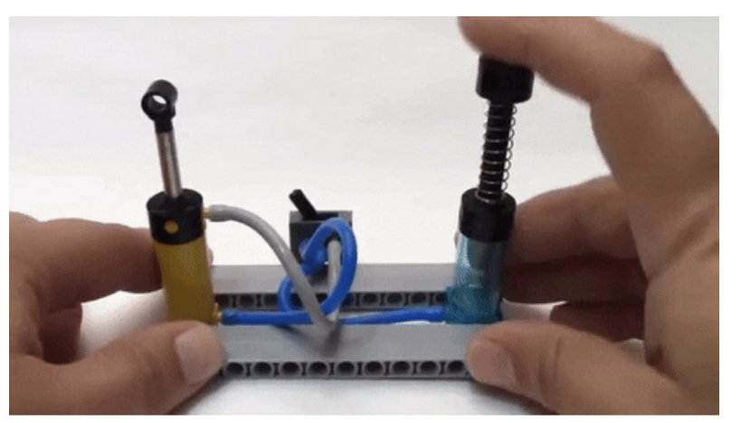 |
| Ball-and-Socket Joints | 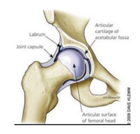 |
| Universal Joints | 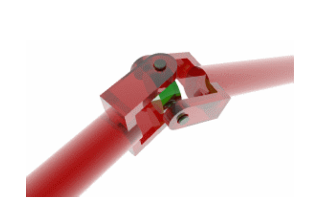 |
| Cams | 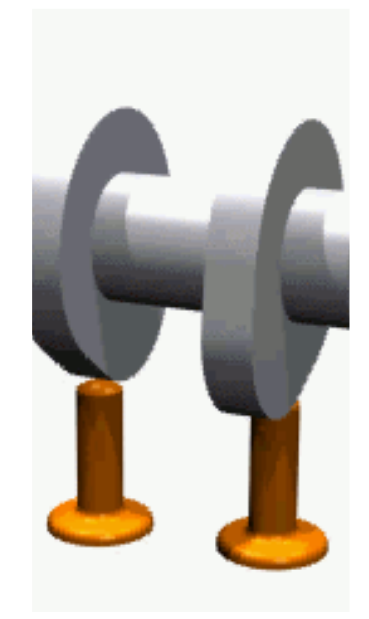 |
| Linkages | 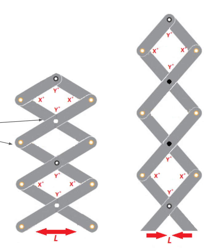 |
| Gears | 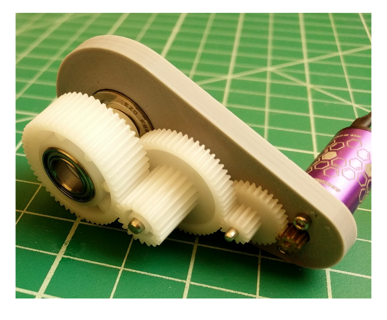 |
| Bearings | 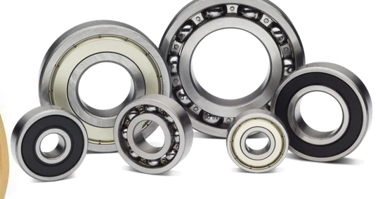 |
| Compliant Mechanisms |  |
1.5. Control<
Open-loop and Close-loop<
Open-loop system : Predictable machine system, no need to control the output
Close-loop system : Unpredictable system, requires to reconsider the actuation depending on the output
Control methods<
Bang-bang control (two thresholds)
PID control
A lot of different control methods exist
Control architecture<
Centralized : Everything is controlled by one controller
Extended : Centralized + one smarter tool head
Distributed/BUS : Each axis has its own local controller
Daisy Chain : Controllers connected one after another in a chain
Hybrid : Combination of bus + tree + star
Virtual Machine Control : Control a virtual machine instead of a real one
Dataflow : ?
Communication<
2. Group Project Management Meeting<
2.1. Project Description<
We first discussed about potential machine ideas and Michel suggested a machine which draws on the sand : it is composed of a magnetic marble in a sandbox moved from below by a magnet whose position is controlled by motors. You may find all the inspirations on the group page.
Below you may find the raw notes of our meeting.
2.2. Meeting Notes<
Workspace<
Motion in a plane :
- circular work zone -> polar coordinate :
- an axis fixed at the center that can rotate
- a cart that rolls axis that makes the radial motion
- rectangular work zone -> cartesian coordinate :
- an axis fixed on the side that can move along one axis
- a cart that rolls on the axis makes the other axis motion
Machine Design<
Constraint : slow motion, precision
Motion mechanism : strongly depends on the work space shape, we have to decide :
- rectangular core xy
- timing belt + 2 steppers motors (for precision)
System Diagram :
- TOOL : magnet + magnetic marble
- CONSTRAINT STRUCTURE : rails
- KINEMATIC STRUCTURE : belts
- MOTORS : stepper motors
- CONTROL : centralized, RP2040, feedback = stop buttons
Prototyping steps<
-
CONCEPT TESTING :
- rectangular sand box
- sand
- magnet
- magnetic marble
-
MANUAL TESTING :
- cart
- rails
- belts system
- fasteners
-
AUTOMATION TESTING : CONTROL
Required materials<
MATERIALS for ~50cm square work space :
- 5 x 50cm rails
- 2 x 2,5 m belt
- 8 x pulleys with teeth
- 2 x pulleys (with or without teeth)
- 9 x wheels
- fasteners
Tasks distribution<
- Elodie : Feet + Sliders
- Jonas : Cart (Wheels + Holding Magnet + Pulleys)
- Michel : Control
- Fabio : Sandbox
I will then start by focusing on cart design and prototyping.
3. My contribution hero shots<
3.1. Cart Design and Build<
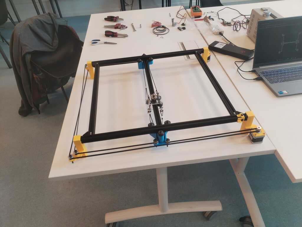
3.2. Part of Structure Building<
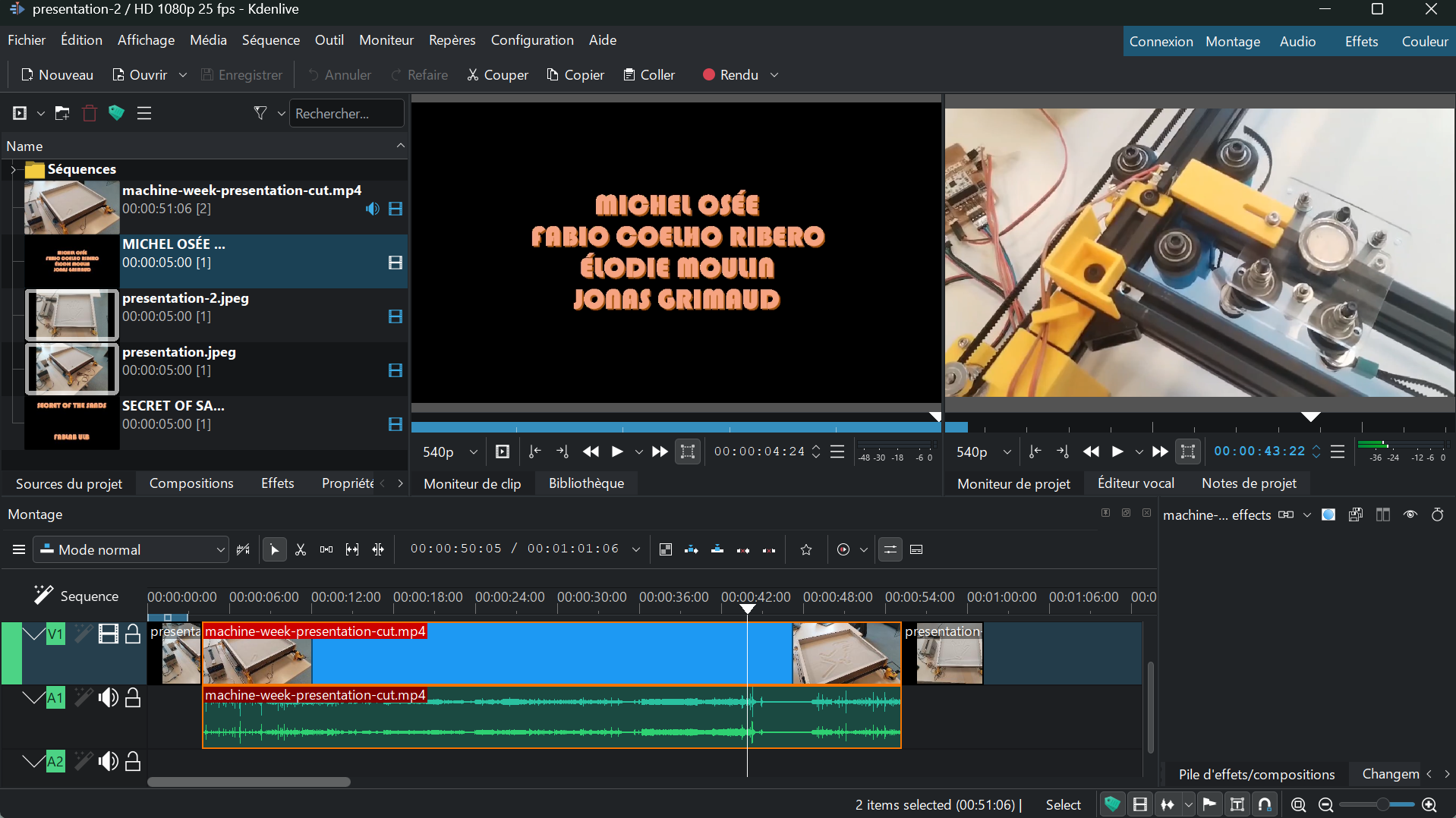
3.3. Video Editting<
4. Logbook<
4.1. Cart Design and Build<
Wheels<
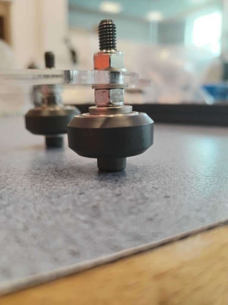
Note
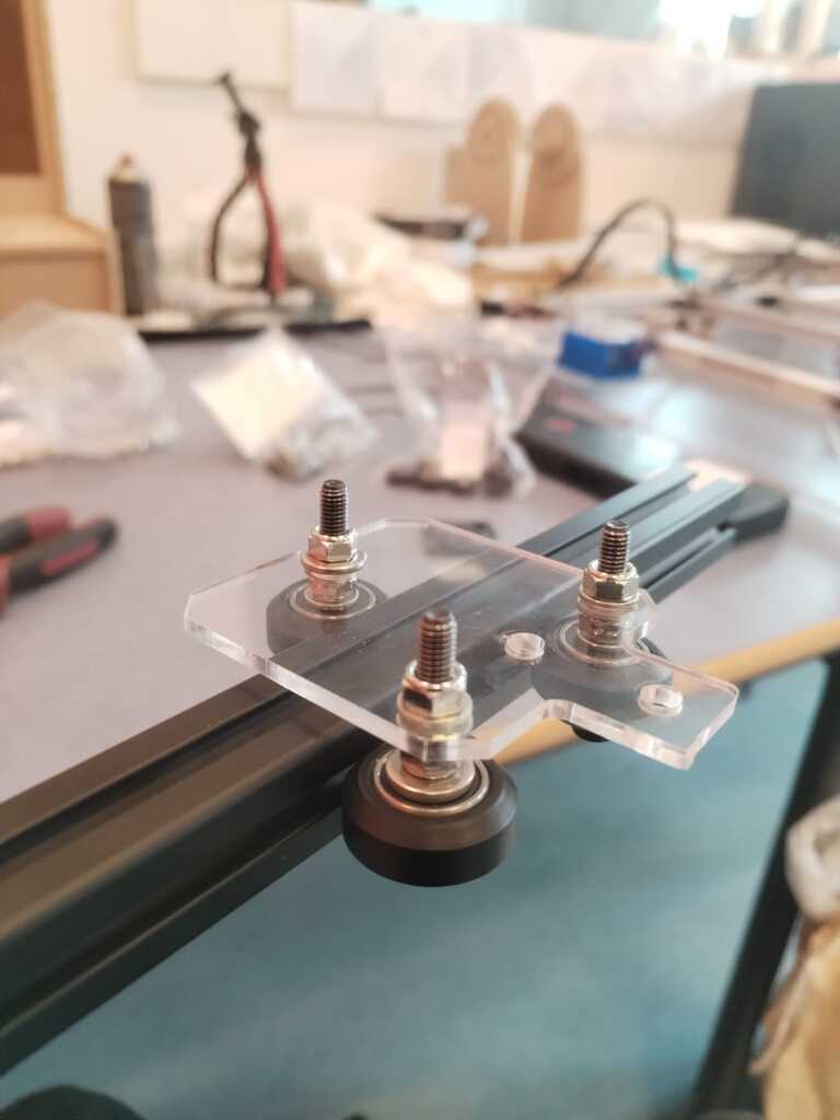
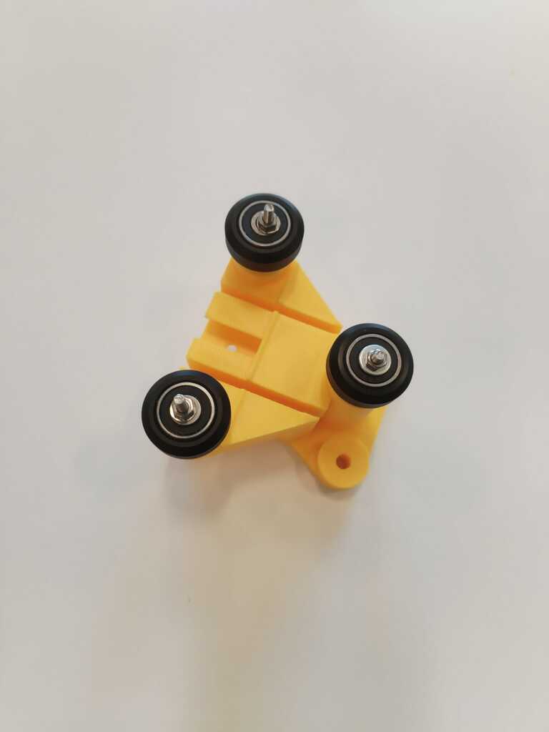
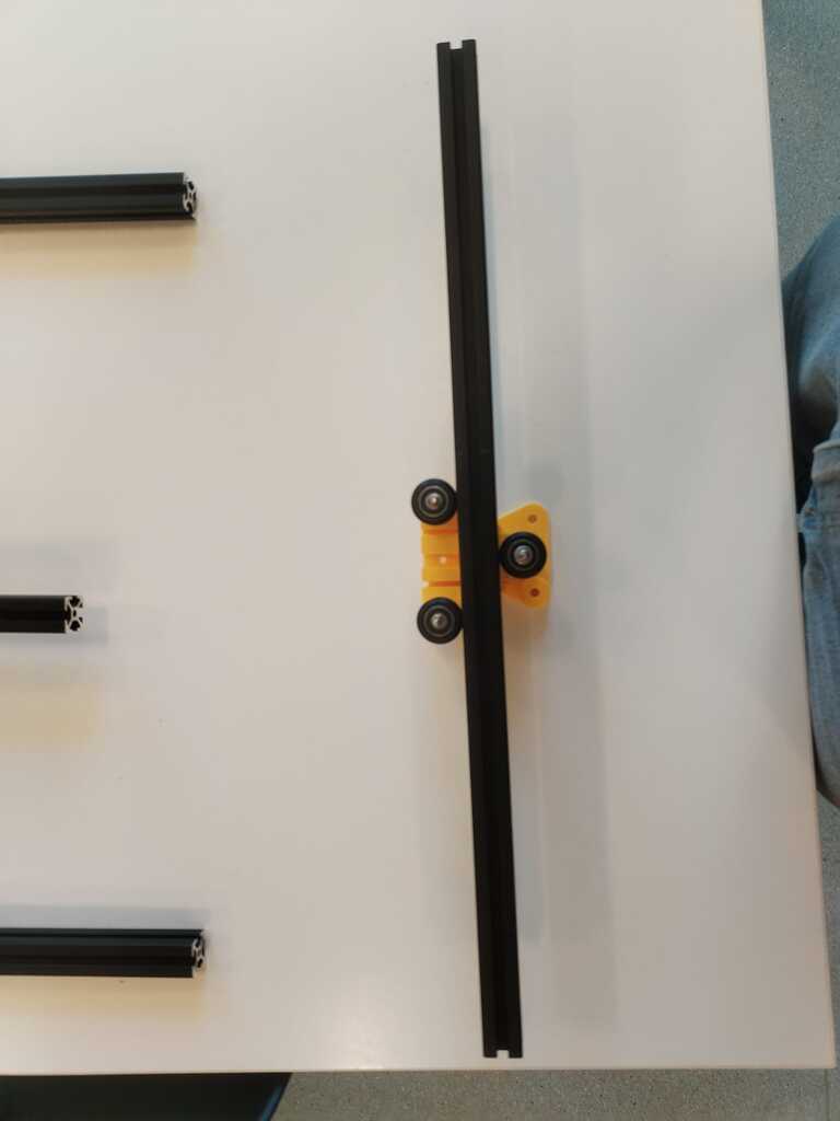
Before designing a cart, I had to understand how the wheels we had could be attached to a plate in order to slide on the aluminium extrusion. I tried this fastener combination and it seemed to work fine.
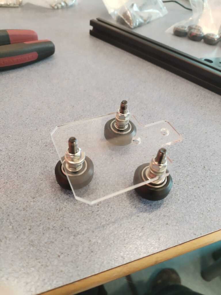
Note
I fixed three wheels on an acrylic plate I found in the Fab Lab. It was previously used for a similar project so the gap between the wheels should matche the extrusion width.
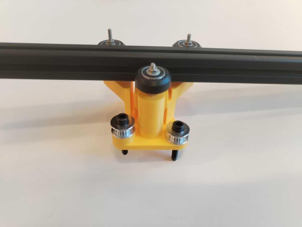
Note
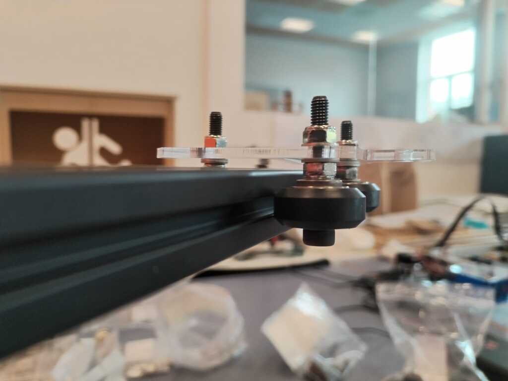
I tested the latter assumption by setting the "cart" on a rail and it worked.
Note
I checked below to see if it was bent but everything was fine.
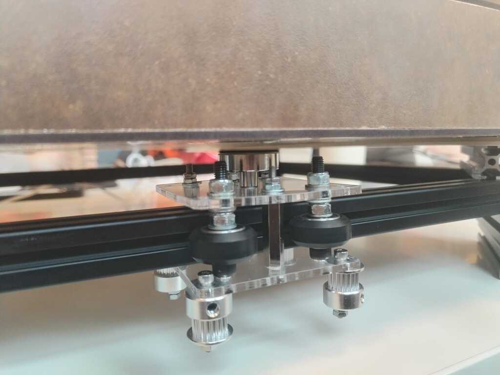
Cart Model<
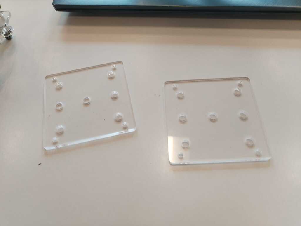
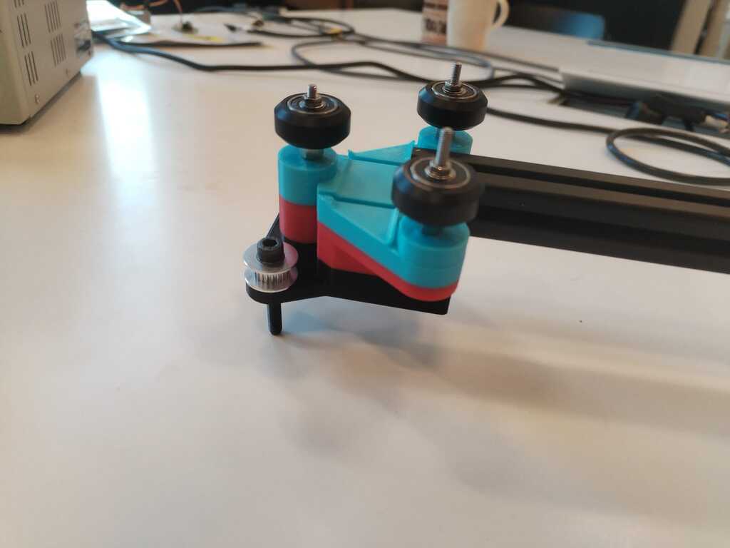
Note
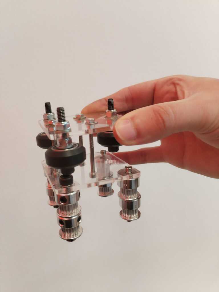
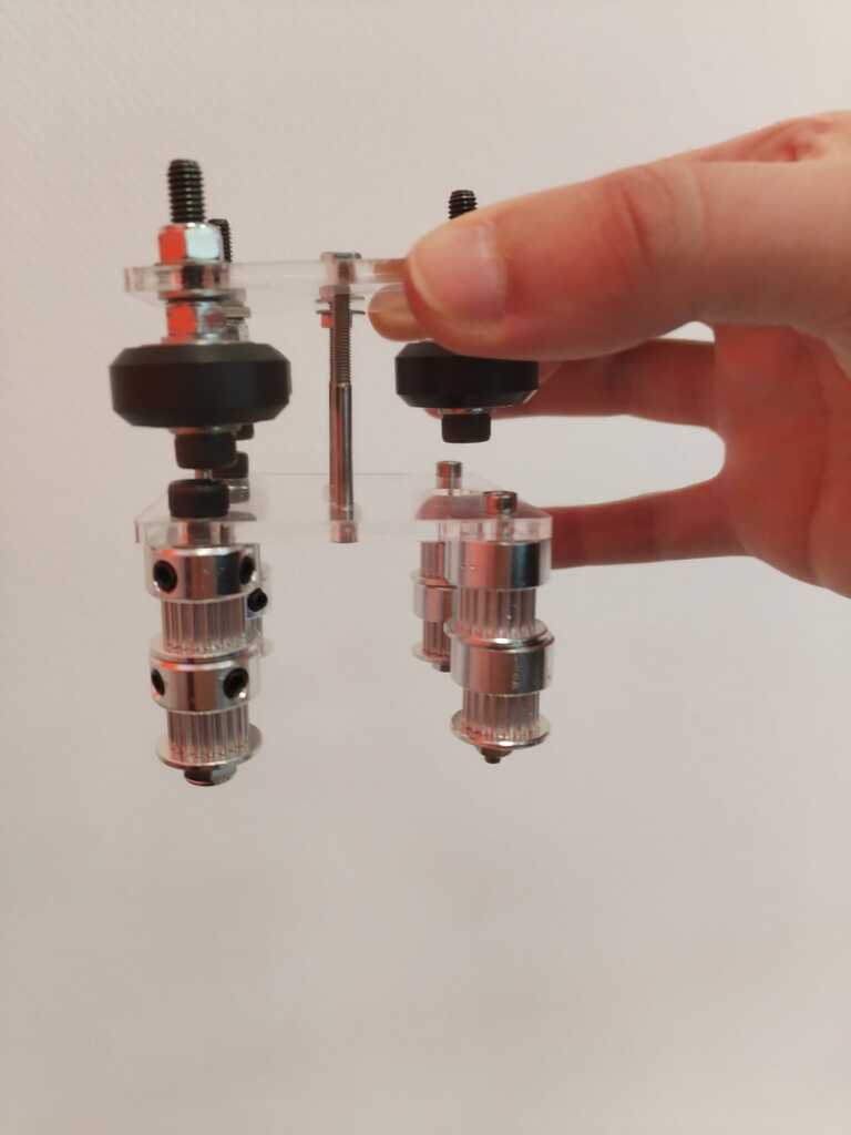
I then used a second acrylic plate to make a model of the final cart also containing fasteners for the timing belt.
Note
You can see it is not a functional prototype but just a simple model since the extrusion bar can not go through the wheels. I will have to find a way to attach the two plates without blocking the extrusion bar.
Cart Prototype 1<
Note
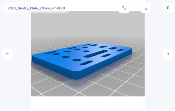
I then looked for an extrusion plate 3D model on Thingiverse to start producing my own.

Note
I converted the 3D model into a 2D file by using the OpenSCAD projection() function and exporting it into .svg. It allows me to laser cut the piece in acryclic.
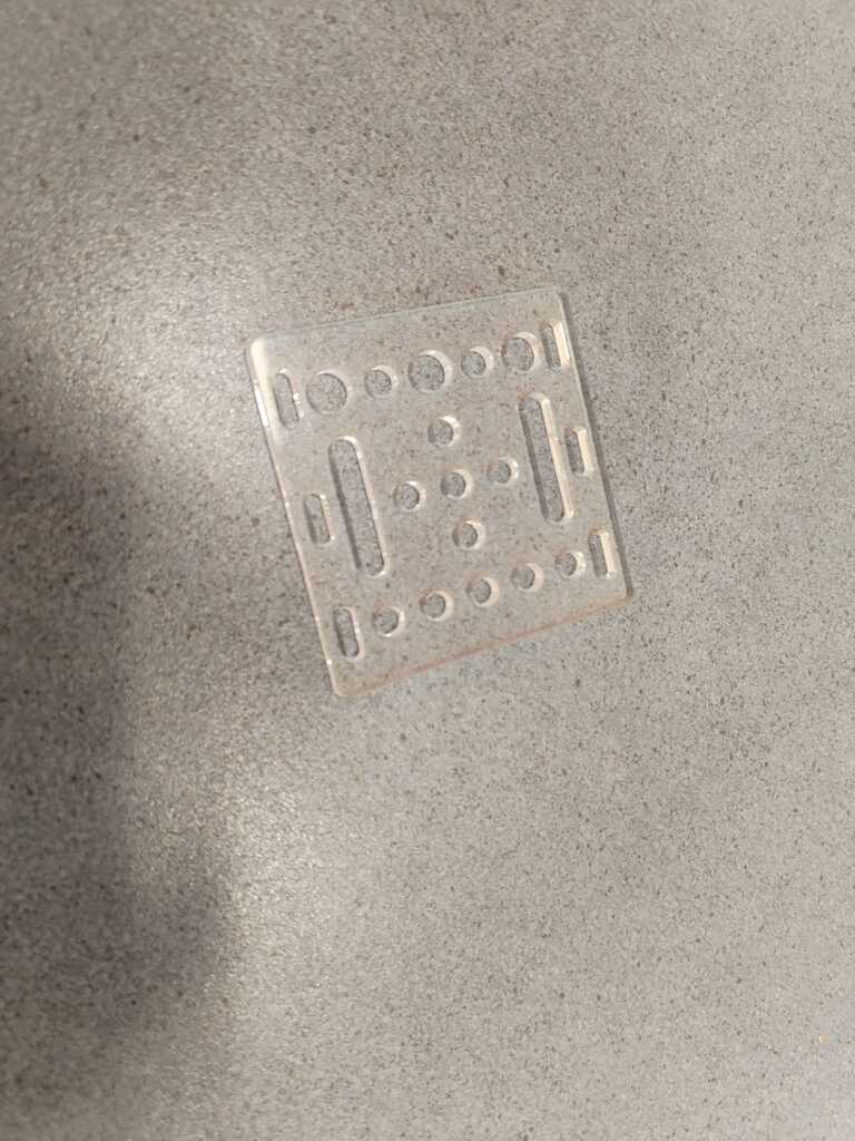
Note
Here is the result of the laser cut piece. I cut two of them in order to get the upper and lower plates.
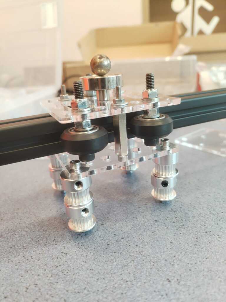
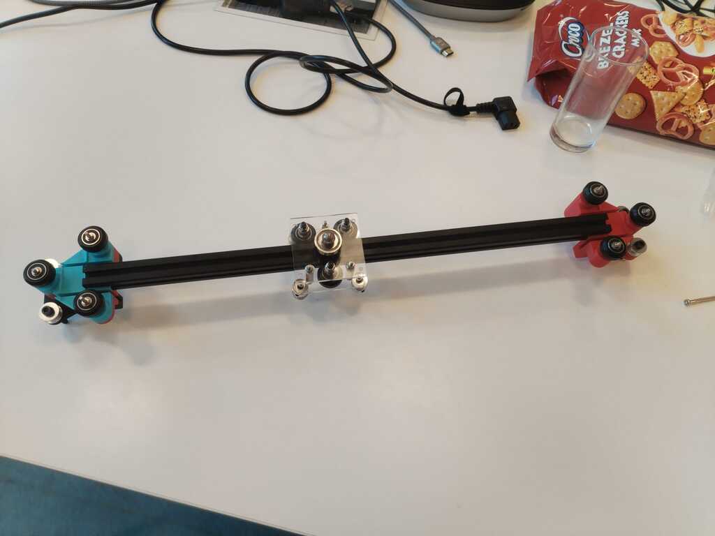
Note
I built everything in the same way as the previous model however the screws are now better placed and let room for the extrusion bar to be inserted. Here is then the first cart prototype.
Note
We tested it a bit and it unfortunately fell on the floor and broke. Here is a picture of the broken plate.
Cart Prototype 2<

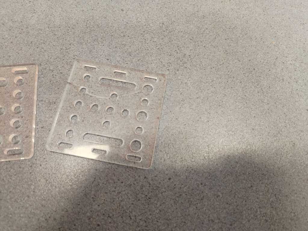
Note
I took advantage of this opportunity to remake the .svg file by filling the useless holes and moving the screws holes at a better place.
Note
Here are the resulting cut pieces.
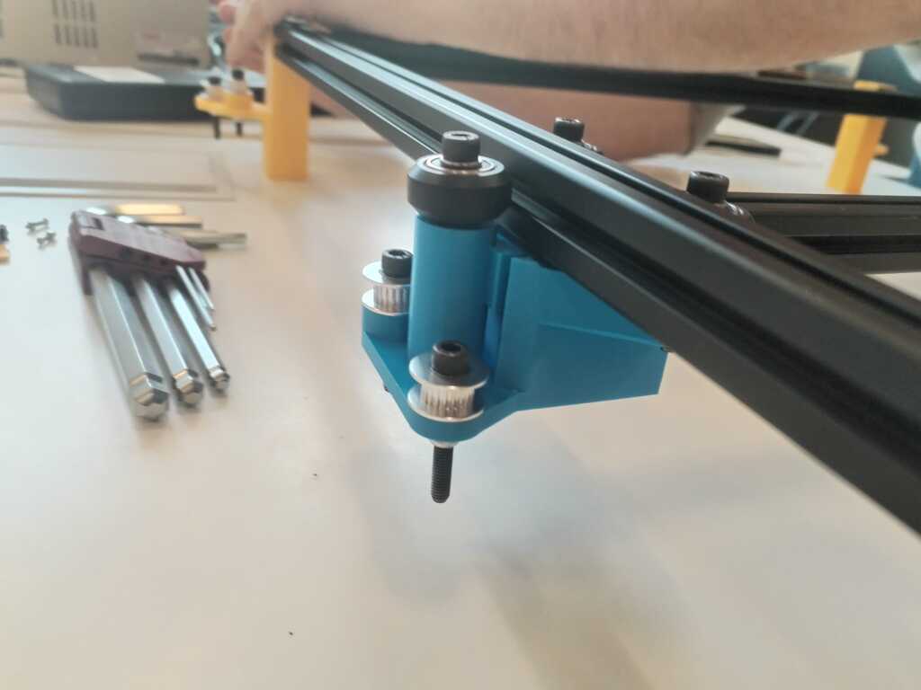
Note
Here is our final cart !
4.2. Structure Building and Testing<
Structure Building 1<
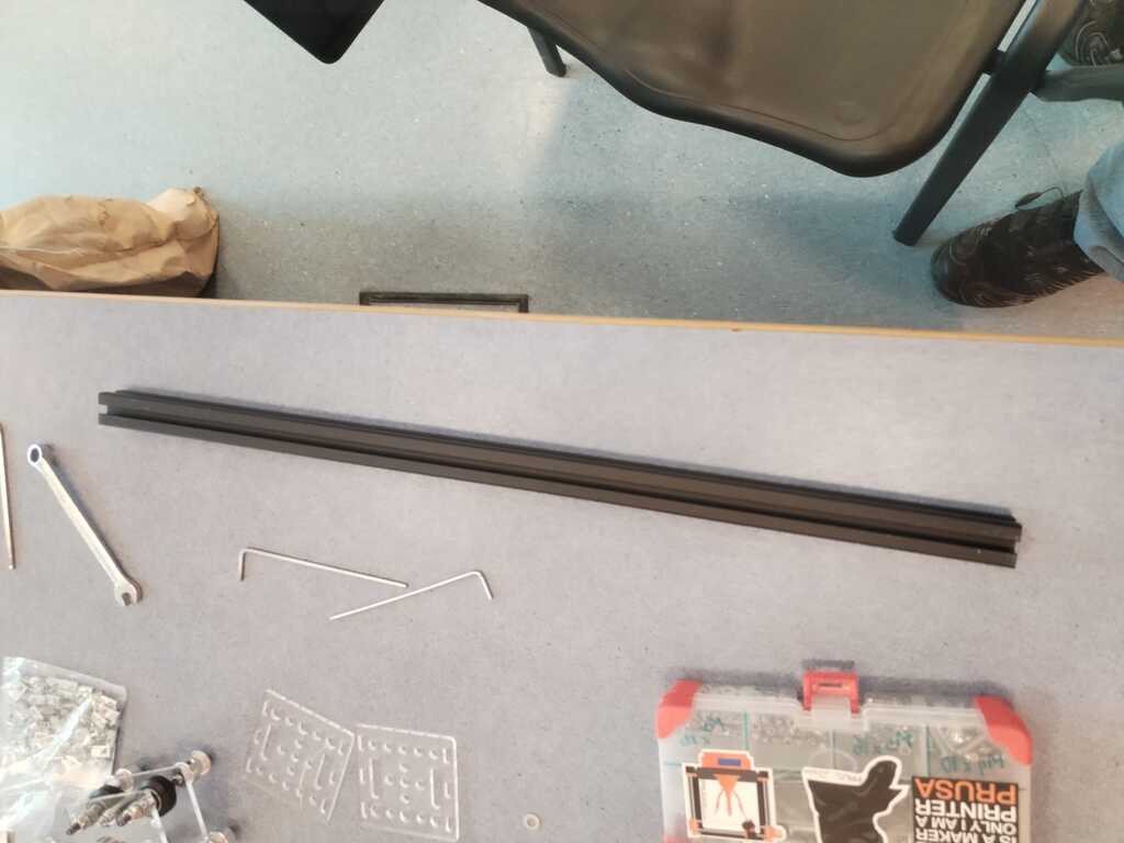
Note
As mentionned before, the structure will be built using extrusion bars like this one.
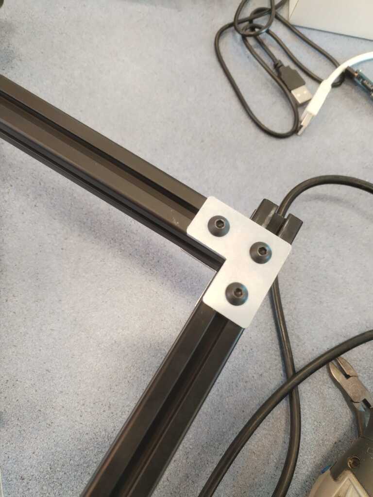
Note
We started using L-fastener to attach them together.
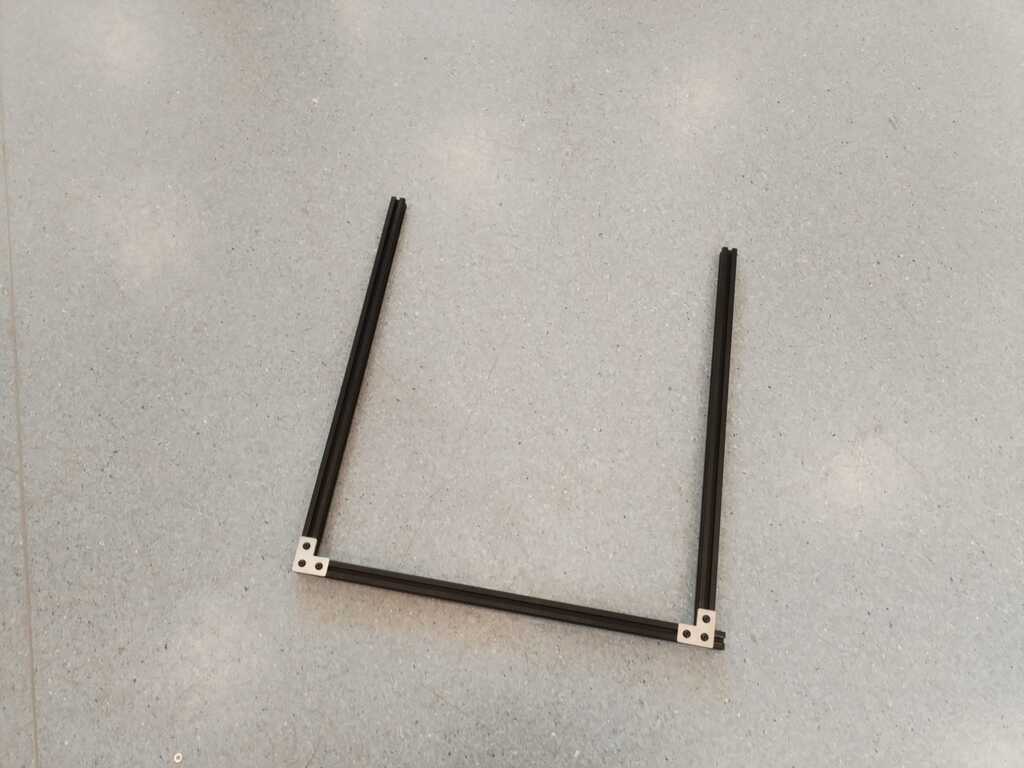
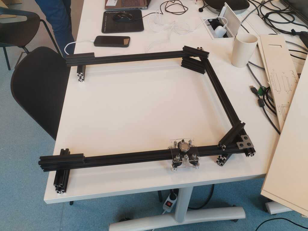
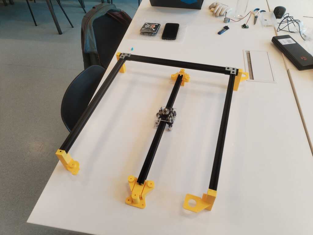
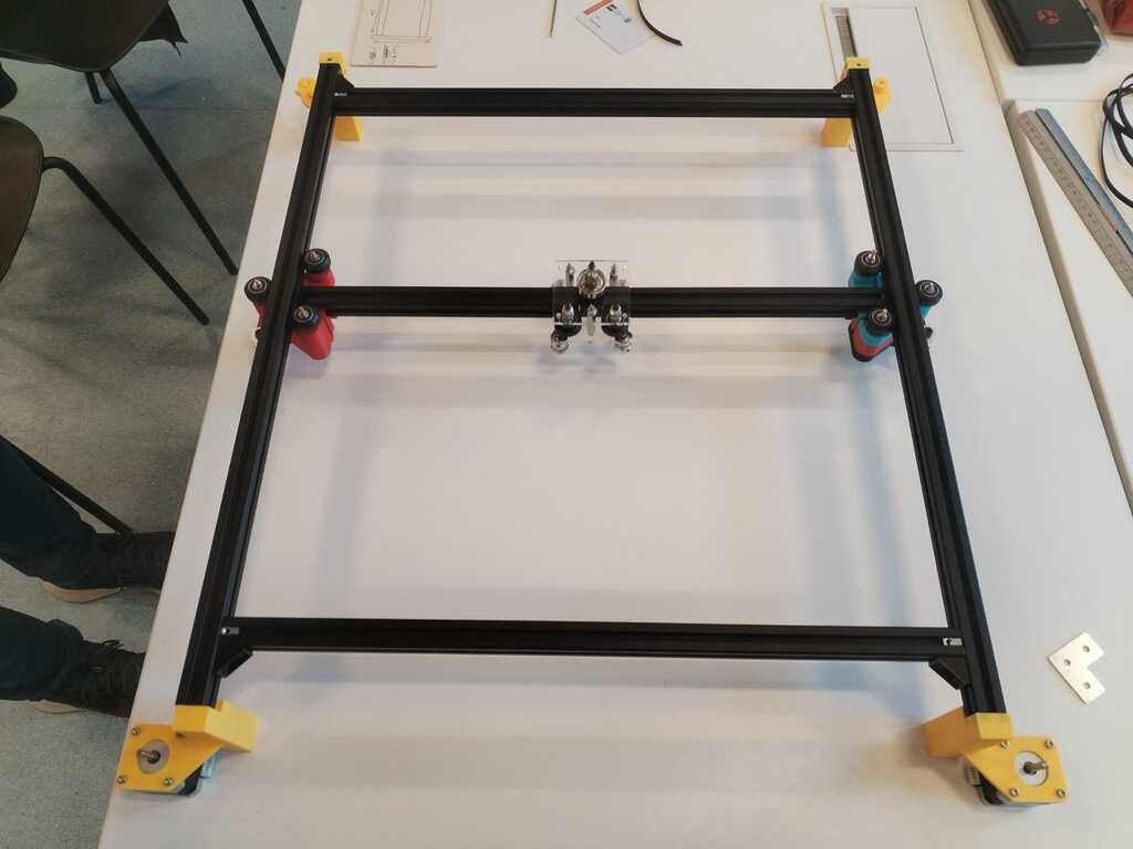
Note
We built a U-shape structure and waited for the sliders to be ready before keeping building.
Feet 1<
Note
The first foot prototype was ready so tested it.
Note
Here is a side view. It is quite good but we are afraid that the hole where the extrusion is inserted is not deep enough.
Concept Testing<
Note
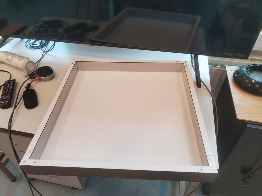
At this point, the sandbox was ready hence we had enough elements to test the core concept : moving a magnetic marble with a magnet on a cart through a wood box.
Note
We started installing everything for the test and installed small extrusion bars on the corners to elevate the sandbox so its bottom does not touch the cart's magnet.
Note
Extrusion bars were a bit too high and the sandbox bottom was therefore too far away from the magnet. We replaced them with thin cardboard sheets.
Note
Cardboard sheets were good. It elevates the sandbox enough for the magnet to not touch its bottom and too much for the marble in the sandbox to be sensitive to the magnet.
Feet 2 and Sliders 1<
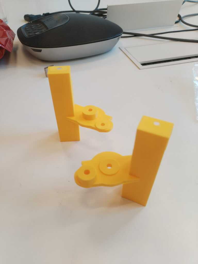
Note
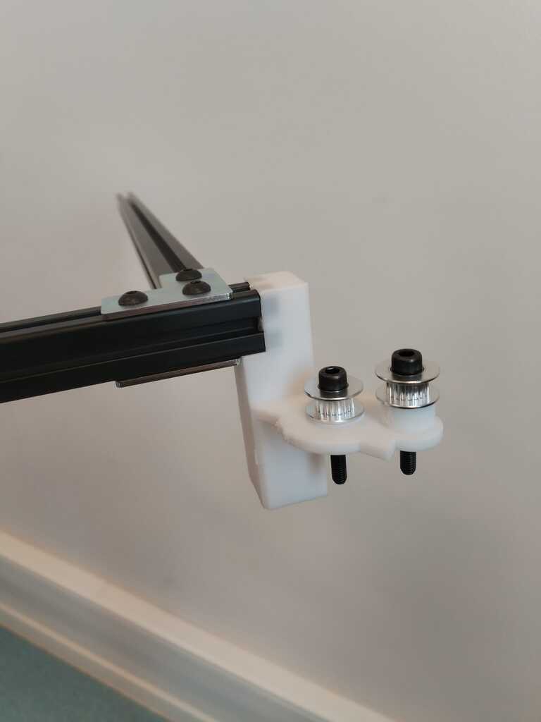
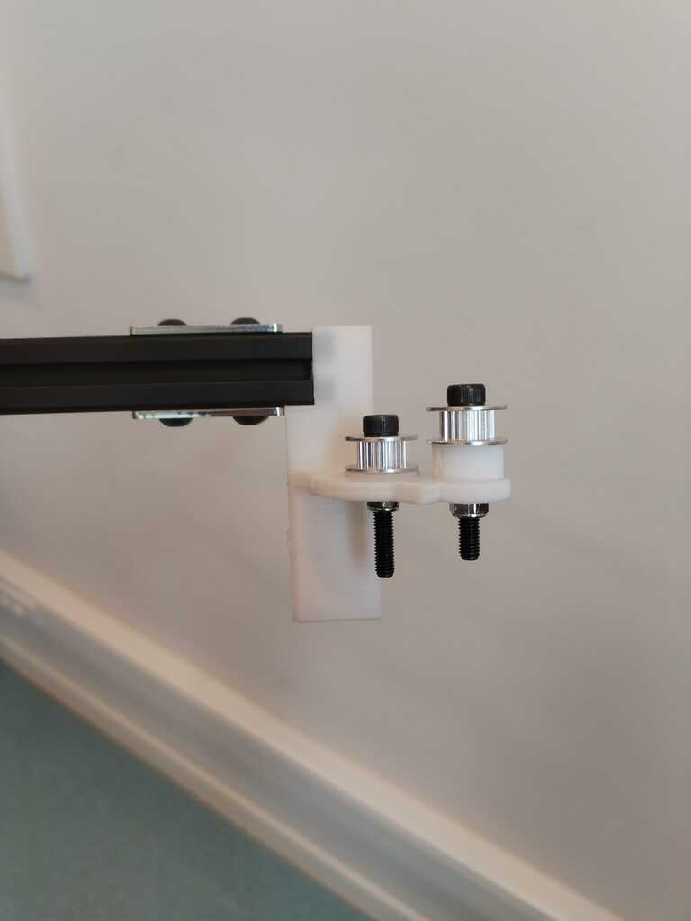
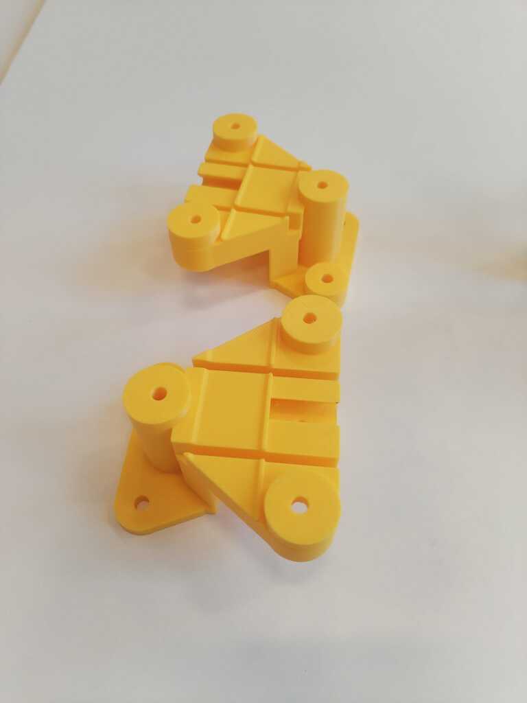
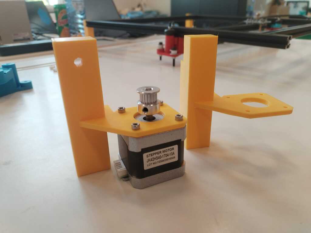
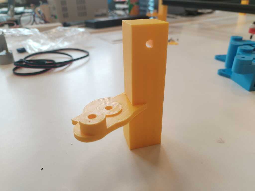
New feet were printed ! These are the two supporting the pulleys ...
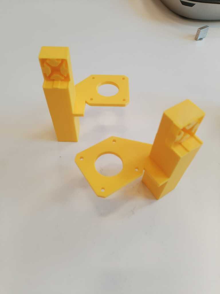
Note
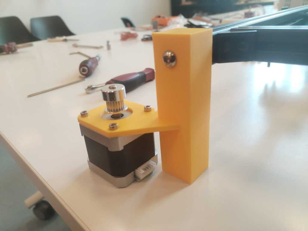
... and these are the two supporting the motors.
Note
The first slider prototypes were printed as well.
Note
We added wheels to the latter.
Note
And we tested if the extrusion bar was fitting.
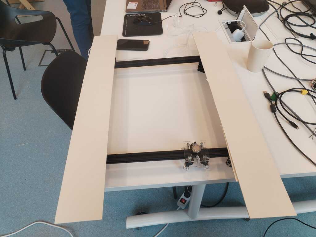
Structure Building 2<
Note
We could now start building the structure in order to perform a manual test.
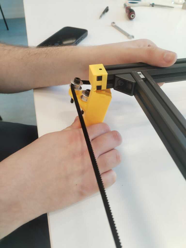
Note
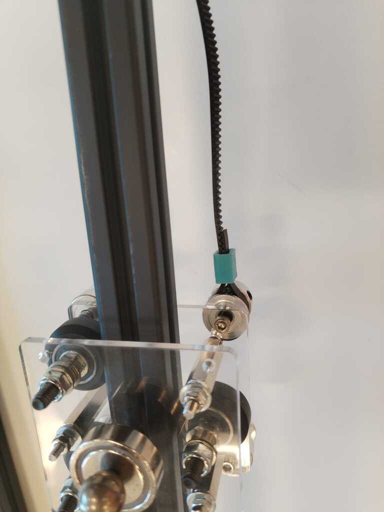
Therefore we attach a timing belt were it should be.
Note
And inserted it in the slider.
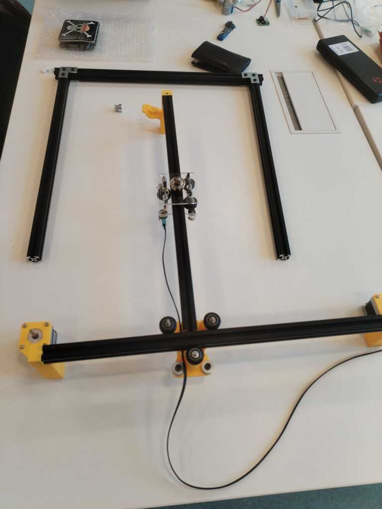
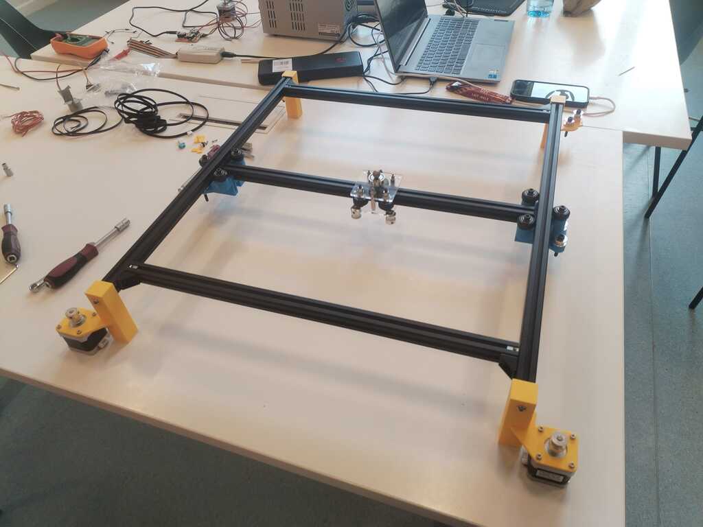
Note
The structure is starting to look fine !
Manual Testing Fail<
Note
We tried to perform a first manual test by pulling the belt and seeing if it moves correctly but one of the feet broke.
Note
Furthermore we realised the extrusion bar was not fitting well in the sliders. It was a bit twisted.
Sliders 2<
Note
New sliders were printed with a better gap between the wheels.
Note
We then built the moving axis with the new sliders.
Structure Building 3<
Note
The structure was rebuilt to verify if everything was good with the new sliders but it was not. The moving axis extrusion bar was touching the frame. It had to be modified again.
Feet and Sliders 3<
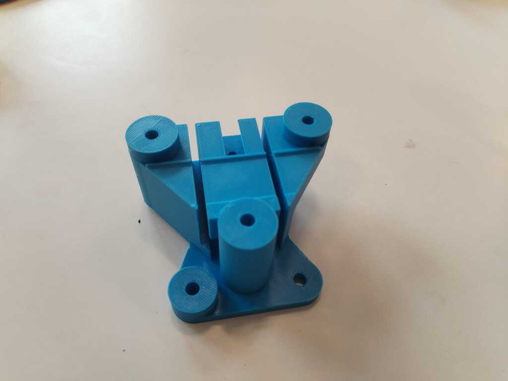
Note
More solid feet were printed.
Note
They can now be attached safely to the frame.
Note
New sliders were printed as well.
Note
We installed them and everything seemed fine.
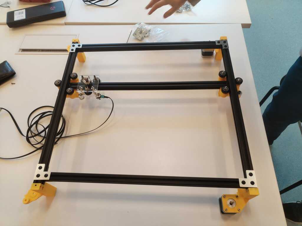
Structure Building 4<
Note
We then built everything together.
Note
And installed all the timing belts.
Manual Testing<
Note
We finally could perform a real manual test. It was working but the motion was not smooth at all and not it the good direction. Indeed pulling only one belt should induce a diagonal motion.
Note
We realised the belts were simply too tense so we adapted the tension a bit.
Note
Manual test was now quite good !
Sand Installation and Manual Test<
Note
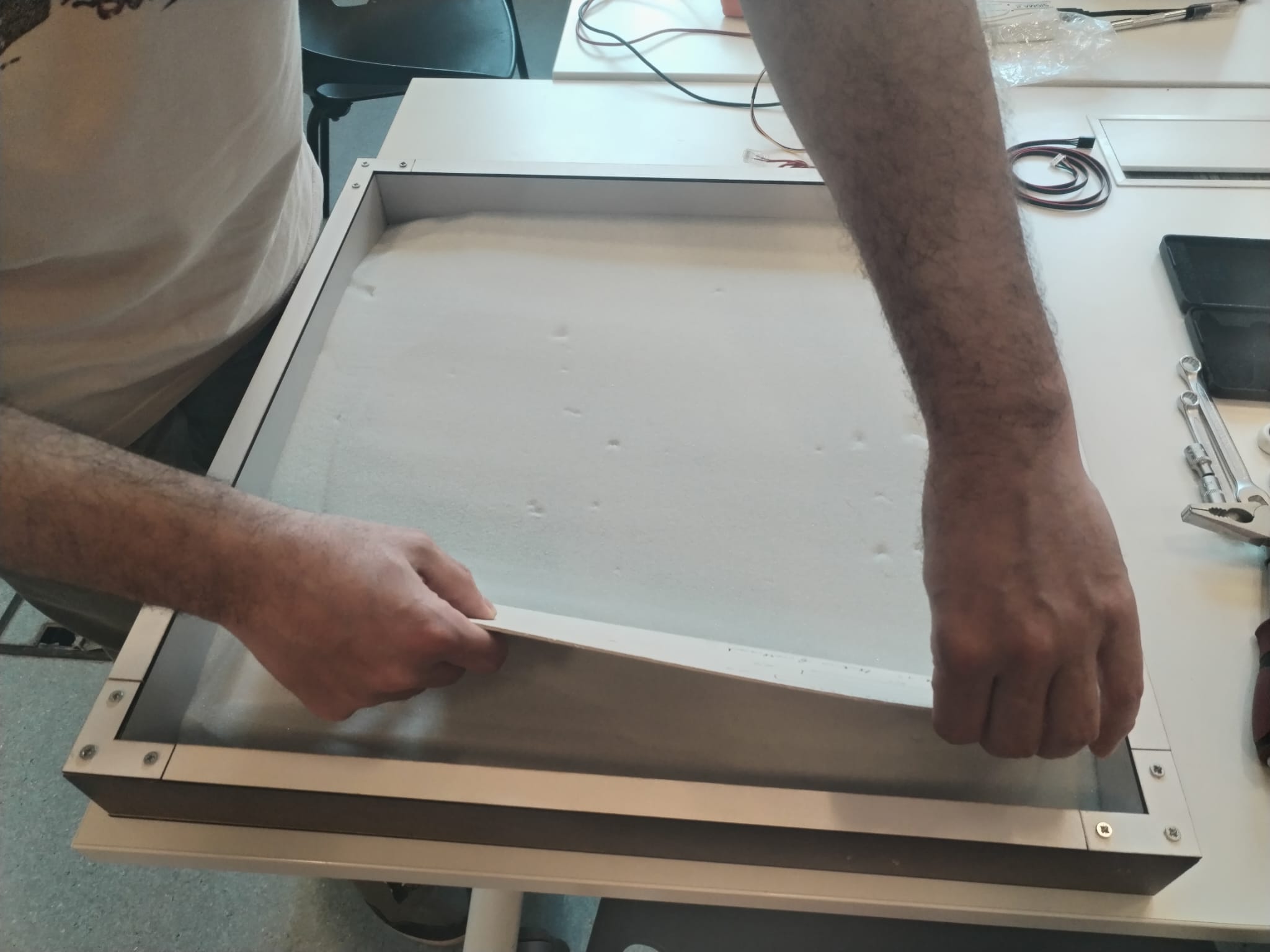
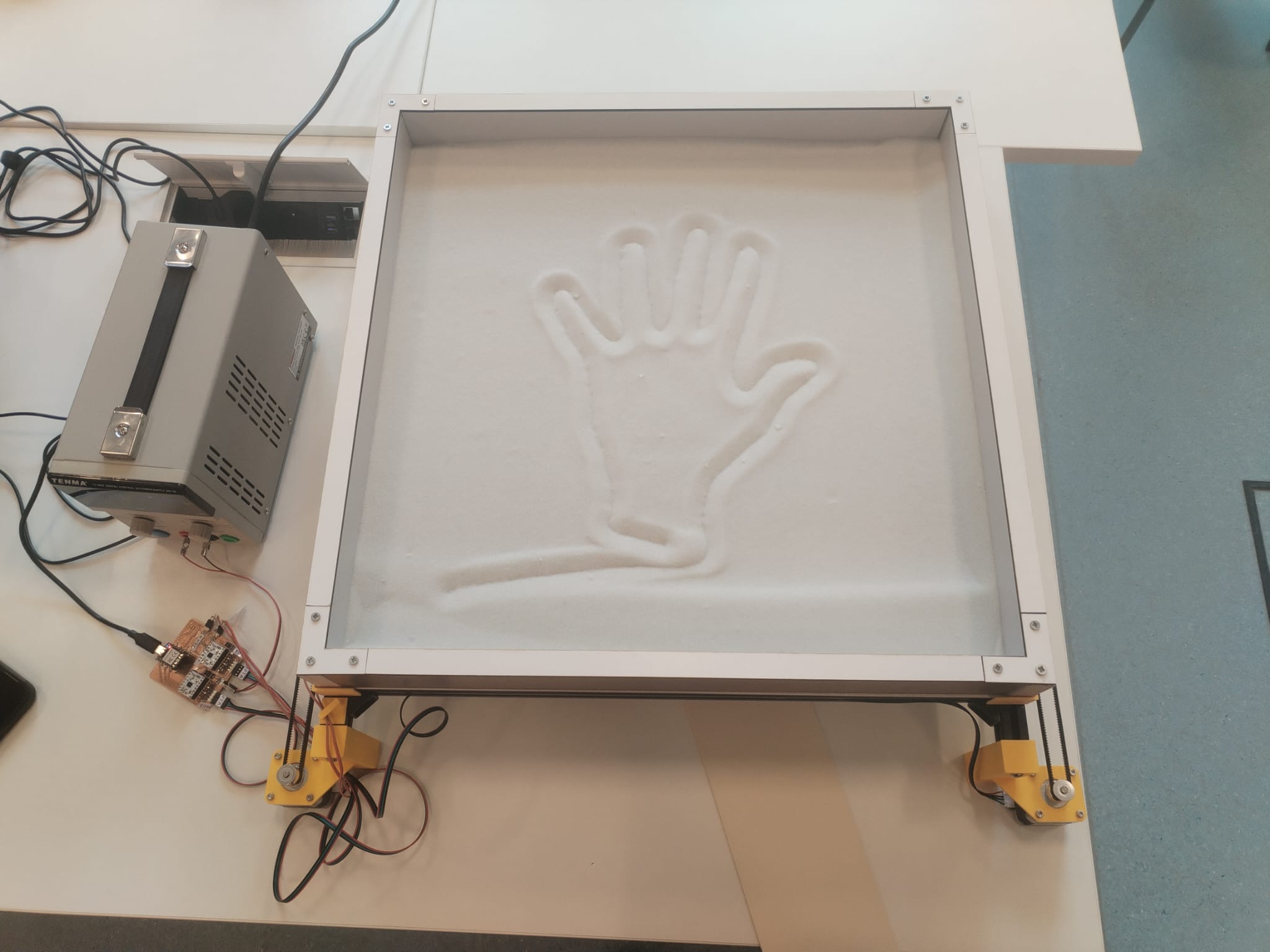
Finally ! It is the time to pour sand in our sandbox.
Note
Few things happened which I did not contribute to (home switch, sandbox support, electronics) but now we can finally put everything together. The marble was installed in the sand.
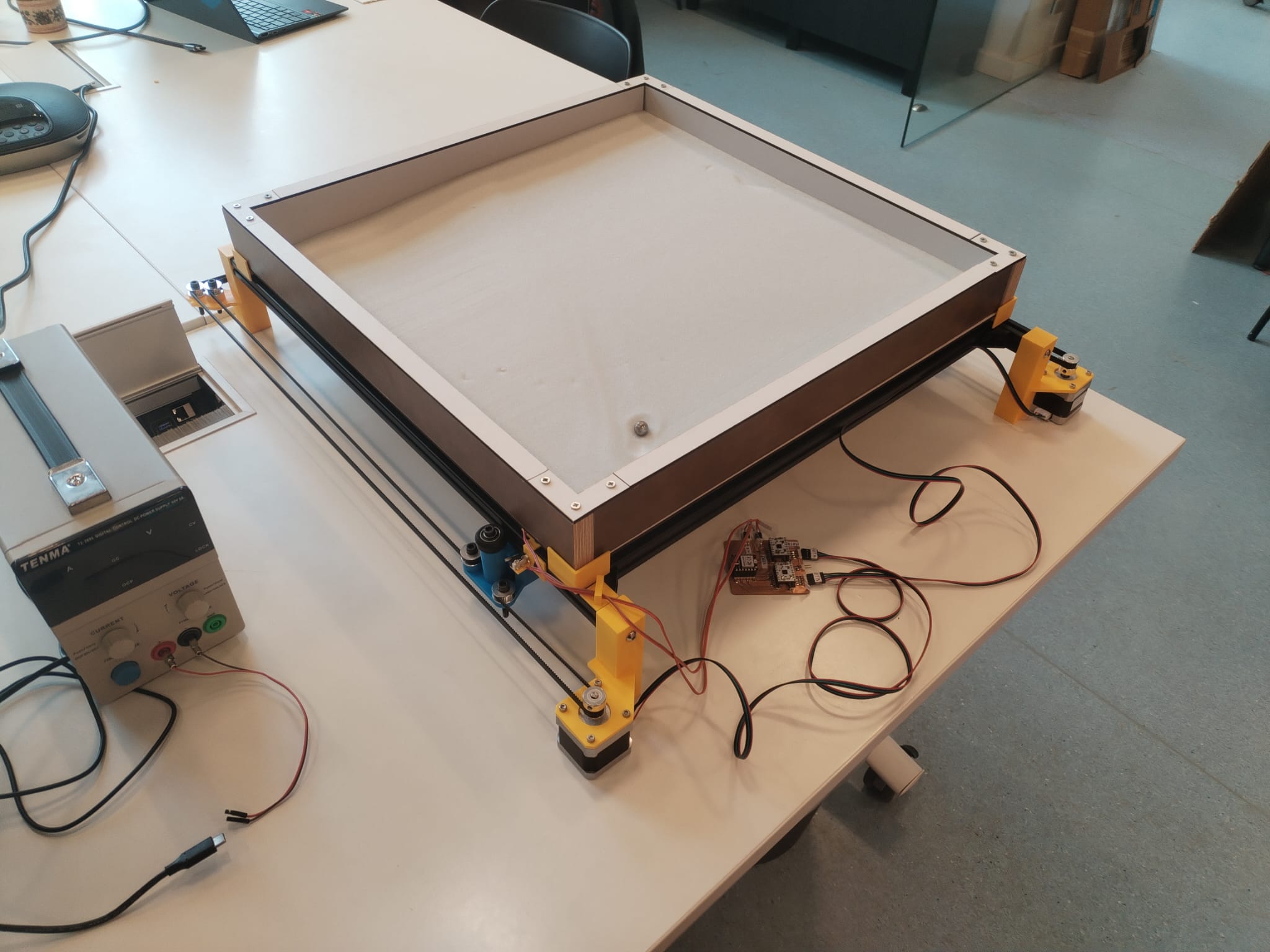
Automated Testing in Sand<
Further work is mainly electronics optimization which I did not contribute at all. Check the group page or Michel's page for more details however here are the first automated tests we made.
4.3. Presentation Video Editting<
My final contribution was to edit our presentation video. I shooted the video by using the "pause/play" button to avoid any cutting work. I then used KdenLive to add titles and credits.
5. Opportunities For Improvements<
According to me, the next steps to follow in order to imorove our machine are the following ones :
-
Software :
- Develop a more general G-code interpreter to allow curved motions
- Develop a user interface
-
Structure :
- Design smaller belt fastener to make the work zone bigger (they are blocking the cart to go to close to the frame)
-
System Integration :
- Design and build a PCB package
- Hide the wires
- Design and build a packaging for the cart