Machine week
General description
Our machine is a Kinetic sand table. It's described on our group page: https://fabacademy.org/2026/labs/ulb/group-assignments/machine-week/
Tasks assignment
Here is how we assigned tasks to evreyone:
- Elodie: Global structure and 3D pieces design (motor holders, feet…)
- Jonas: Design of the trolley for the magnet and aluminum frame assembly
- Fabio: Enclosure for the sand and magnetic ball
- Michel: Stepper motors control and PCB design
Personal contribution
I was responsible for the electronics and the low level code.
We decided to use a RP2040 to control our sand table.
First step: check we have all electronic components in our fab lab
I found:
- 2 bipolar stepper motor
- 2 Pololu DRV8834 module, to drive them
- Several Xiao RP2040
Fabio has switches in his lab that we can use as end-switches
PCB requirements
I started by counting the needed pins, to know if a Xiao module will do.
The Pololu module has 3 inputs that must be set externally:
- DIR sets the rotation direction (clockwise or counter-clockwise)
- STEP: a rising edge on this pin tells the motor to take a step
- nSLEEP puts the driver in sleep mode. It's active low.
nSLEEP would be handy to save power when the table is idle.
It could be shared by both modules, as both motors must always be active together.
Needed pins:
- STEP and DIR for each driver: 4 pins
- nSLEEP, shared by both driver: 1 pin
- 1 end-switch on each axis, for homing procedure: 2 pins
Optional pins:
- M0 and M1 driver signals will allow us to choose the micro-stepping mode. They can be shared by both drivers: 2 pins
- Control for a WS2812 LED strip: 1 pin
That gives a total of 7 to 10 pins.
The Xiao RP2040 module has 11 GPIO pins => 👍️.
Motor connections verification
The stepper motor is bipolar and comes with its own cable that has a 4 pin header.
One simple question is "Does its pin order matches the driver module's one ?"
I wanted to be sure of the phase order for the motor.
I made a simple test to answer this question:
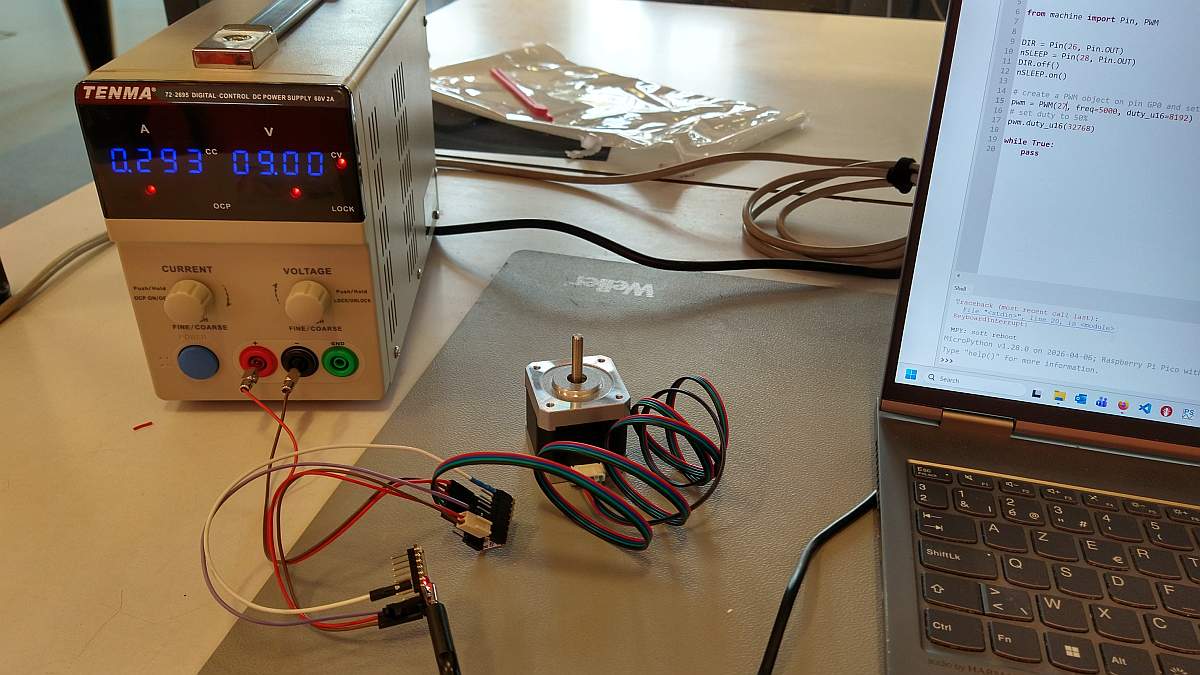
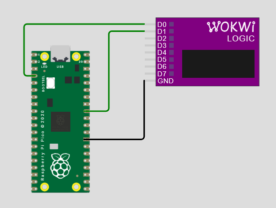
I started by connecting the Xiao, a stepper driver module and a stepper motor to check the connections:
- RP2040's P26 pin is connected to Pololu's DIR pin.
- RP2040's P28 pin is connected to Pololu's nSLEEP pin.
- RP2040's P27 pin is connected to Pololu's STEP pin.
- Stepper's pins are connected to Pololu's outputs.
I connected the motor pins in the "natural" order. By "natural", I mean that the tracks won't cross each other on the PCB.
Next, I wrote a simple test code in microPython:
- it sets DIR to 0
- it disables nSLEEP
- it outputs a 50% PWM signal on STEP
# machine week stepper connections test
from machine import Pin, PWM

# set P26 as output and its state to 0 (direction is not important for this test)
DIR = Pin(26, Pin.OUT)
DIR.off()
# set P28 as output and its state to 1 to activate the driver (nSLEEP is active low)
nSLEEP = Pin(28, Pin.OUT)
nSLEEP.on()
# create a PWM object on pin P27, set freq = 5 kHz and duty cycle = 50%
pwm = PWM(27, freq=5000, duty_u16=32768)

while True:
    pass
The motor should turn smoothly at constant speed.
If the motor doesn't move, there must be a problem in the signals generation.
If the movement is "jerky", it means that the phase order is not correct.
The test was successful.
That means that the PCB routing will be easier !
Schematics
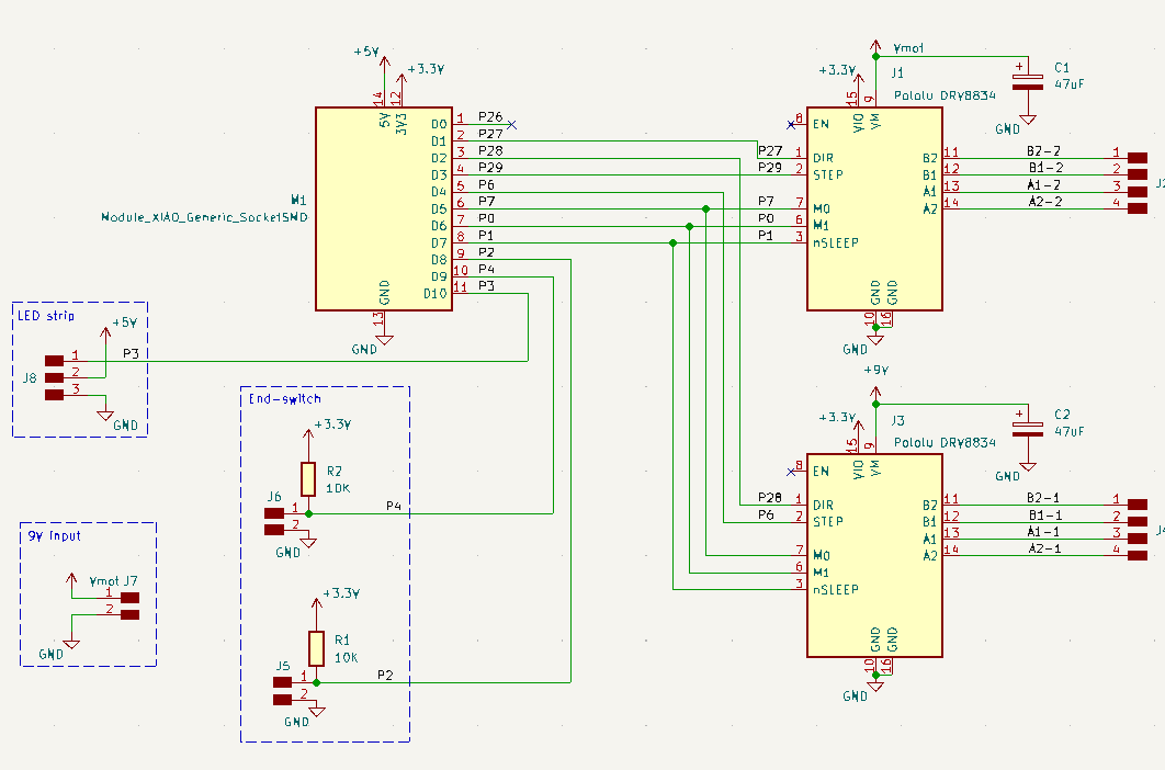
The PCB connects the Xiao module to the driver modules.
It has connectors for the end-switches and the NeoPixel.
There is another connector for an external power supply for the motor voltage.
PCB design
Routing
I routed the PCB:
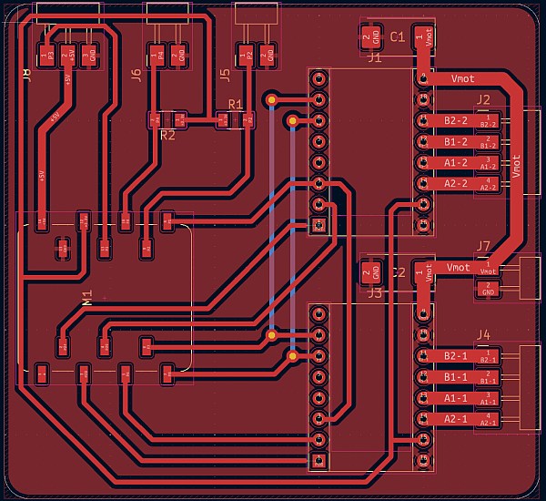
Fabio pointed out that the connectors for the driver modules were through-hole.
It means that they would be on the other side of the PCB, or that I would have to solder them on the top side.
We decided to change for SMD connectors.
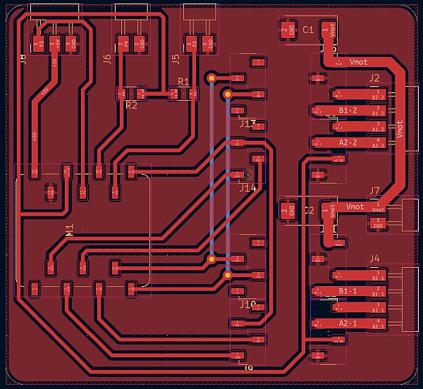
I would have to design a new footprint for the Pololu module.
To avoid that (and to save time), I added connectors to the schematics, connected "in parallel" with the modules.
Next, I imported them in the PCB, place them on top of the Pololu module and delete the modules:
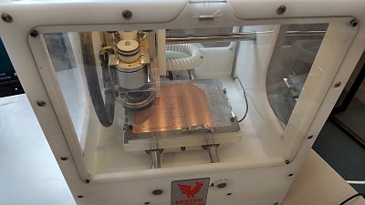
Production
Engraving went OK, thanks to the training from previous weeks.
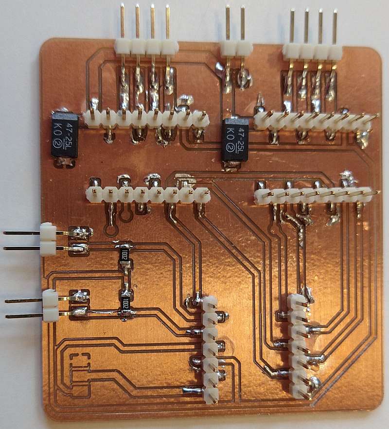
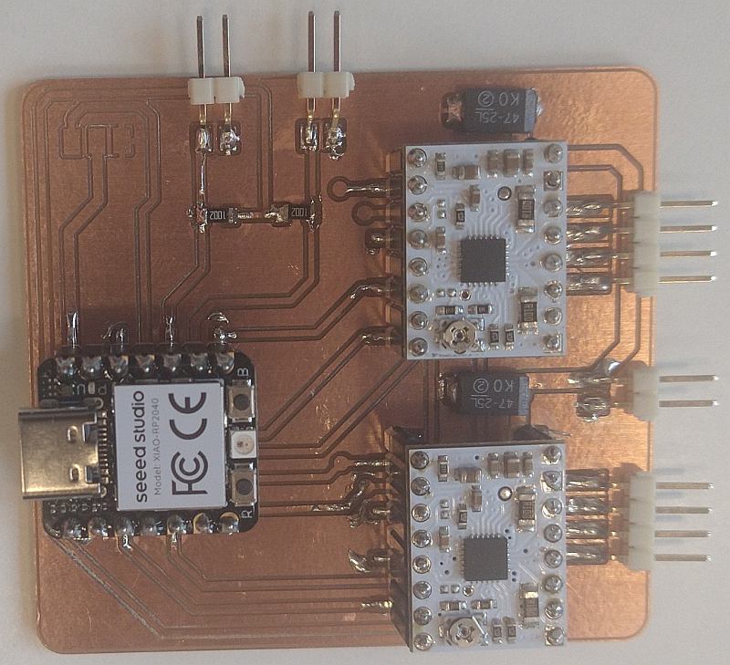
Next, I soldered the components:
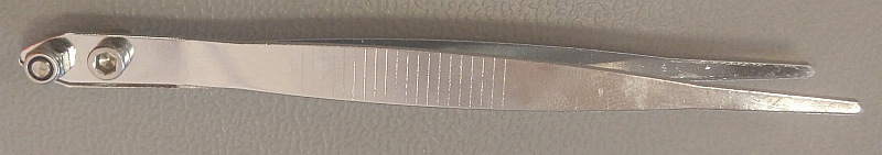
Only noticeable incident is that our tweezer broke and I had to repair it, with Patrik's help.
The solder point that connects both pieces broke. We replace it with 2 screws:
Testing
First, I checked for short-circuit between nets and found none.
Next, I connect our lab power supply to verify that the PCB doesn't draw too much current.
Test successful
Finally, I connected the Xiao module to my PC and upload a modified version of my stepper test code:
# machine week stepper test for PCB
import time
from machine import Pin, PWM

DIR0 = Pin(27, Pin.OUT)
DIR0.off()
DIR1 = Pin(28, Pin.OUT)
DIR1.off()
nSLEEP = Pin(2, Pin.OUT)
nSLEEP.on()
pwm0 = PWM(29, freq=500, duty_u16=0)
pwm1 = PWM(6, freq=500, duty_u16=0)

print("test motor A")
pwm0.duty_u16(32768)
time.sleep(1)
pwm0.duty_u16(0)

time.sleep(0.1)

print("test motor B")
pwm1.duty_u16(32768)
time.sleep(1)
pwm1.duty_u16(0)

nSLEEP.off()
print("done")
This program makes each motor turn for 1 second, one after the other.
Motor B did turn, but not motor A.
I did several tests to pinpoint the problem:
- I switched the stepper motors. It's always the motor identified as "motor A" by the Xiao that fails.
It means that the problem is on the PCB. - Next, I switched the driver module, to check if both were OK. They are.
- I remove the motor A driver and connected a logic analyzer to check the command signals generated by the RP2040.
They were as expected. - Finally, I reconnected the driver and used an oscilloscope to visualize the voltages on its pin.
I found that the supply voltage (9V) was missing.
It appears that I forgot to solder this pin.
After soldering it, both motors turn, but one quicker than the other.
I didn't solder the wires that connect M0 and M1 signal, because we don't plan to use it at first.
It means that only motor A driver has its M0 and M1 pins connected to the Xiao.
By default, M0 should be floating and M1 should be 0.
M1 is pulled down by the Pololu module.
I thought that the RP2040 pins will be floating by default, but I tried to set the Xiao's M0 pin as an input in the code.
It solved the problem.
Step signal generation
I started with a code to control a single stepper with a PIO's state machine.
It is based on the code I made during the Outputs week (that was designed for another driver).
Col
Col
This code drives one of the STEP outputs, with this sequence:
- line 7: wait to receive a 32-bit data from Tx FIFO. The lower 16 bits are the pulse duration. The upper 16 bits are the number of pulses to generate.
- line 8: copy the lower 16 bits in the ISR register. ISR'll save the step duration
- line 9: copy the upper 16 bits in the Y register. Y is the pulse counter
The code has 2 nested loops:
- "step" loop (lines 10-16) counts the number of pulses by decrementing Y.
- it sets the pin to 1, copy ISR in X. X is the duration counter
- it sets the pin to 0; The resulting pulse is short, but long enough to trigger the driver
- "counting" loop (line 14-15) is an empty loop, as its goal is to create a delay
- it sets the pin to 1, copy ISR in X. X is the duration counter
- it sets the pin to 0; The resulting pulse is short, but long enough to trigger the driver
In the main Python code, this snippet instantiates a PIO state machine with PIO code.
Here, it uses SM0, connects it to P27 pin and runs it at 10 kHz.
The second line enables the state machine.
| Stepper control | |
|---|---|
Col
Col
This code configures the DMA channel that feed data to the state machine.
Here, the first data (4) is the number of pulses and the second one (20) is the pulse duration, in state machine's period.
- lines 2-8 transforms the raw
data in a formatted bytearray, compatible with the DMA.
- line 11 creates the DMA channel
- lines 13-21 configures the data transfer
- line 23 starts the DMA transfer
- lines 24-25: the code waits for the transfer to end
data in a formatted bytearray, compatible with the DMA.test results
I tested this code in the Wokwi simulator:
The logic analyzer shows the output pin chronogram:
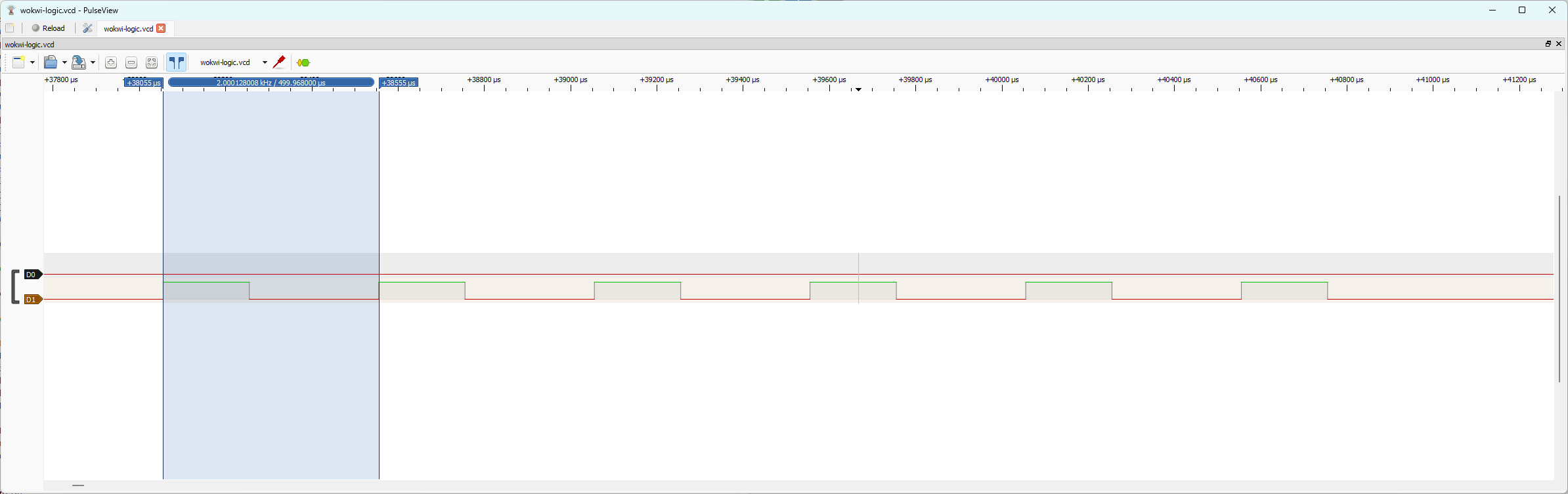
I tested it with different data:
| data | Pulse count | Period |
|---|---|---|
| [4, 20] | 5 | 2.5 ms |
| [4, 10] | 5 | 1.5 ms |
| [4, 0] | 5 | 0.5 ms |
These are the expected results:
- The "step" loop has 5 instructions (7 lines of code, but label are not an instruction). That's the minimum pulse duration.
- The "counting" loop has only one instruction
- The state machine's clock period is 100 µs (1/10 kHz)
Hence, step duration = (0.5 + X*0.1) ms = (5 + X) clock period.
There are one more pulses than the first data value, because the "step" loop counts down to zero included.
Code improvement
Next, I improve it by using the sideset capability of the PIO's instructions.
I also added some data encoding to ease sending 16-bit values in the DMA channel.
Controlling two steppers
Time to try controlling two steppers.
The code configures two state machines to execute the same code.
Each of them has its own DMA channel.
stepperInit() instantiates a PIO state machine to generate the STEP signal. It also configures a DMA channel to feed this state machine.
It returns this DMA channel's object.
stepperMoveConfig() takes the desired number of steps and their duration. It formats these data and stores them in the DMA channel.
This prepares both state machines for the desired moves, but it doesn't start the move.
The main code instantiates two state machines and configures a move for each of them. Then, it activates both DMA channels, back-to-back, so that they are as synchronized as possible.
It works, but there is a 120 µs delay between the output signals.
It can be caused by the execution time of the microPython program or by the clock speed of the state machines: a clock cycle is 100 µs.
Controlling the directions
I still have to generate the DIR signals. I didn't find an easy way to do it within the STEP generation code.
Hence, I decided to use a third state machine to generate them and to synchronize the STEP signals generation, using the PIO IRQs.
I added a new PIO code:
| start() | |
|---|---|
Its purpose is to generate the DIR signals for the steppers and to trigger the two other state machines.
As step(), it waits to receive a data from its Tx FIFO. This data is the state of the DIR pins.
The code sets the pins and activates two IRQs to trigger the other state machines.
Hence, I also had to modify step().
In fact, I had to duplicate it, as each state machine has its own IRQ.
Otherwise, I just had to had line20. It tells the state machine to wait for IRQ0 to be raised. Then, it resets the IRQ and resumes its execution.
I used this test code to configure the three state machines and execute two movements.
| test code | |
|---|---|
It works as intended.
The mechanical structure is also ready. Let's try to put everything together tomorrow!
Assembly test
Early morning problem
My code measures motors' movement in steps. We need to translate that in an actual distance.
First step (no pun intended), is to transform steps into turns. We know that
- motor has 200 steps/turn
- By default, pololu module are in 1/4 step mode => 1 turn = 800 steps
I add it with my motor test code, but the motor didn't turn.
I checked the PCB and found that the RP2040 was (very) hot.
I looked for short-circuit between all its pins (with a multimeter) and found none.
Then, I try to connect the Xiao alone to my computer, it became hot again.
The problem was with the Xiao. I soldered sockets on a new one and tried my code again.
It worked.
I don't know what caused the Xiao failure.
The test was conclusive: I asked 8000 steps and the motor pulley made 10 turns.
Mechanical debug
Fabio and I did some tests on the coreXY structure
The L-pieces could use some modifications:
- the 3 holes for the wheel screws are too small, we had to drill them up to 5 mm diameter
- a spacer has to be added between the wheel and the piece. it could be included in the L-piece
- The moving bar should be a bit smaller to avoid touching the structure
One of the feet broke. The walls of the pocket for the aluminium beam are too thin.
Elodie was homeworking today, we send her the modifications to make on the 3D models.
Fabio started to design pieces to attach the end-switches to the structure.
I continue writing the Python code.
New code features
The actual code misses several features:
- the main code can start a movement, but has no way to know when it finished
- nSLEEP, M0 and M1 has to be controlled properly
- The end-switches must be implemented.
I'll start with the movement end detection.
End of movement detection
I decided to use PIO's IRQ again.
The step generation state machines will set an IRQ flag when their current sequence ended.
@rp2.asm_pio( sideset_init=(rp2.PIO.OUT_LOW) )
def step0():
    wrap_target()
    pull()                  # pull a value from the RX-FIFO (fed by the DMA) to OSR
    out(isr, 16)            # copy the OSR's 16 lsb to ISR (step duration)
    out(y, 16)              # copy the OSR's 16 msb to y (nb. of steps)
    wait(1, irq, 0)
    label("step")
    mov(x, isr).side(1)             # initialize the duration counter
    label("counting")
    jmp(x_dec, "counting").side(0)
    jmp(y_dec, "step")
    irq(2)
    wrap()
The start state machine will wait for these IRQ flags to be set before pushing a data in its Rx FIFO
@rp2.asm_pio( out_init=(rp2.PIO.OUT_LOW, rp2.PIO.OUT_LOW) )
def start():
    wrap_target()
    pull()         # pull a value from the RX-FIFO (fed by the DMA) to OSR
    out(pins, 32)
    irq(0)
    irq(1)
    wait(1, irq, 2)
    wait(1, irq, 3)
    set(isr,1)
    push()
    wrap()
I wrote a new function to check if there is a new data in the start state machine's FIFO to know if the movement has ended (Don't forget to read the data to empty the FIFO).
def isMoving(self):
    if self.sm2.rx_fifo() > 0:
        self.sm2.get()
        print("stopped")
        return False
    else:
        return True
The main code use this function to poll the end of movement.
stepperMoveConfig(d0, 5, 10)
stepperMoveConfig(d1, 5, 10)
smStart.put(0)
while isMoving():
    pass
stepperMoveConfig(d0, 5, 10)
stepperMoveConfig(d1, 5, 10)
smStart.put(2)
This first implementation didn't work properly: the code never exit the while loop.
After some tests, I found out that it works when I had a small delay in the while loop:
stepperMoveConfig(d0, 5, 10)
stepperMoveConfig(d1, 5, 10)
smStart.put(0)
while isMoving():
    time.sleep(0.01)
stepperMoveConfig(d0, 5, 10)
stepperMoveConfig(d1, 5, 10)
smStart.put(2)
It seems that checking the Rx FIFO continuously causes the problem.
I don't exactly understand why, but as long as I have a workaround...
We are now able to make the magnet move!!
End-switches
Fabio added the two end-switches to the mechanical structure while I wrote the code to use them.
First, I added two lines at the beginning of the main code to configure the pins connected to the end-switches:
Then, I wrote functions to read their status:
We connect the switches to the PCB to test them.
Y end-switch was detected as always pressed. I measured the input voltage and find 2.74V ??
After checking the connections and some confusing time, I realized that, on the Xiao, the pin order is P1, P2, P4 and P3. Hence, the Y end-switch is connected to P4 and not P3.
Code restructuration
As my code structure is now clear, it's time to clean it. I decided to restructure it as a class.
My goal is to have a "high level" object abstracting the main program from the hardware "low level" functions.
Block diagram
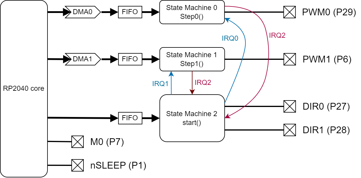
The main program runs on the RP2040 core. It controls directly the nSLEEP and M0 pins.
It controls the two stepper motors through three PIO state machines.
State machine 1 and 2 codes are based on the previous one: they receive data from a DMA channel and drives their output pin accordingly.
The main change is that they wait for an IRQ to be set before starting their sequence.
When the sequence ends, they sets another IRQ to signal it.
their code is explained in the next section.
State machine 2 runs the start() code (see below). The main program send it the direction of the motors.
It sets DIR0 and DIR1 accordingly an tells the other state machines to start their sequence by setting IRQs.
Steppers class
I put all the stepper related code in a class, to create an abstraction layer between the hardware and the main program.
The __init__() function instantiates the three state machines and configures the two DMA channels.
It also configures the other pins.
    def __init__(self, dir0Pin=27, step0Pin=29, step1Pin=6, endXPin=2, endYPin=4, M0Pin=7):
        # PIO init
        self.freq = 50000
        self.sm0 = rp2.StateMachine(0, step0, sideset_base=Pin(step0Pin), freq=self.freq)
        self.sm1 = rp2.StateMachine(1, step1, sideset_base=Pin(step1Pin), freq=self.freq)
        self.sm0.active(1)
        self.sm1.active(1)
        self.sm2 = rp2.StateMachine(2, start, out_base=Pin(dir0Pin), freq=10000000)
        self.sm2.active(1)
        # DMA init
        self.d0 = rp2.DMA()                     # creates the DMA channel
        c0 = self.d0.pack_ctrl( size = 2,       # Transfer 32-bit words
                          inc_write = False,    # don't increment the write address
                          treq_sel = 0 )        # transfer is initiated by the state machine
        self.d0.config( write = self.sm0,       # data destination is our state machine RX FIFO
                        ctrl = c0,
                        trigger = False )
        self.d1 = rp2.DMA()                     # creates the DMA channel
        c1 = self.d1.pack_ctrl( size = 2,       # Transfer 32-bit words
                          inc_write = False,    # don't increment the write address
                          treq_sel = 1 )        # transfer is initiated by the state machine
        self.d1.config( write = self.sm1,       # data destination is our state machine RX FIFO
                        ctrl = c1,
                        trigger = False )
        # end-switches pin init
        self.endX = Pin(endXPin, Pin.IN)
        self.endY = Pin(endYPin, Pin.IN)
        # Microstepping
        M0 = Pin(M0Pin, Pin.IN)
        M0.off()
The moveEncode() function is an utility function that formats the data for the DMA channels.
    def moveEncode(self, stepNb, stepDuration):
        stepDuration = stepDuration - 3
        if stepNb >= 0:
            stepNb = stepNb - 1
            data = bytearray( [ stepNb%256, stepNb//256, stepDuration%256, stepDuration//256 ] )
            dir = 0
        else:
            stepNb = -stepNb - 1
            data = bytearray( [ stepNb%256, stepNb//256, stepDuration%256, stepDuration//256 ] )
            dir = 1
        return dir, data
The moveStep() function receives the data for a movement (steps number and duration for both motors), configures the DMA channels and triggers the start state machine by sending it the motors' direction.
    def moveStep(self, stepNb0, stepDuration0, stepNb1, stepDuration1):
        dir0, data0 = self.moveEncode(stepNb0, stepDuration0)
        self.d0.config( read=data0, count=1, trigger=True )
        dir = dir0
        dir1, data1 = self.moveEncode(stepNb1, stepDuration1)
        self.d1.config( read=data1, count=1, trigger=True )
        dir = dir + 2*dir1
        self.sm2.put(dir)
The isMoving() function checks if the motors are moving or not. It allows the main code to know when the current movement ends.
    def isMoving(self):
        if self.sm2.rx_fifo() > 0:
            self.sm2.get()
            print("stopped")
            return False
        else:
            time.sleep(0.001)
            return True
XY movements
Next step is to control the motors based on XY coordinates instead of steps
Let's do the math
Our main source for the coreXY is https://corexy.com/theory.html.
We have:
$$ dA = dx + dy $$ $$ dB = dx - dy $$
where
- dA, dB are the distance of motor A and B
Here is the resulting function:
    def moveRelXY(self, dx, dy):
        dA = dx + dy
        dB = dx - dy
        l = sqrt(dx*dx + dy*dy)
        T = l / self.nomSpeed
        nA = int(dA * self.stepPerMeter)
        nB = int(dB * self.stepPerMeter)
        if nA != 0:
            tA = abs(int(self.freq*T/nA))
        else:
            tA = 0
        if nB !=0:
            tB = abs(int(self.freq*T/nB))
        else:
            tB = 0
        self.moveStep(nA, tA, nB, tB)
        time.sleep(T)
        self.x += dx
        self.y += dy
When I tested it, The problem with isMoving()happened again.
I made some research in the microPython documentation and RP2040 forums, but couldn't find an explanation for this bug.
I decided to avoid it by replacing it with a simple time.sleep() call.
As I can compute the movement duration (T), it's a totally acceptable solution.
With that bug fixed, we are now able to move the magnet with (dX, dY) commands.
Homing procedure
I added a new function to my class:
    def homing(self):
        while not self.endYPressed():
            self.moveStep(-10, self.slowPer, 10, self.slowPer)
            while self.isMoving():
                pass
        print("Y homed")
        self.moveStep(800, self.nomPer, -800, self.nomPer)
        while self.isMoving():
            pass
        while not self.endXPressed():
            self.moveStep(-10, self.slowPer, -10, self.slowPer)
            while self.isMoving():
                pass
        print("X homed")
        self.moveStep(800, self.nomPer, 800, self.nomPer)
        while self.isMoving():
            pass
It works at the first test!!
Absolute XY movements
The last missing functionality is to be able to move the magnet to an absolute (X,Y) position.
    def moveAbsXY(self, x, y):
        #print(f"Rel. move {x-self.x}, {y-self.y}")
        self.moveRelXY(x-self.x, y-self.y, self.nomSpeed)
        self.x = x
        self.y = y
It's simple to implement as it's just a matter to call moveRelXY()with the right parameters.
However, when we tested it, the magnet doesn't move as expected. Homing procedure went OK, but the following absolute movement was not right.
After some tests, we found out that, whatever move we ask, motor A doesn't move.
We were confused: it wasn't a hardware problem because homing was OK. After many tests, we decided to comment out the homing to save time. It solves the problem...
It appears quickly that it was the last move of homing() that causes the problem.
After some investigation, I realized that it's a 45° diagonal move. That means that one motor (motor A here) does not turn during this move.
step()function can't handle a zero step move. Indeed, it makes no sense.
In that case, the solution is not to send a command to the state machine controlling the motor that doesn't have to move.
    def moveRelXY(self, dx, dy, speed):
        dA = dx + dy
        dB = dx - dy
        l = sqrt(dx*dx + dy*dy)
        T = l / speed
        nA = int(dA * self.stepPerMm)
        nB = int(dB * self.stepPerMm)
        if nA != 0:
            tA = abs(int(self.freq*T/nA))
        else:
            nA = 1
            tA = 0
        if nB !=0:
            tB = abs(int(self.freq*T/nB))
        else:
            nB = 1
            tB = 0
        self.moveStep(nA, tA, nB, tB)
        time.sleep(T)
It solves the problem... allowing us to encounter the next one:
The five first magnet moves works well, but nothing happens afterwards.
This one was easy to spot: As I remove the isMoving() function in moveRelXY(), it doesn't read the data that start() state machine pushes in its Rx FIFO.
After five moves, the FIFO is full, blocking the state machine.
Hence, I removed the push() and modify homing() to use moveRelXY() (to get rid of homing()).
Interface with Fabio's application
Finally, I write a main code that receive commands from Fabio's application
if  __name__=="__main__":
    table = Steppers()
    nSLEEP = Pin(1, Pin.OUT)
    nSLEEP.on()
    table.homing()
    table.x = 0
    table.y = 0
    nSLEEP.off()
    print("Homed")
    while True:
        newX = int(input())
        newY = int(input())
        nSLEEP.on()
        table.moveAbsXY(newX, newY)
        nSLEEP.off()
        print("OK")
It's fairly simple:
tableis the object to control the steppersnSLEEPis deactivated to enable the motor drivers- We start by homing the sand table
- In the main loop, we wait for a (X,Y) coordinate, then move the magnet accordingly.
nSLEEP is activated between moves to avoid unneeded power consumption.
Further improvements
- Include a GCode decoding in the RP2040 code, to make the sand Table easier to interface with drawing applications (like sandify.org)
- Investigate why reading from the Rx FIFO in microPython doesn't work reliably