Global structure
Brainstorming
I discussed with Alexia about the most suitable structure for the sediment trap.
She already made a survey of the existing solutions (see here).
We quickly decided to use a single PMMA tube as sediment collector:
- the trap will be smaller and will have less pieces
- PMMA is transparent. That facilitates the underwater manipulation when retrieving it at the end of the experiment: the tube has to be filled with sand and sealed to prevent the sediment to move during the travel to the lab.
We also decided to use a disk dispenser as "intervalometer" (more on that on the disk dispenser page).
Conceptual sketches
Col

Col
The sediment trap can be divided in three parts:
- a funnel, in black. Its top is a grid. This grid's purpose is to create a calm space catching the sediments and allowing them to fall in the funnel.
- A sediment collector tube, in red. Its goal is obviously to collect the sediments. It must be removable and is contained in another tube which is the body of the trap.
- A disk dispenser, in blue. It will drop a disk in the sediment collector tube each month. These disks will serve as timestamp markers separating sediment layers.
Progress
- I modelled a first draft of the disk dispenser as part of the Computer-Aided Design assignments.
- After discussion with the biologists, it would be nice if the input grid could be made out of copper.
It would prevent marine organisms to fix themselves on the grid (a phenomenon known as biofouling).
I imagine making it out of interlocked combs, They will be laser-cut in a plastic material suitable with salted water.
Entry grid
I have 3 ideas to make the entry grid:
- use 2-sided PCB: it has a copper surface and is lighter and more rigid that a full copper piece
- use a copper-infused PLA filament to 3D print the grid in one piece. It will be easier to manufacture and assemble.
However, there is the question about the anti-fouling efficiency of this material. - use copper foil to cover the grid wall. The wall would be laser-cut in a plastic plate (material to be determined)
I will print a copper-PLA piece that will be placed next to the sediment trap during its first mission.
The idea is to test if it's fouling-proof, without risking the mission success.
global architecture
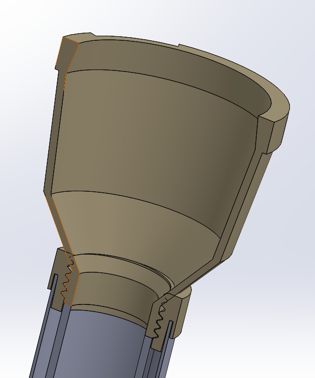
This is a view of the inside.
- At the top, there is the input funnel.
- The funnel is screwed in a adaptation piece. The trap should be easy to assemble and disassemble to allow transport by plane and samples retrieval under water.
- The adaptation piece is glued to a PVC pipe. This pipe will be the external body of the sediment trap.
- The sample tube will be put inside the PVC pipe. It will be a PMMA tube with a rubber cap at the bottom.
It will be hold in place between the bottom of the PVC tube and the bottom of the funnel. - The disk dispenser and the top part of the funnel needs to be added.
Electronics
Requirements
- Simple motor control: CW and CCW rotations, but no speed control.
- motor position sensor: we need to know how much turns the motor turns
- Real-time clock to count the number of days to wait between disk drops. No need for a "full" calendar.
- deep sleep mode: the system must works for one year on its battery. Each part must have a minimal quiescent current.
Motor choice
I considered two options: a DC motor or a stepper motor.
I choose DC motor for the following reasons:
- it's more compact. Space is a strong constraint in this project
- it's more efficient. It means less energy, hence smaller battery
On the other hand, it'll need a position sensor.
After some research, I found a compact motor with an integrated gearbox that suits my need.
Unfortunately, it miss a position sensor. I'll have to make one myself.
Motor control circuit
To minimize the quiescent current, the best choice is to make a H-bridge with discrete MOSFET transistors. PWM won't be needed as the motor will always be turning at full speed.
Real time clock
Two solutions:
- use an external RTCC that will wake the microcontroller up when needed
- use the internal microcontroller oscillator to implement a software RTC
As I don't need the real date and time, a RTCC is not mandatory.
From my experience, it leads to less efficient solution
I'll use the low power internal oscillator of the PIC, with an external 32.768 kHz oscillator.
Moreover, it allows to run the PIC at low frequency, decreasing its consumption.