Entry grid
The entry grid is here to guide the sediment in the trap.
It has to be a 1 cm square grid.
First prototype
A first prototype was built and installed before the fabacademy.
In this version, the entry grid is a single 3D-printed part, as it's easy to manufacture.
It's glued in the funnel.
I could have design both of them as a single piece, but I was anticipating that the disc dispenser has to be added.
The funnel is attached to the PVC tube with four screws.
Its installation teaches us several things:
- The fixation procedure was validated. I wasn't directly involved in this part of the project, but it was the main objctive of this first prototype
- 3D-printed ABS is not biofouling-proof: fouling appears on the funnel in a matter of days. We need an anti-fouling strategy
- The screw assembly between the funnel and the PVC tube is difficult to perform underwater.
Anti-fouling improvement
The classical anti-fouling method is to use anti-fouling paint.
The fact that the grid is part of the funnel makes it very difficult to paint. The anti-fouling paints are thick and the grid holes are small.
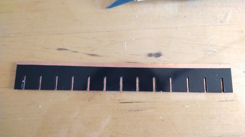
Hence, I designed the grid to be a press-fit assembly of laser-cut plastic sheets. The flat parts can be easily painted before assembly.
I selected HDPE plastic sheets, mainly because HDPE was often cited as a good choice for seawater resistant material.
Design
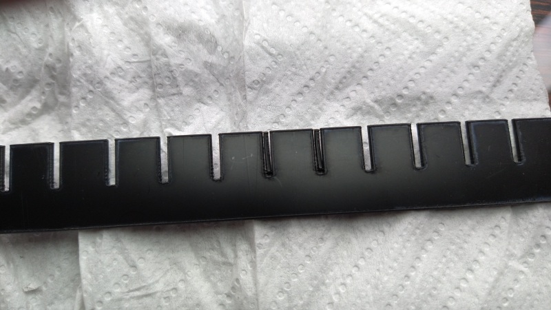
The grid holes are 1 cm squares. The wall thickness should as small as possible.
I seek for HDPE sheets for laser-cutting and found these.
They are available in thickness from 1 to 6 mm.
I chose the 1 mm sheets to have an acceptable thickness. Each part will probably be quite flexible, but once assembled together, the grid should be rigid.
Once I received the sheets, I measured their thickness and found values between 1.06 mm and 1.14 mm.
I painted a small piece with the anti-fouling paint to measure the added thickness and found a 0.15 mm increase.
I decided to add another 0.1 mm tolerance to design the "combs" that form the grid. This gives a slot width of 1.5 mm.
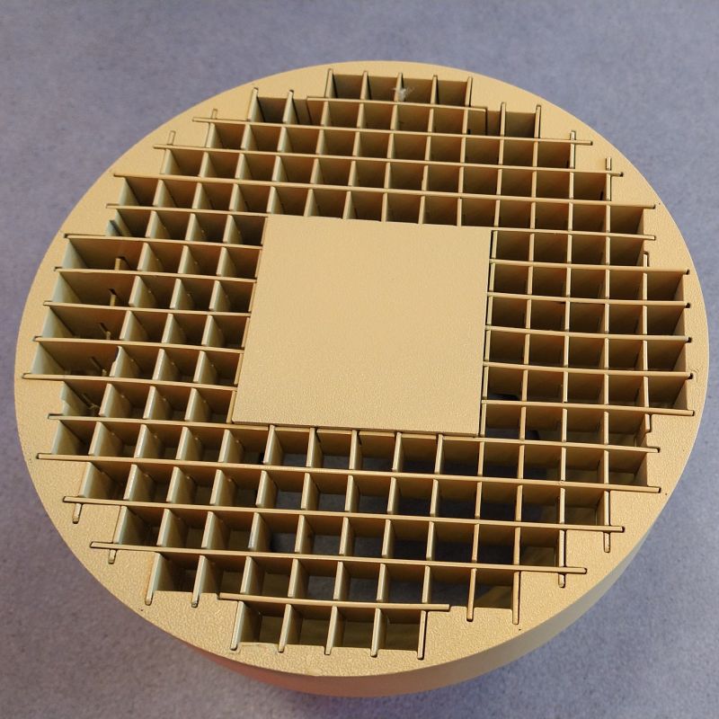
As the outer shape of the grid is a circle, I had to design multiple parts.
Moreover, as we wanted to minimize the trap's height, I let a hole in the middle of the grid for the disc dispenser.
Fabrication
I design all grid parts in solidworks, even if they are 2D parts, to be laser-cut.
Doing so allows me to include them in the 3D model of the trap and check if they fit correctly with the funnel.
I exported them as dxf files and import them in Deepnest.
I obtain a svg file combining all needed parts. I enabled the settings that shares edges between parts.
I cut it on the Lasersaur with a 100% power and 15 mm / min speed.
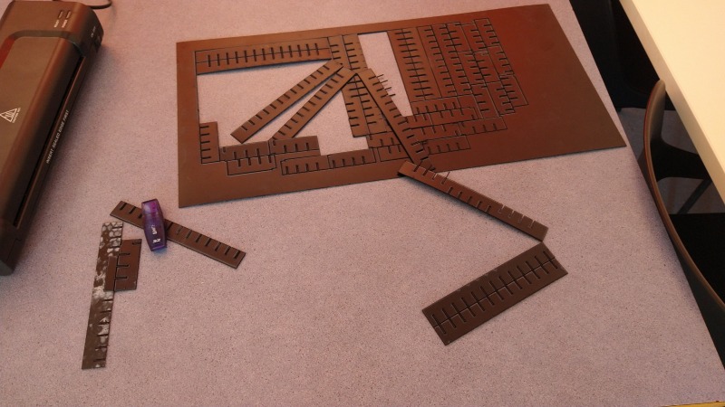
As shown of the picture, some parts sticks together by their corners. My hypothesis is that, when both edges of a corner are not cut consecutively, the laser melts some plastic and "glue" back the end of the other edge.
As I had to cut 3 grids, I cut the other one with a 2 mm gap between the parts and it solved the problem.
I still had one small default: small plastic "fingers" not completely cut, probably due to the the fact that they are very thin.
Anti -fouling finish
The grid's holes has to be completely free of obstacles for the sediment, hence, we need to prevent bio-fouling on it.
We decided to try two solutions to make the grid fouling-proof:
-
Paint all parts with an eco-friendly anti-fouling paint (we didn't want to pollute the coral reef).
-
Copper, which is a very powerful anti-fouling material. We first think of make the all grid in copper, but it will be costly and heavy.
Hence, we decided to use a copper foil on the grid's parts.
Painted version
Here is a picture of the painted grid, assembled with the funnel top. The anti-fouling paint is quite heavy, but the painting went well.
Copper-foiled version
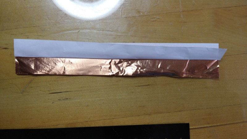
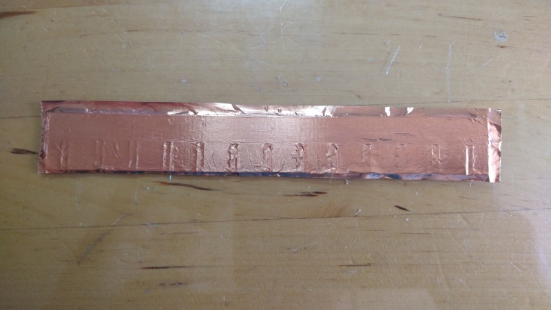
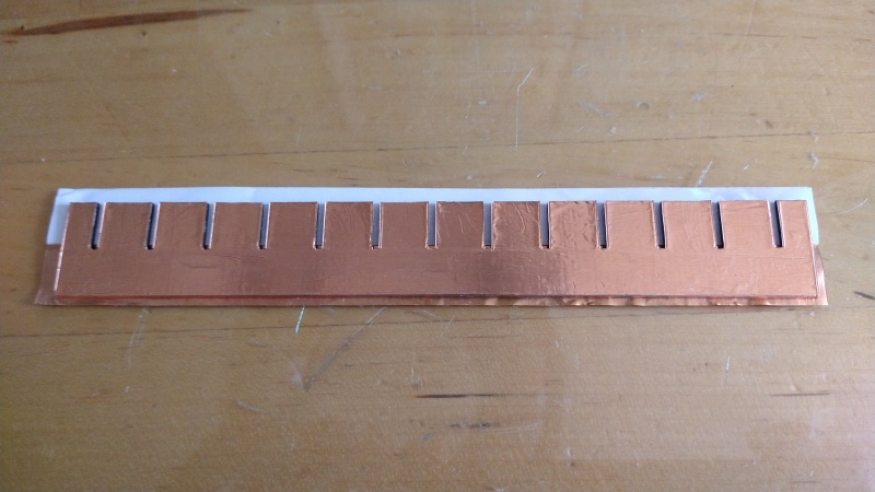
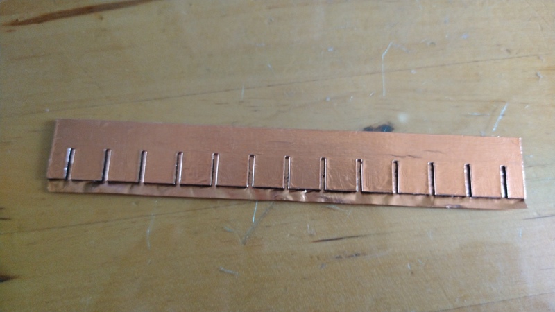
For the copper foil version, I used a 25 mm wide copper tape to cover both faces of each part.
Here is the procedure:
First, I peel half of the protective film. If I peel it completely, the copper foil easily folds on itself, and I had to throw it away.
I apply it with most of the copper excess at the top. That excess copper will be fold over the edge.
Press the copper on the part to make it stick. Use a piece of hard plastic (like a credit card).
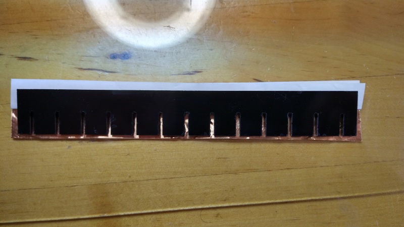
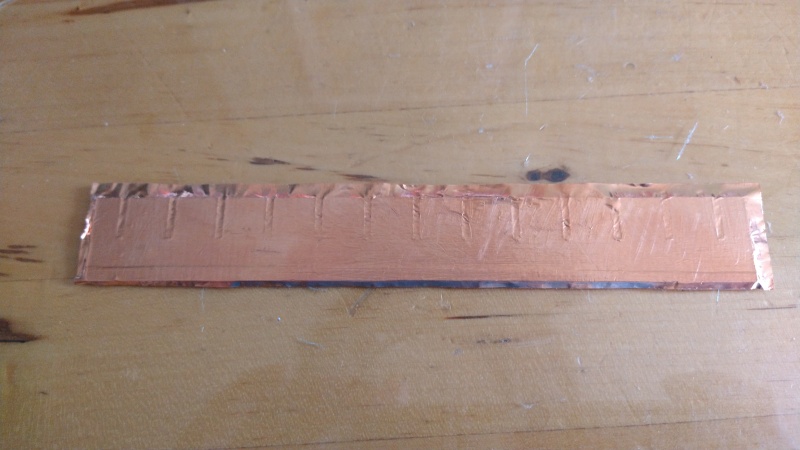
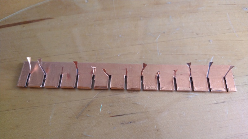
Cut the exceeding copper on both sides and at the piece. Fold the remaining copper at the top as shown here
Use a scalpel to cut the copper foil in the slots. Fold the copper "fingers" as shown.
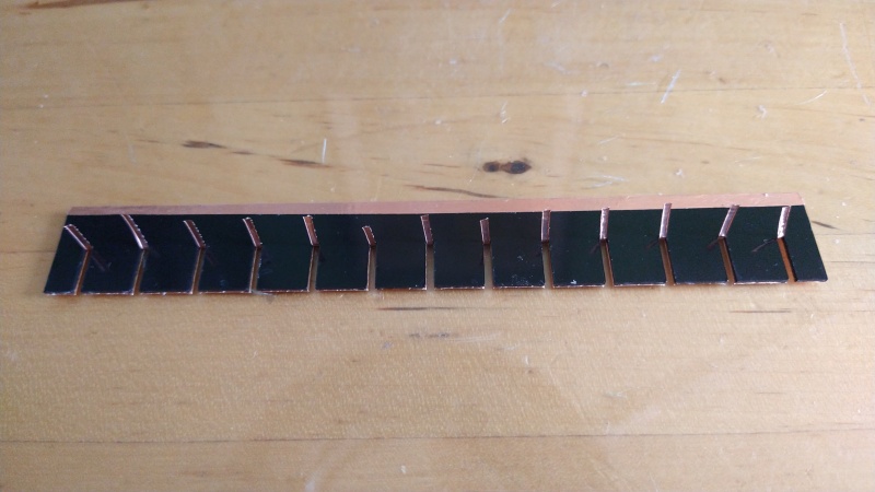
Use the scalpel to cut these fingers off.
Apply another copper sheet on the other face
Make it stick as for the first one
Return the part on the other side
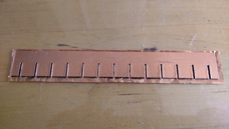
Cut the exceeding copper on the sides and at the top
Cut the copper along the slots, through the excess at the bottom and fold them up
Fold the remaining copper on the "teeth" of the piece
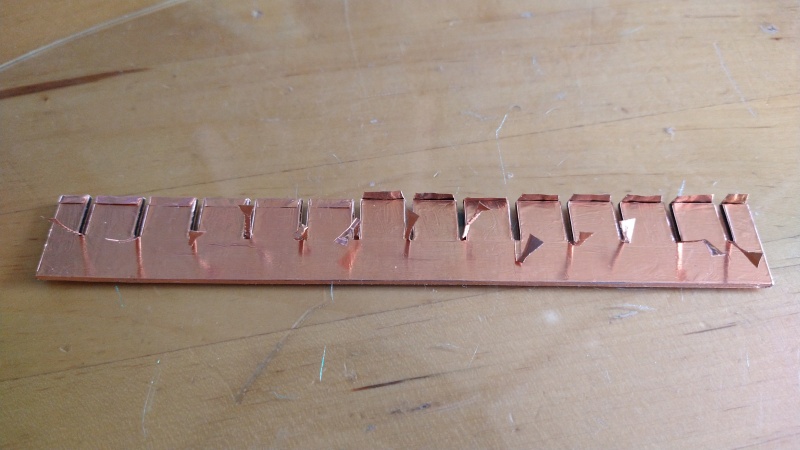
Cut the remaining fingers. Step 12 and 13 can be executed in any order.
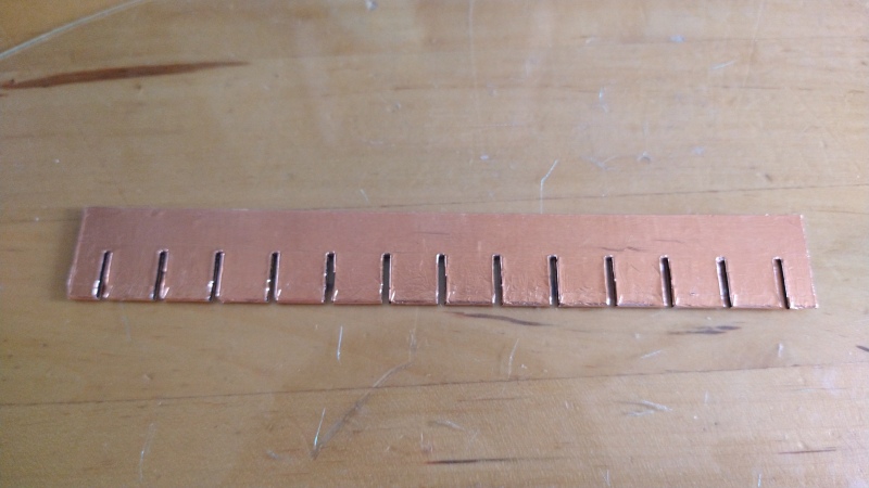
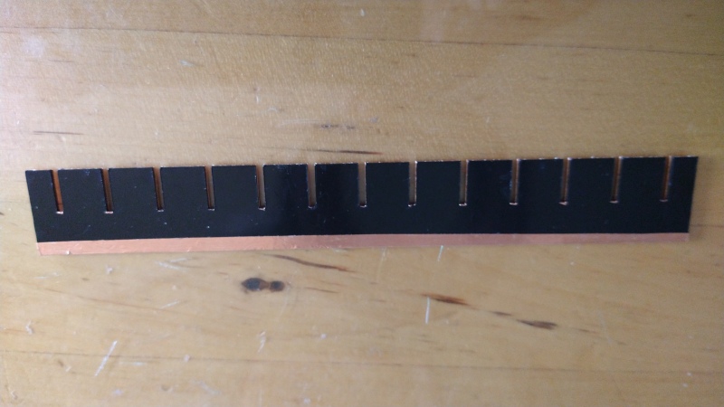
Here is the final result assembled.
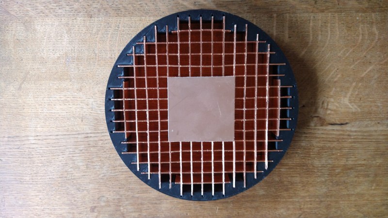
The black part is a test piece I printed to check if the grid can be assembled correctly. This part is the first 3 cm of the funnel top.
This way, if I made any mistake in the funnel design, I didn't hav to print the all part again (it takes almost 5 h).