
Final Project / Development
Development Log
The story of building NeuroAR across the weeks: from the first sketches and the EEG board to the wearable, the on-board SNN, and the dashboard, with a deep dive on each part.
Throughout this page, I document the progress of the NeuroAR throughout the weeks of Fab Academy. This page will have some information pulled directly from my weekly documentation alongside additional information on aspects of the project not documented in the weeks, which includes some documentation of spirals that didn't fit neatly inside the weeks :D
Use the toggle above to switch between a quick overview of each section and the full deep dive with the code and the debugging stories.
01: The Idea and the Initial Proposal
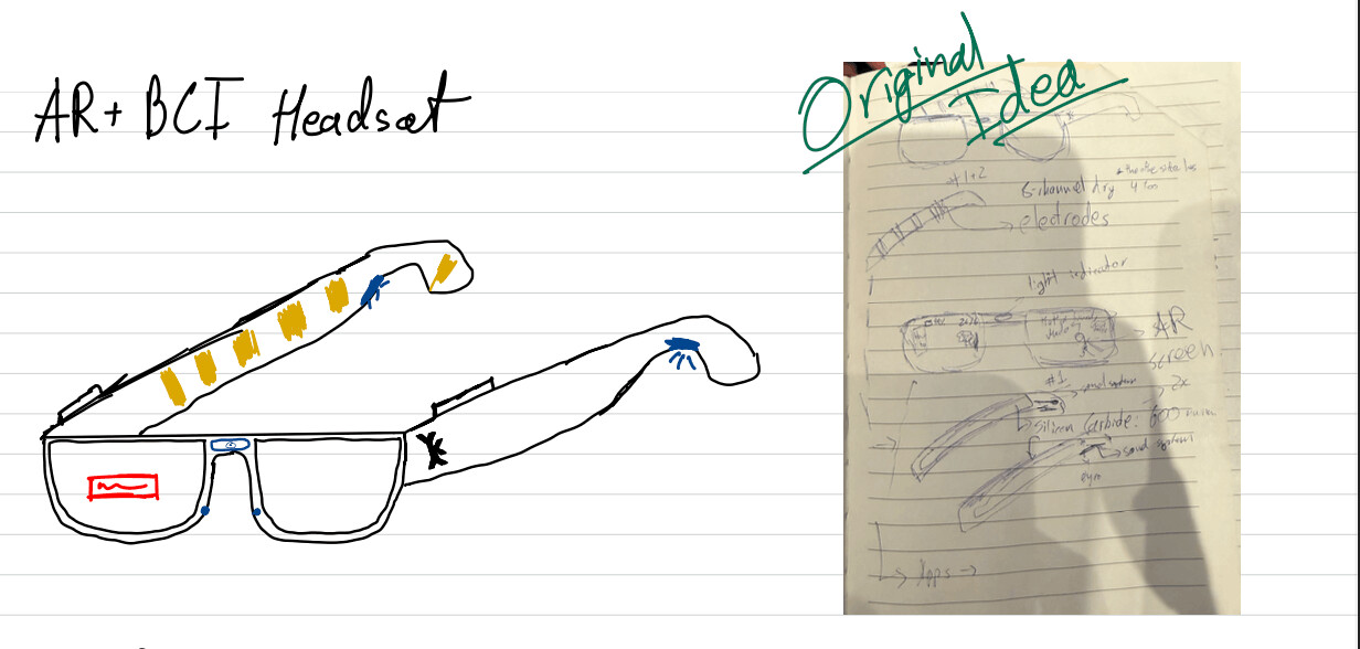
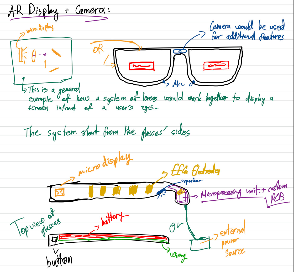
NeuroAR started as one of two project ideas in my initial proposal: a neuromorphic neuron visualization desk, and a wearable that combines EEG with augmented reality. I went with the glasses.
The idea is a wearable that measures biopotential signals from the forehead, processes the signal on a small MCU, and displays a minimal AR output through a micro-OLED mounted into the frame. You could view your AR display while tracking your brain activity without needing two separate wearables.
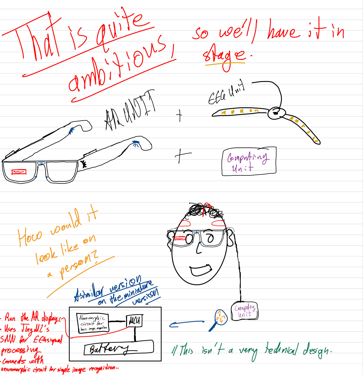
The proposal version of the plan assumed an ADS1299-based analog front-end with four electrodes, and a simple SNN classifier on an RP2040 or ESP32-S3. The real build ended up different in two honest ways.
First, the analog side simplified. I built and learned from analog neuron circuits early on, but the final project does not have a custom analog processing circuit. The sensing went through a dedicated biopotential chip (the ADS1292), and the brain-inspired part of the project lives in software as a LIF-SNN classifier instead of analog hardware.
Second, the scope spiraled. Instead of one big build, the project became a chain of spirals: a test board, a wearable, a software and SNN layer, and then connecting it to Poke through MCP. The final project page describes those spirals.
The proposal already admitted this stacks three hard things: reliable EEG sensing, wearable ergonomics, and optics integration. The plan to survive that was building each element separately first, then integrating. That is basically what happened.
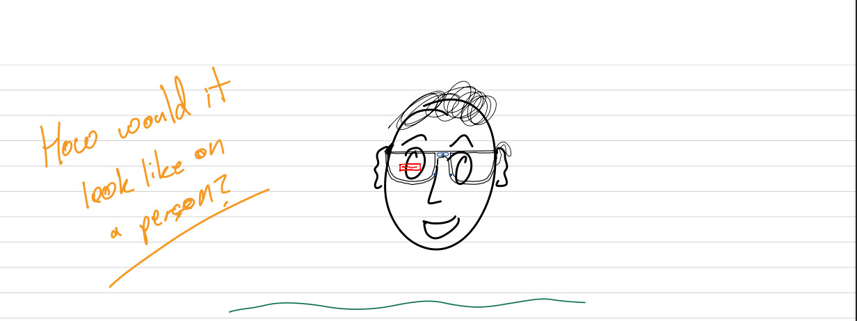
Here are the initial sketches from the proposal:
02: Frame, Identity, and the First Wearable Shape
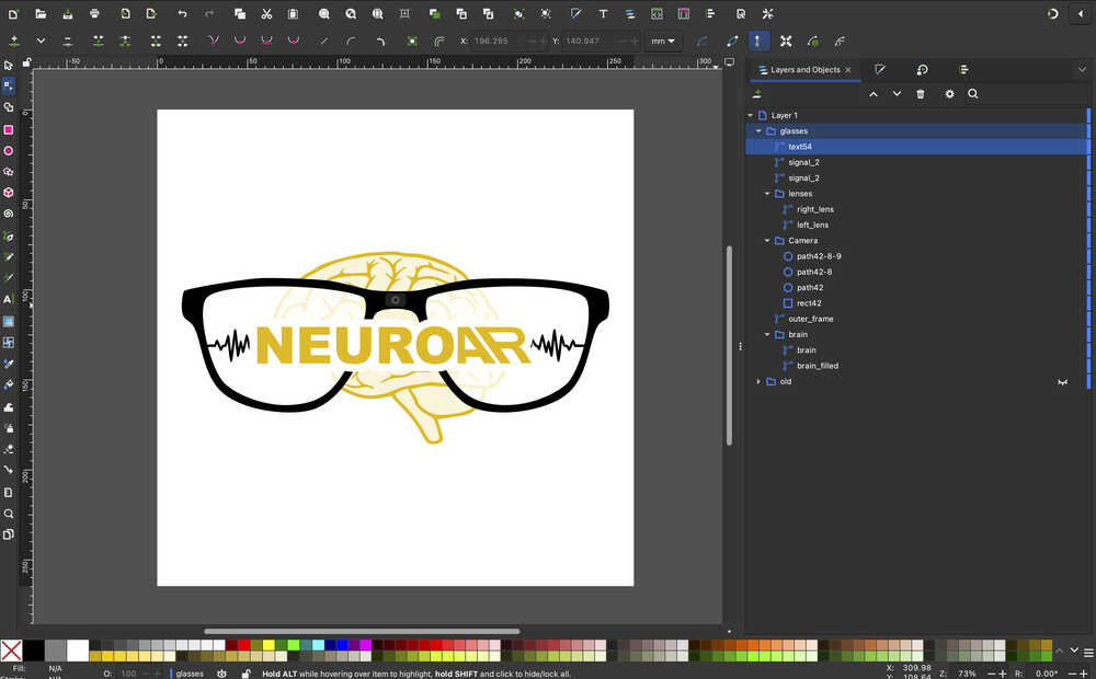
The first real thing I made for the project was the glasses identity and frame language. I designed the AR glasses + brain logo in Inkscape, then used it as a reference for the Fusion 360 frame model.
The point was not only making a logo. The logo became a way to think about the frame outline, the lens openings, and the way the object should look as a wearable. I set up the frame parametrically so the overall width and side proportions could be edited later instead of being a one-off sketch.
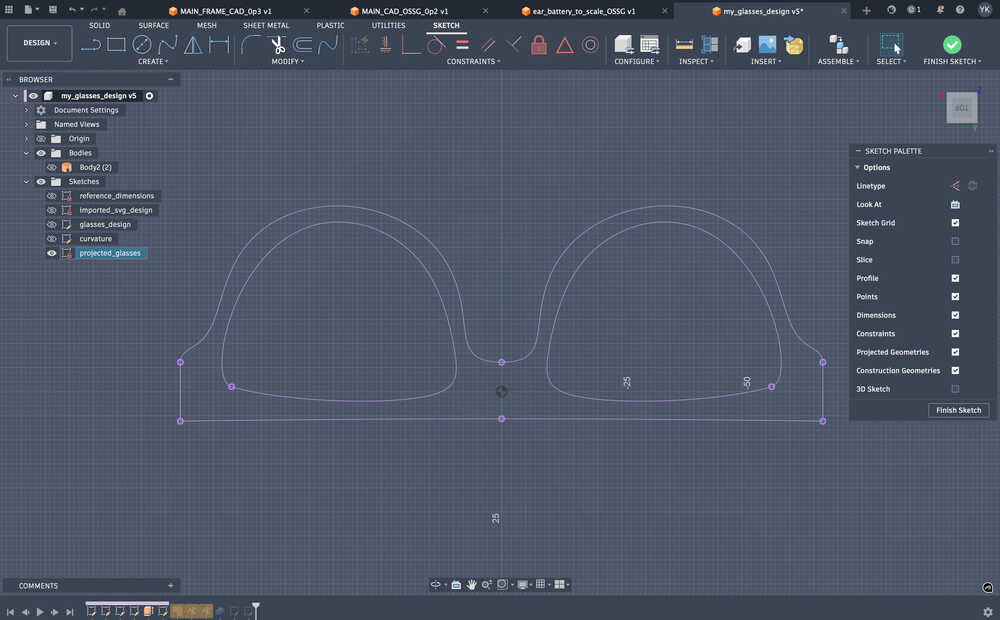
The harder CAD part was getting away from a flat drawing. I projected the frame onto a curved surface, patched the lens openings, and thickened the body so it started to behave like something that could sit on a face instead of something that only looked good from the front.
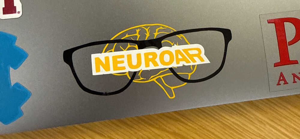
After that, I used vinyl cutting to make the logo physical. It was not a functional electronics step, but it forced me to work with layers, registration, transfer tape, and the same design files outside the screen.
03: Microcontroller Architecture and Early EEG Experiments
The first electronics spiral was not the custom board yet. I needed to know if the main pieces of the project were even reasonable on small hardware.
I chose the XIAO ESP32-S3 Sense because it gave me the combination I needed: BLE, camera interface, enough memory for small ML experiments, and a size that made sense for glasses. Then I tested the main subsystems separately.
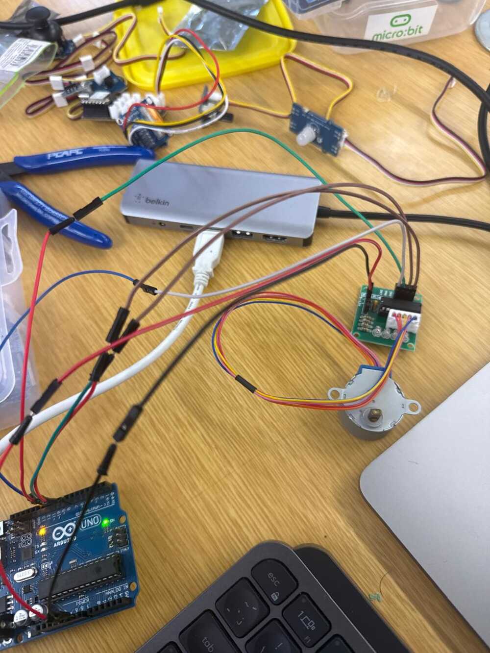
One experiment streamed Muse EEG into Python and sent blink events to an Arduino stepper motor. That was not the final architecture, but it proved that blink-like events could be detected and turned into physical output.
The more important experiment moved the EEG display path onto the XIAO. The XIAO connected to the Muse headband over BLE, decoded samples, applied filtering, calculated frequency-band values, and rendered a live waveform and blink counter on an OLED.
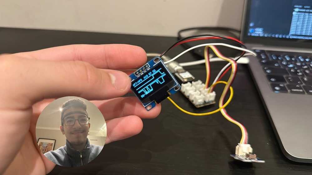
This gave me an early software pattern I kept coming back to: one side handles communication, one side handles the signal and display loop, and the UI should never pretend the data is cleaner than it is.
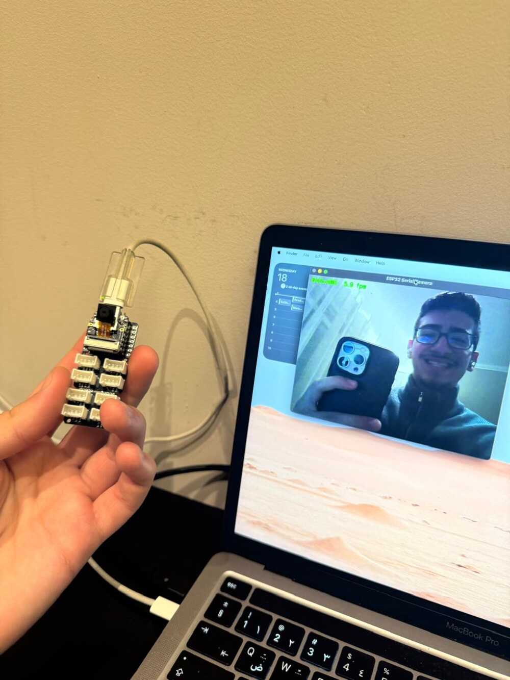
I also tested the OV2640 camera stream from the XIAO Sense. That was relevant because the final object was always leaning toward an assistant/XR wearable, not only a brain-signal board.
04: AR Display Mount and Optics Distance
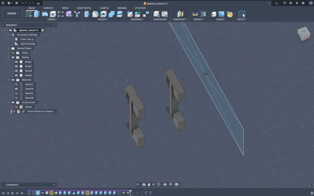
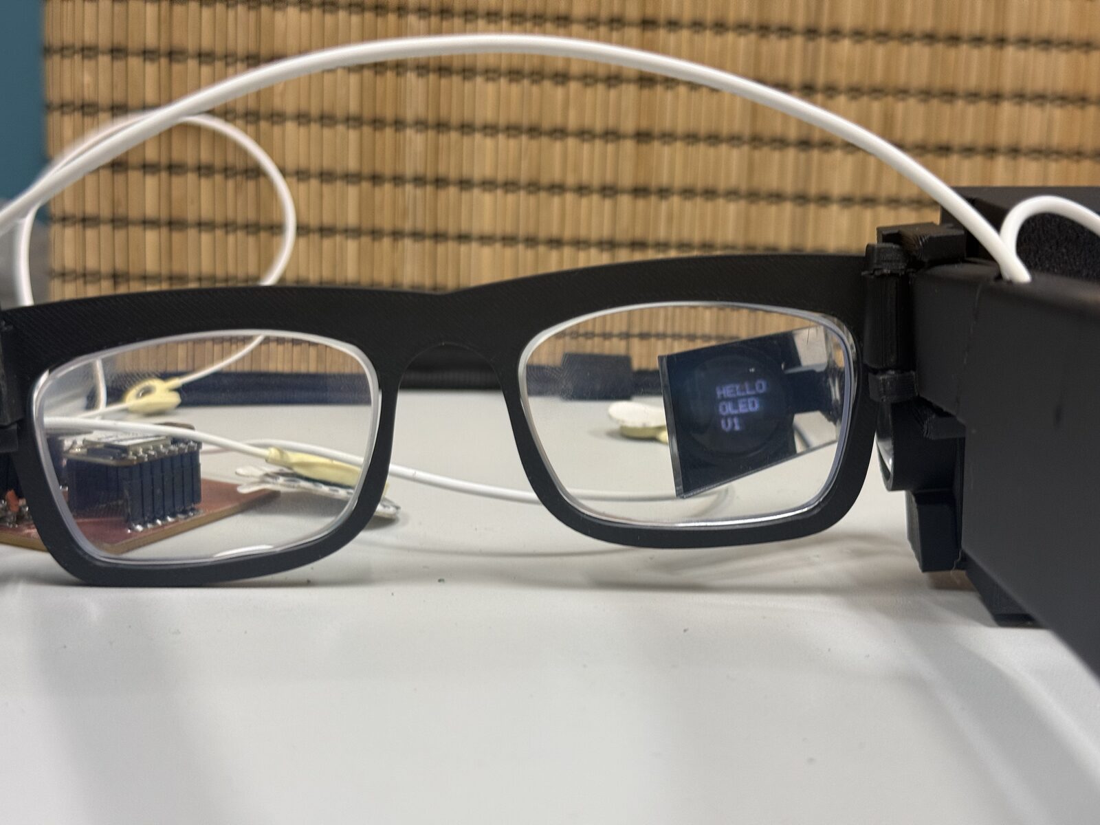
Once I had the first electronics path, I needed a way to physically hold the display on glasses. This became the first wearable mount: a 3D-printed hanger for the XIAO Grove Shield.
The display path immediately created an optics constraint. With only the screen and the refraction prism, the display could not sit right next to my eye and still be readable. The light needed distance before reaching the prism, so the first mount had to be longer and uglier than the future version.
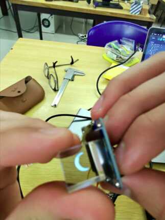
I measured my glasses, imported the Grove Shield model, and designed a bracket around the actual board instead of guessing. The first print failed because I did not chamfer the sliding edges, so I edited the design and printed it again.
This was the first move from "electronics on a desk" into "electronics attached to a wearable object." It was still a test rig, but it made the AR side feel less abstract.
05: Neuron Boards and My First PCBs
The LIF neuron board started as an electronics-design assignment. It was my first attempt to translate a neuron model into an actual circuit, with op-amps, comparators, RC timing, thresholds, and LEDs.
To be clear about where this landed: the analog neuron circuit did not end up in the final project. NeuroAR processes EEG with a LIF-SNN in software instead. But these boards are where I learned the electronics skills the project runs on.
The circuit was based on the idea of a leaky integrate-and-fire neuron. Instead of only simulating membrane voltage in code, I built the behavior from analog parts. The board also included a XIAO ESP32-S3 and OLED so the digital side could read and display the analog behavior.
The biggest thing I learned here was that "neuromorphic hardware" becomes extremely concrete very quickly. You stop talking about neurons as a concept and start dealing with virtual ground, comparator thresholds, power rails, ADC limits, and footprints.
The same LIF idea survived the move to software. The membrane-integration, leak, threshold, and reset behavior I wired by hand here is exactly the math the on-board SNN runs later in section 14.
Electronics production was where the neuron board stopped being only a KiCad file. I milled and stuffed my first PCB, which sounds simple, but it changed how I thought about every board after that.
Routing is one problem. Milling, soldering, trace width, pad size, tool choice, and repair are another problem. This week made the later ADS1292 board feel much less magical because I had already seen how easy it is for a board to fail from the physical side.
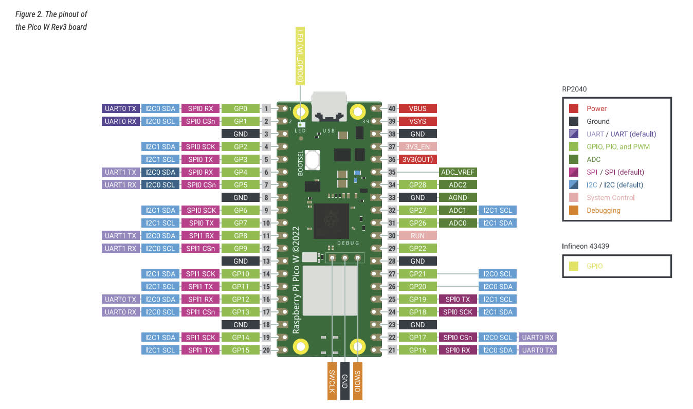
06: Multi-Board Communication and Wearable I/O
The networking week turned into two concept boards that later influenced the final system. One board used a Pico W with step-response pads and speaker output. The other used a XIAO ESP32-S3 with a SAMD11, display, button, and camera, and that one became the Spiral 0 EEG board in the next section.
For the assignment itself, the two boards became a networked music player. The XIAO was the controller with the OLED and button, and the Pico W played WAV files with the pads as a volume strip. I ran the same application over UART with jumper wires and over WiFi with HTTP.
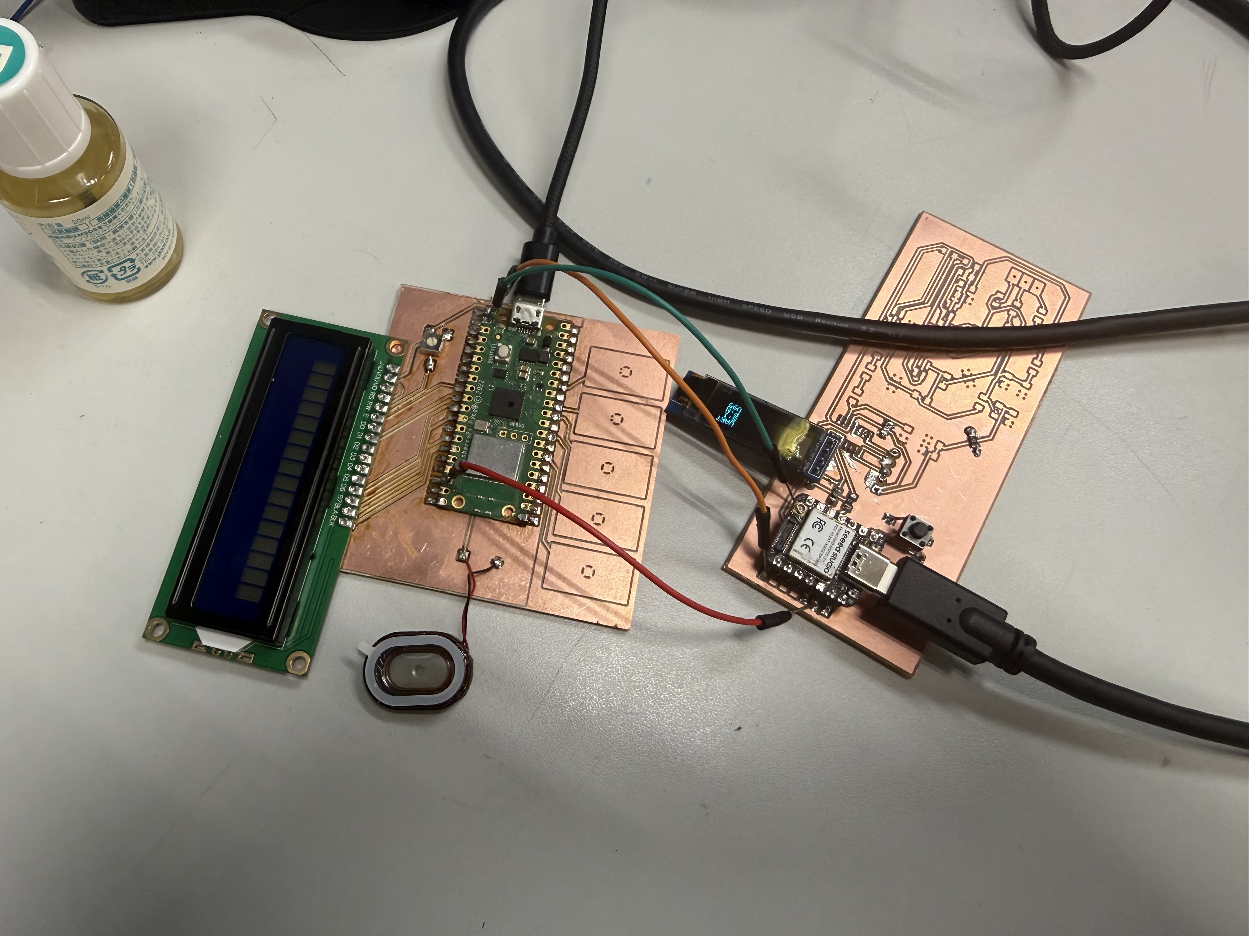
The useful part was not only that the boards talked. It was the structure: separate boards with different jobs, a simple message protocol, and enough debugging information to know which side failed.
The bug that taught me the most was a status race. The Pico sent periodic status packets, and right after a play command an old idle status could overwrite the "waiting" state on the XIAO. The fix was sequence numbers on every command and an acknowledgement field in every status packet:
PLAY,song,seq,name
STATUS,volume,state,song,statusSeq,ackSeq
A status packet is only allowed to override the waiting state if its ack matches the latest command sequence. Sequence numbers are cheap, and they tell you the difference between "the answer to my latest question" and "whatever the other side felt like saying just now." I kept that pattern for the rest of the project.
This is where the final project started to look like a distributed wearable instead of one magic PCB. Touch, sound, display, button input, camera, and a second microcontroller could all be separated if needed, then brought back together once the architecture was clearer.
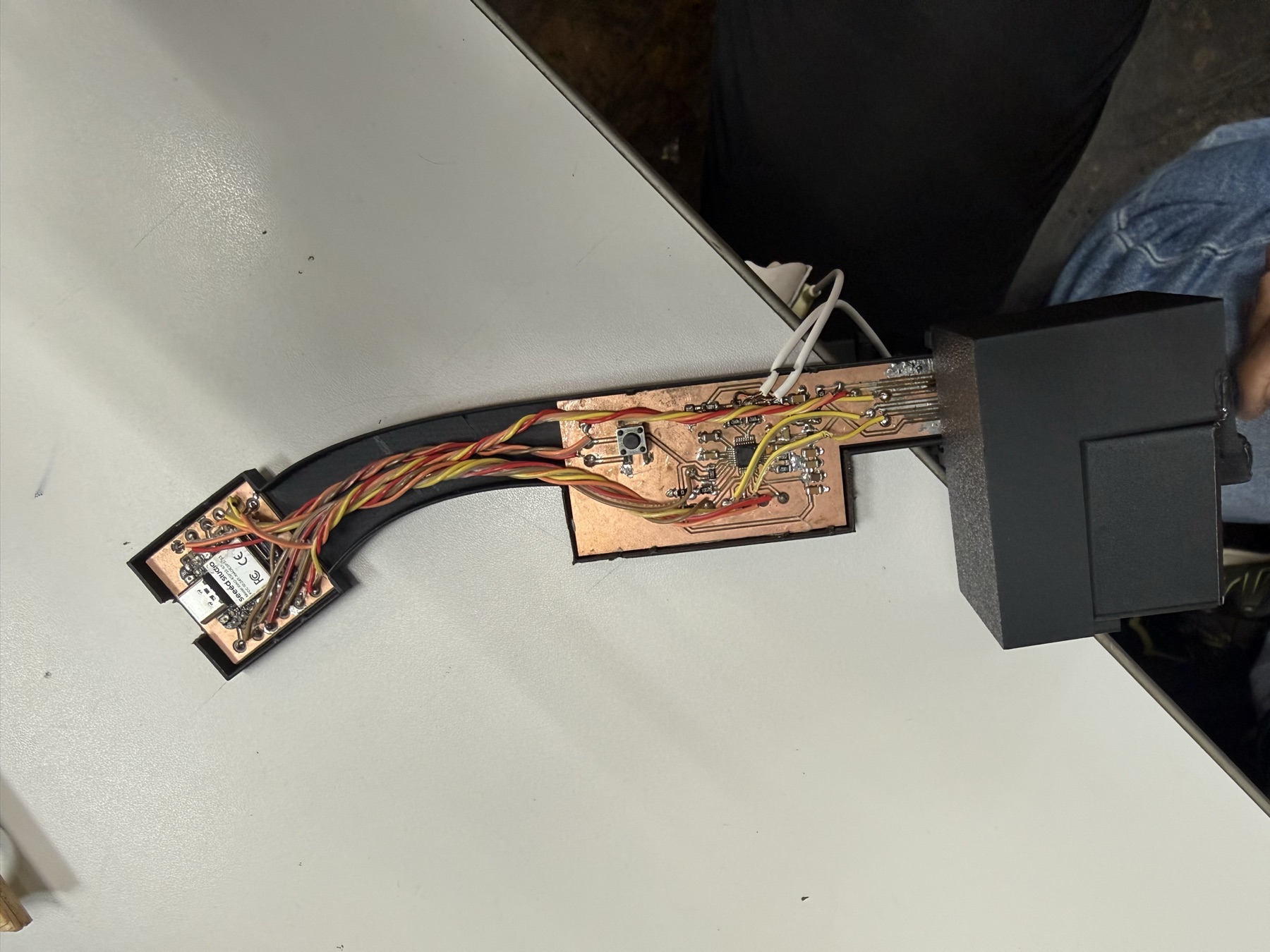
07: The Spiral 0 EEG Board
This is the board I mention in Week 11 but never fully documented there: the XIAO-camera-electrode-display board, my first custom EEG board and the heart of Spiral 0. One copper board with the XIAO ESP32-S3 Sense, an ATSAMD11C14A as a dedicated sampler chip, an OLED, a button, the camera, and a two-pin electrode header.
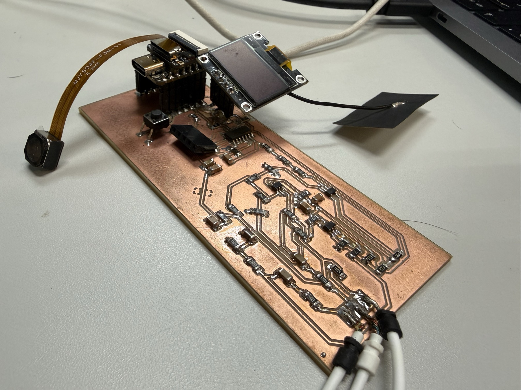
The architecture splits the work between the two chips. The SAMD11 does one job, sampling the electrodes at a steady rate, and the ESP32-S3 does everything else: filtering, display, camera, and WiFi.
The board itself
I designed the board in KiCad around the parts I already trusted from the earlier weeks. The BOM is small: the XIAO module, the SAMD11C14A in its SOIC-14 package, a 6 mm tactile button, a 4-pin I2C header for the OLED, a 2-pin socket for the electrodes, two 4.7k I2C pull-up resistors, a 10k and a 1k resistor, decoupling capacitors, and five test points for debugging.
The reason for a second microcontroller is timing. EEG sampling wants a fixed, steady rate, and the ESP32-S3 is busy serving WiFi, the camera, and the display. Giving the sampling its own chip means a WiFi hiccup can't skew the sample timing.
Flashing the SAMD11
The SAMD11 ships completely blank, no bootloader, no USB. The only way in is SWD, the ARM debug interface, and for that you need a programmer.
Instead of a dedicated programmer, I turned a XIAO SAMD21 into one. I built the Seeed CMSIS-DAP firmware in PlatformIO, got a uf2 file out of it, and dropped it onto the XIAO SAMD21 over its UF2 bootloader drive. After that, the XIAO presents itself to the computer as a CMSIS-DAP debug probe.
Then it is three wires plus power: SWDIO, SWCLK, and GND from the programmer XIAO to the SAMD11's SWD pads, with 3.3 V supplied to the target.
On the Arduino side, the Fab SAM core makes the SAMD11 a normal board target. The menu settings are what took me a while to get right:
Board                : Generic D11C14A
Serial Configuration : ONE_UART_ONE_WIRE_NO_SPI
Bootloader Size      : NO_BOOTLOADER
Programmer           : CMSIS-DAP
NO_BOOTLOADER means every upload goes through SWD, which is fine here because the board has the test points and the chip never needs to be reflashed in the field.
How I2C worked on this board
The serial configuration menu is also where I2C comes in, and this is the part that confused me at first. On SAM chips, peripherals like UART, SPI, and I2C are not fixed-function hardware on fixed pins. They are SERCOM blocks that get assigned a personality by the core you compile with.
ONE_UART_ONE_WIRE_NO_SPI tells the Fab SAM core to build a Wire (I2C) peripheral into the firmware. Pick a NO_WIRE option and the Wire library simply does not exist on the chip, and nothing on the bus will ever see the SAMD11. With a ONE_WIRE option, Wire lands on its default pins, PA14 for SDA and PA15 for SCL.
The bus itself has three devices: the ESP32-S3 as the controller, the SAMD11 as a peripheral at address 0x08, and the OLED at 0x3C. They share the same two wires, with the 4.7k pull-ups on the board, and the address sent at the start of each transaction decides who answers.
The SAMD11 firmware registers itself on the bus and answers read requests:
#define I2C_ADDR  0x08

void setup() {
    analogReadResolution(12);
    Wire.begin(I2C_ADDR);
    Wire.onRequest(onI2CRequest);
    setupTimer250Hz();
}
The sampling runs from a hardware timer, not the main loop. TC1 is fed from the 48 MHz clock with a /64 prescaler and a compare value of 2999, which works out to exactly 250 interrupts per second:
TC1->COUNT16.CTRLA.reg = TC_CTRLA_MODE_COUNT16 |
                         TC_CTRLA_WAVEGEN_MFRQ  |
                         TC_CTRLA_PRESCALER_DIV64;
TC1->COUNT16.CC[0].reg = 2999;          // 750 kHz / 250 Hz - 1
Every interrupt reads both electrode channels with the 12-bit ADC and raises a ready line, PA04, that runs to an interrupt pin on the ESP32-S3:
void TC1_Handler() {
    TC1->COUNT16.INTFLAG.reg = TC_INTFLAG_MC0;
    e1_raw = (uint16_t)analogRead(E1_PIN);
    e2_raw = (uint16_t)analogRead(E2_PIN);
    new_sample = true;
    digitalWrite(SAMD_RDY_PIN, HIGH);
}
When the ESP32-S3 sees the rising edge, it requests five bytes from address 0x08. The packet is deliberately tiny: one status byte, then both samples as big-endian 16-bit values.
void onI2CRequest() {
    uint8_t buf[5];
    if (new_sample) {
        buf[0] = 0xEE;                       // data valid
        buf[1] = (e1_raw >> 8) & 0xFF;
        buf[2] =  e1_raw       & 0xFF;
        buf[3] = (e2_raw >> 8) & 0xFF;
        buf[4] =  e2_raw       & 0xFF;
        new_sample = false;
        digitalWrite(SAMD_RDY_PIN, LOW);
    } else {
        buf[0] = 0x00;                       // no new data
        buf[1] = buf[2] = buf[3] = buf[4] = 0;
    }
    Wire.write(buf, 5);
}
The 0xEE status byte is doing the same job the sequence numbers did in the music player. If the ESP32-S3 reads 0x00, it knows it polled too early. If it reads anything other than 0xEE or 0x00, the read is misaligned and gets thrown away instead of being plotted as fake EEG.
Debugging the bus had its own mini toolkit. I wrote a diagnostic sketch for the SAMD11 that only brings up the I2C peripheral and returns a counter, so I could prove the bus worked before trusting the ADC side. On the ESP32-S3 project there is a second PlatformIO environment, i2c_scan, that walks all 127 addresses and prints who answers. When the scan showed 0x3C but not 0x08, the problem was the SAMD11 firmware. When it showed neither, the problem was wiring.
The ESP32-S3 side
The ESP32-S3 firmware polls the SAMD11 on the ready interrupt, with a 4 ms fallback timer in case an edge gets missed. Each accepted sample goes through five IIR band-pass biquads tuned for 250 Hz, one per EEG band, and a one-second running RMS window per band:
// 2nd-order Butterworth BPF @ Fs=250 Hz
const BiquadCoeffs kDelta = { 0.00463f, 0.0f, -0.00463f, -1.99048f, 0.99074f };
const BiquadCoeffs kTheta = { 0.01674f, 0.0f, -0.01674f, -1.96242f, 0.96651f };
const BiquadCoeffs kAlpha = { 0.02647f, 0.0f, -0.02647f, -1.92706f, 0.94706f };
const BiquadCoeffs kBeta  = { 0.07384f, 0.0f, -0.07384f, -1.73205f, 0.85231f };
const BiquadCoeffs kGamma = { 0.09500f, 0.0f, -0.09500f, -1.41421f, 0.81000f };
The OLED shows the result in three modes the button cycles through: a bar chart of the five bands, the numeric values, and the board's IP address. A long press dumps a camera JPEG over USB serial.
The same firmware runs a small web server, so the board was already a tiny networked wearable before the glasses existed:
http://<IP>/        landing page (camera + EEG)
http://<IP>/stream  MJPEG live camera stream
http://<IP>/eeg     EEG band power as JSON
The serial log also became the place where honest failure states live. The firmware distinguishes "SAMD11 not responding," "responding but no fresh samples," and "bad status byte," and prints a different message for each. That separation saved me real debugging time later.
What this board did not have yet is amplification. The electrodes fed the SAMD11's ADC through the passive input network, and EEG is microvolts. So the board read strong events and noise, not clean brainwaves. That problem is what Spiral 1's ADS1292 was for.
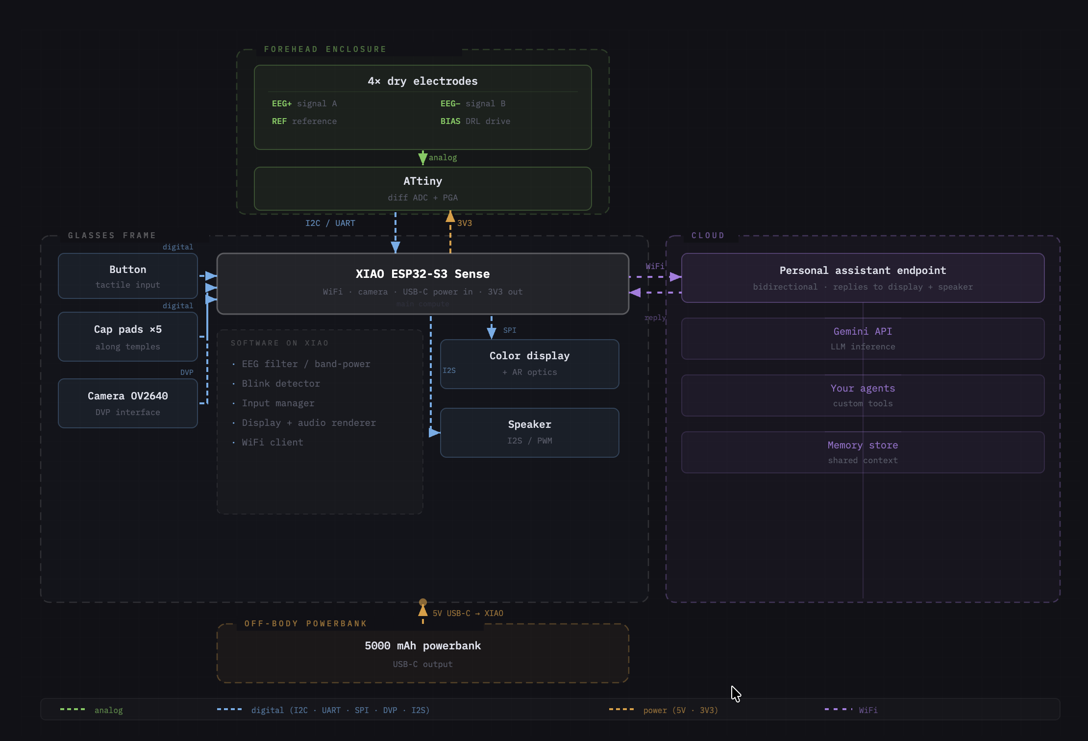
08: Systems Diagram and Project Planning
Around the machine-building period, I put together the systems diagram and the project timeline. That diagram became the clearest map of the project: electrodes, front-end, MCU, display, assistant path, power, and future spirals.
The machine week itself was a group build, so it was not directly the glasses. Still, it changed how I thought about mechanisms, rails, repeatability, and modular systems, and the same period is when the EEG signal detection work through the XIAO and SAMD11C14A from the previous section kept moving.
Planning-wise, this is also where the spiral structure on the final project page got locked in: a working test board first, then a wearable, then software, then integration with other hardware.
09: Interface Loop and the First DIY EEG Test Bench
The interface spiral is where the project started behaving like a complete loop. The hardware stack was still rough: electrodes into the op-amp/filter side, analog output into the SAMD11 ADC, then packets from the SAMD11 to the XIAO ESP32-S3 over I2C, and from there into a browser dashboard.
For this test bench, the SAMD11 packet grew up a little compared with the Spiral 0 board. It moved to address 0x10 and exposed a richer structure:
struct EegPacket {
  uint16_t magic;
  uint16_t seq;
  uint32_t sampleUs;
  uint16_t raw;
  uint16_t flags;
};
That packet shape mattered because the dashboard needed more than a random number. magic tells the XIAO if the read is aligned, seq shows skipped samples, sampleUs gives timing, raw is the ADC value, and flags leaves room for state.
The XIAO became the hub: WiFi, USB serial, camera, microphone, OLED, button input, and the I2C bridge to the SAMD11. The dashboard could connect over USB (Web Serial at 921600 baud) or WiFi and show the board state, camera frames, OLED commands, audio events, and EEG packets.
Every complete JSON line from the board goes into one event handler, and that one pattern carried the whole interface:
function handleSerialLine(line) {
  if (!line.startsWith('{')) return logEvent(`serial: ${line}`);
  handleBoardEvent(JSON.parse(line));
}
The board side exposed matching HTTP routes and serial commands, so USB was for setup and debugging while WiFi handled camera frames and live status:
/status /config /frame /capture /oled /eeg /gemini

The blink-training flow worked as an interface: calibrate a baseline, train on clear blinks, then test detection with a live threshold. But the analog signal was not amplified enough, and a lot of what moved on the plot was noise, contact changes, or motion artifacts. I also tried the same threshold logic with EMG from my wrist, and it only kind of worked for hard clenches.
It absolutely moved the project forward though, because it proved the software shape: small sampler chip, XIAO hub, browser dashboard, OLED feedback. That same shape stayed useful after the front-end changed completely.
The full breakdown of the dashboard, the mic and Gemini flow, the camera path, the OLED text/bitmap paths, and the teleprompter is in the Week 15 page.
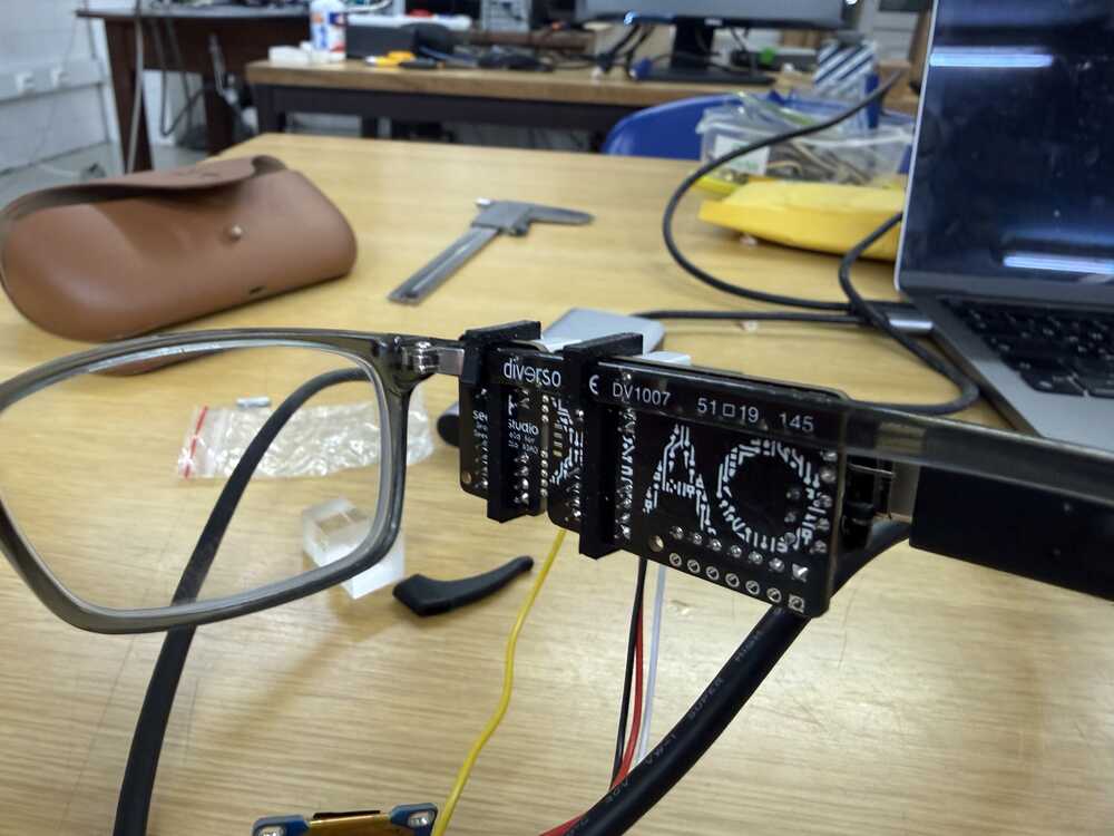
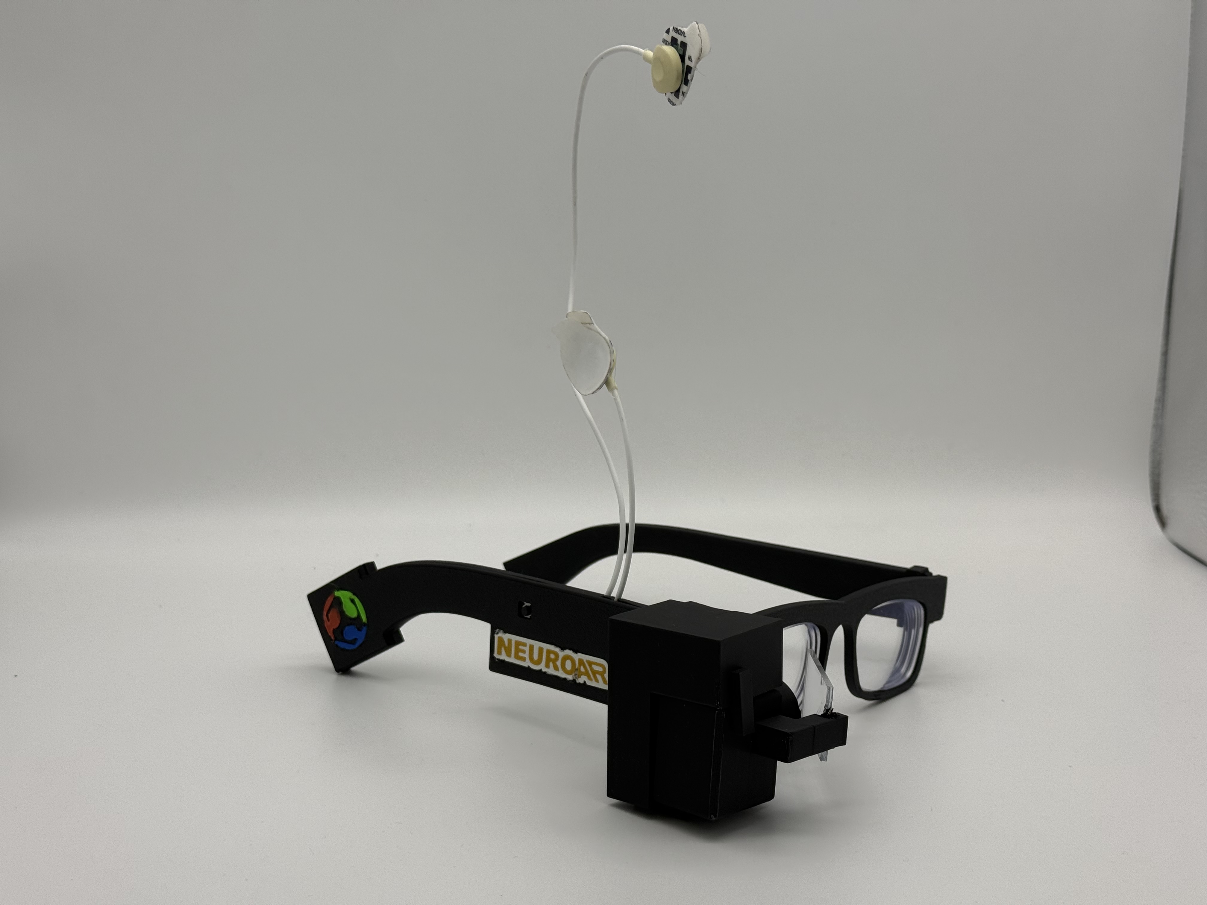
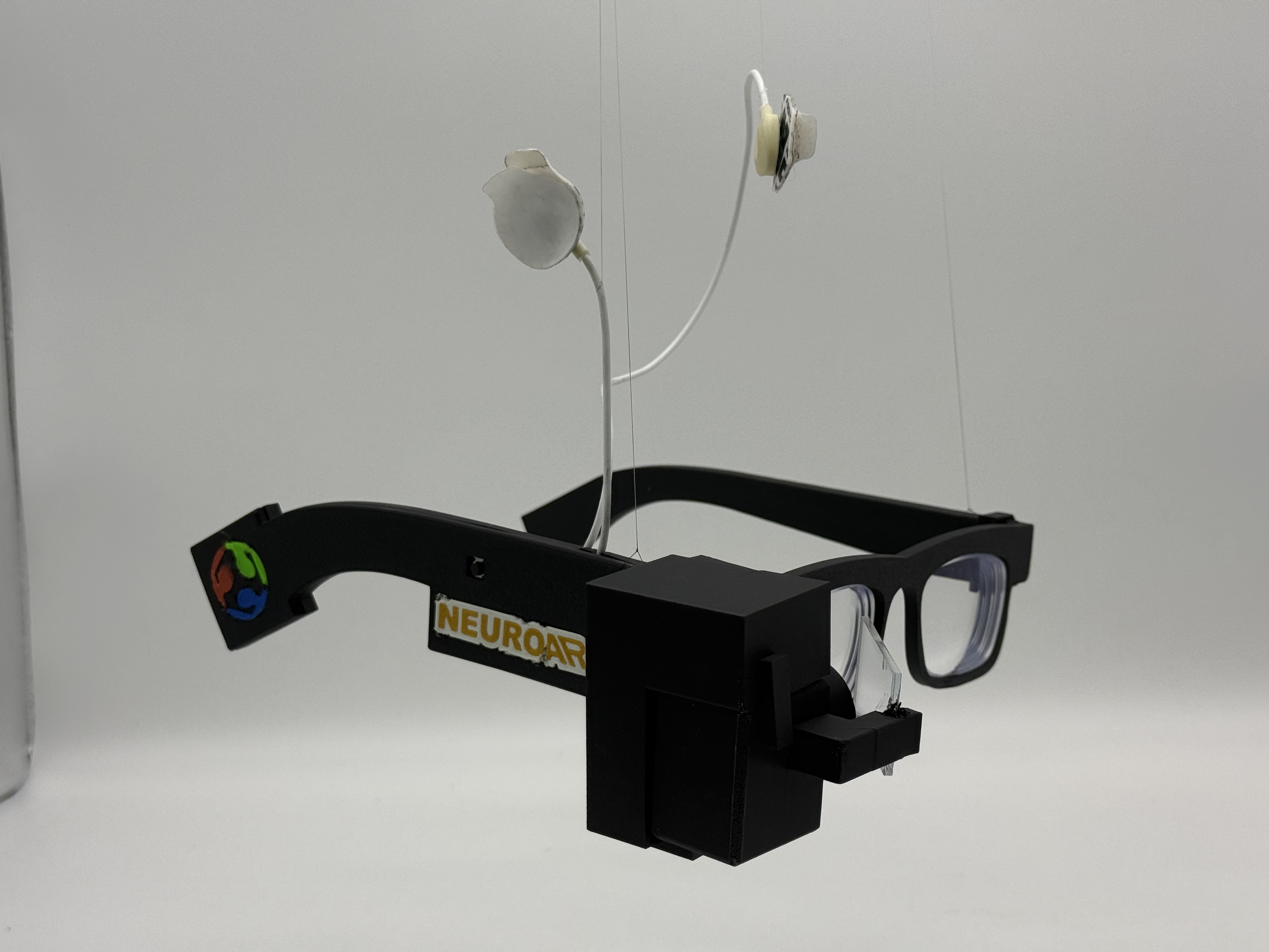
10: Integrated Wearable and the ADS1292 Board
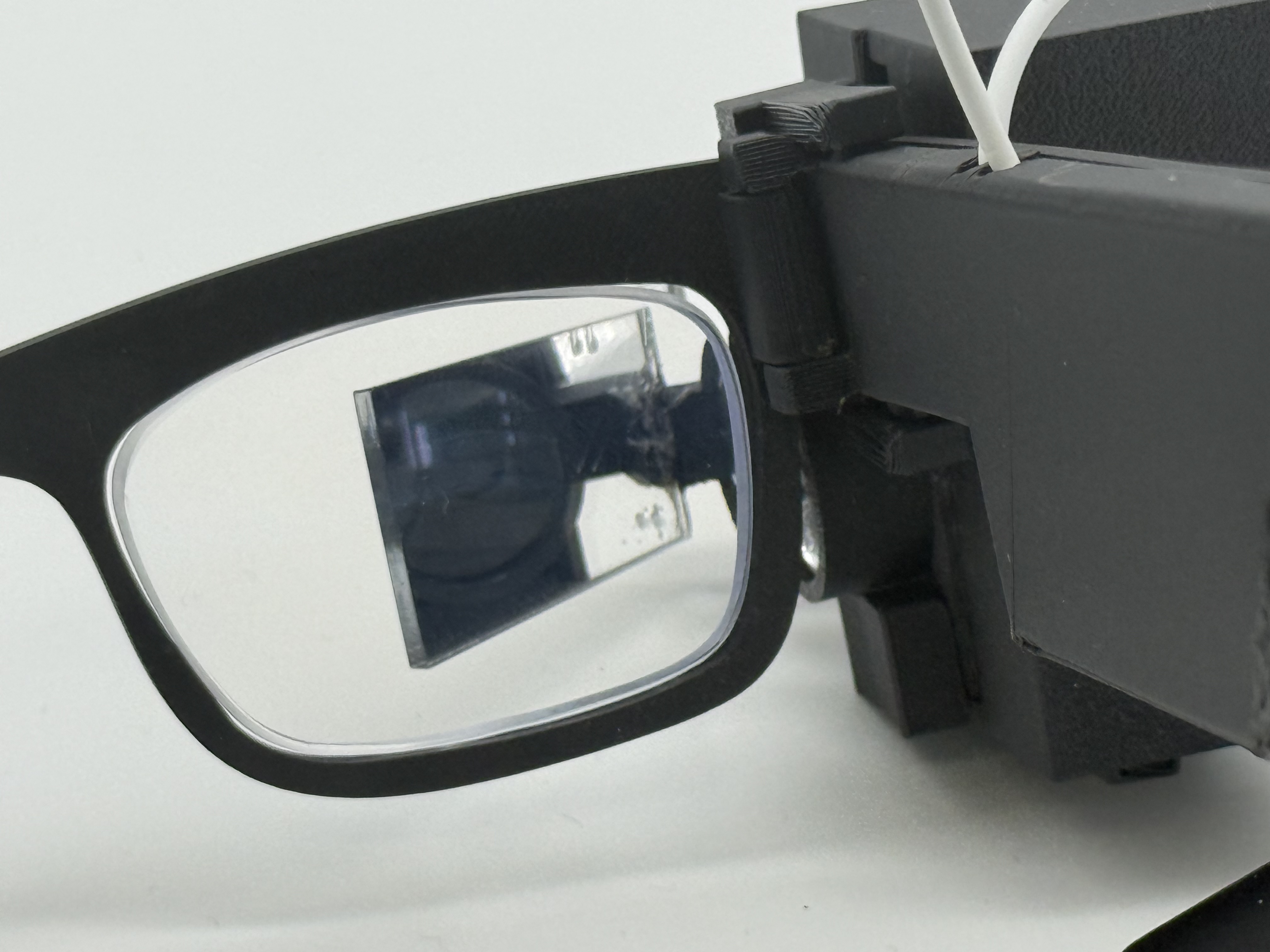
The next big spiral was system integration: the custom glasses chassis, detachable AR display/optics module, snap-fit packaging, cable concealment, and the ADS1292-based board, all coming together as one wearable prototype.
The mechanical change was designing from my actual lenses and face instead of from a generic glasses idea. I traced my lenses into a DXF, imported them into Fusion, and built the frame outward from there. The right temple became the electronics enclosure, the display module became detachable, and the wire concealers became part of the design instead of an afterthought.
Everything snaps. No screws. The temple cover, the display module, the prism holder, and the wire concealers all click into place, which also keeps the cables hidden.
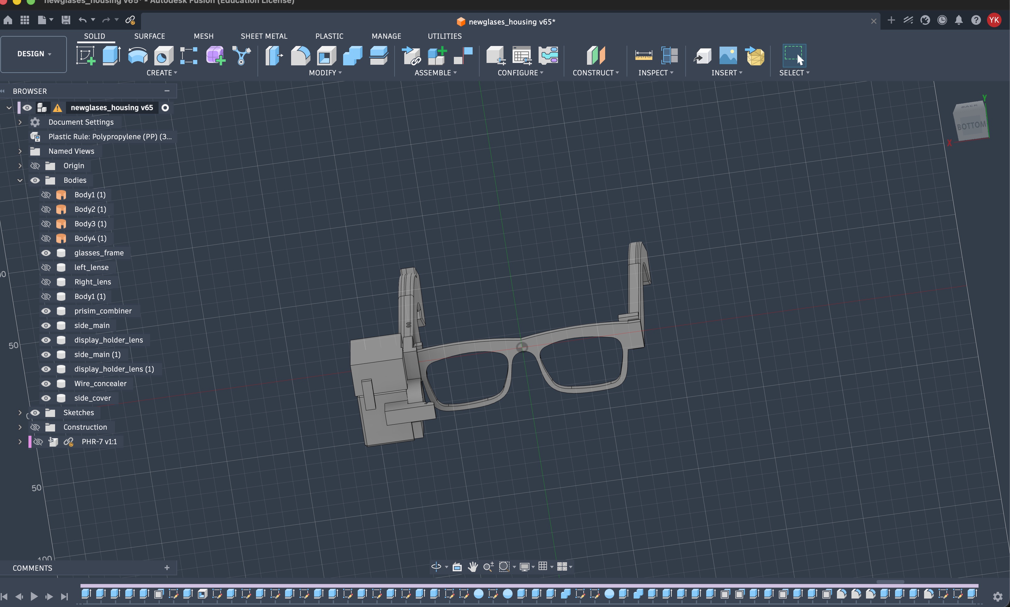
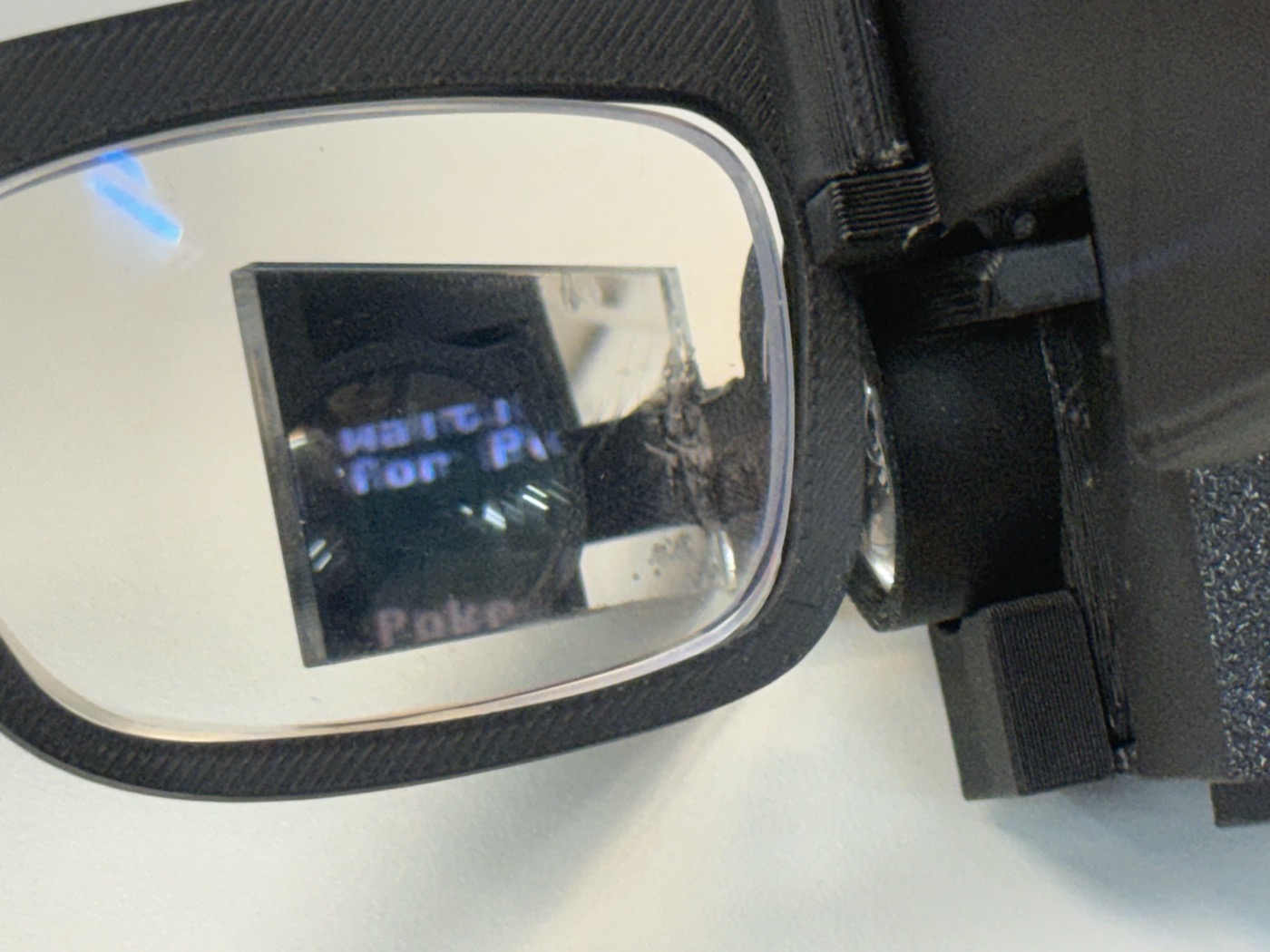
The display path became more compact too. The OLED, convex lens, prism, and mirror-acrylic combiner all had to line up physically. The lens roughly halved the distance the light needs before the prism, the prism redirects the light, and the angled mirror acrylic reflects it into my eye while leaving the forward view mostly clear.
The electronics moved away from the Week 15 op-amp + SAMD11 path. That first path was useful for learning, but it was too messy and unreliable for a wearable. The ADS1292 is made for biopotential sensing: differential input, gain, a 24-bit ADC, reference circuitry, and SPI.
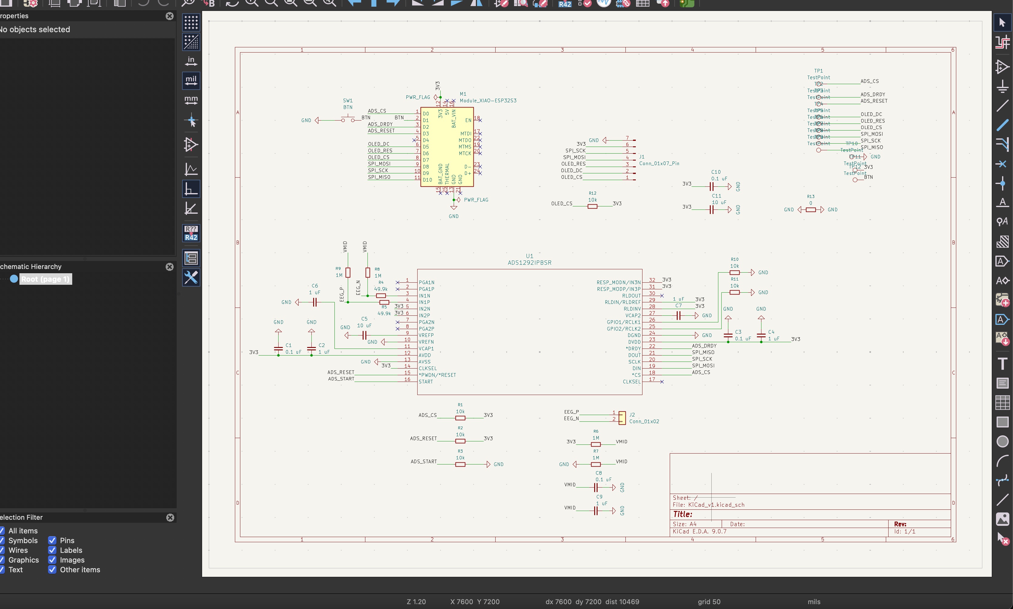
The schematic choices that make the circuit work: 49.9k resistors right after the electrode connector as protection between my body and the chip, 1M resistors from the electrode inputs to a VMID midpoint so the inputs can't float and saturate the chip, VMID itself made from a 1M/1M divider and smoothed with capacitors, bypass capacitors at every chip, and 10k resistors holding the control lines in a known state while the XIAO boots.
Milling it was its own story. The ADS1292 comes in a 32-TQFP package with 0.2 mm traces, and I ruined the first board and chip trying to clean solder off those traces. The second attempt, with better settings worked out with Yuichi and more patience, came out clean.
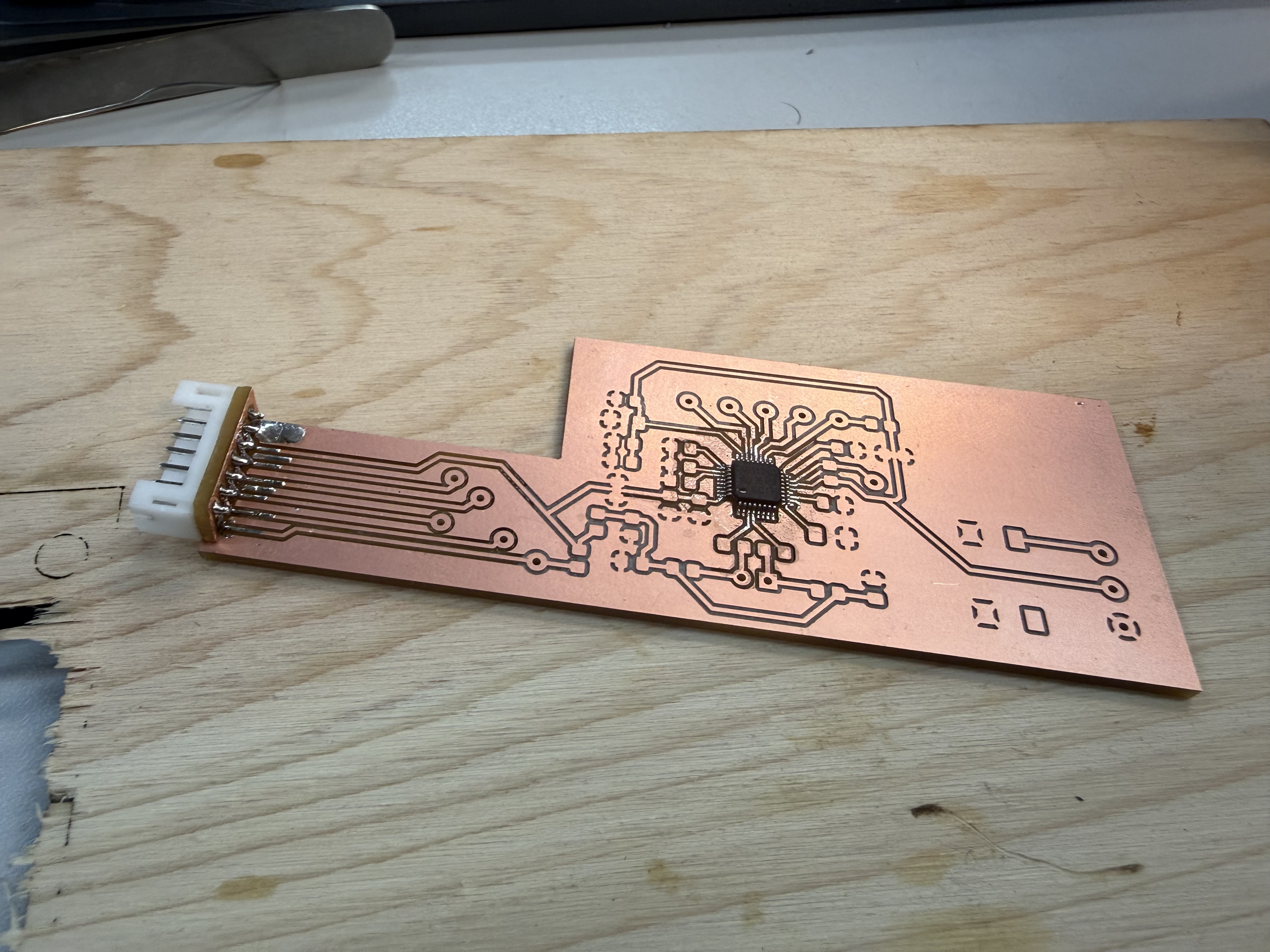
This spiral does not magically mean perfect EEG. The goal was detecting strong forehead signals reliably first: blinks, eye movement, and other large biopotential changes. Clean EEG stayed the direction, not the claim.

The full build with every iteration and failure is on the Week 16 page.
11: Refining the Glasses After Spiral 1
After wearing and testing the Spiral 1 build for a while, I went back into Fusion and reworked the body. The glasses got a bit thinner, the display connector slot got fixed, and the cover changed for a reason I did not expect: WiFi.
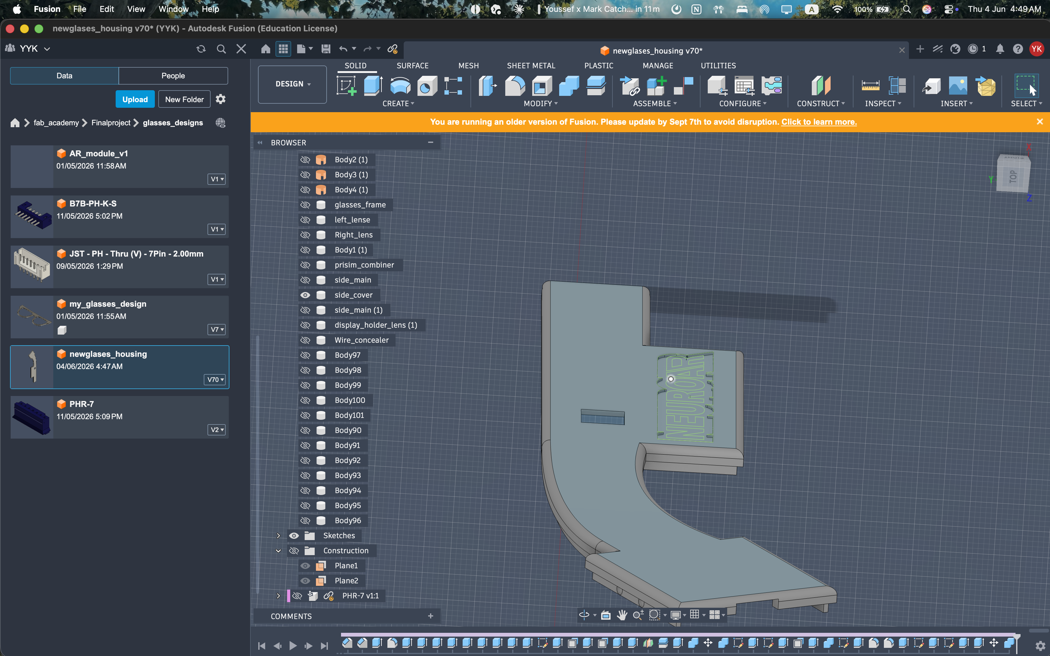
The first temple was around 6 mm deep including the cover, and it read as chunky on the face. The refined version slims the temple and the front, which also dropped a bit of weight off the nose.
The connector bit was the second fix. The slot for the display module connector never sat quite right in the first version, so the module could be pushed slightly off its seat. I reworked the clearances and chamfers so the connector lands cleanly and the module snaps in at the same depth every time.
The cover change is my favorite fix. The XIAO sits inside the right temple, and its WiFi antenna ends up firing through the cover. With the original cover thickness and infill, the signal to the dashboard was noticeably weaker than the bare board. I made the cover thinner and reduced its print infill, so there is simply less plastic between the antenna and the router, and the connection got better.
The last change was fillets. The first version only had fillets on the outside edges, for comfort and looks. The refined version adds fillets to the inside corners too. An inside corner without a fillet is a stress concentration, which is exactly where my early snap fits and thin walls were cracking, so the inside fillets make the parts a little stronger without changing how they look.
I fixed the spaghetti wiring mess inside the glasses' temples by bundling similar length wires together.
12: Customizing the Glasses and the Powerbank
With the body settled, I gave the glasses some identity. I added shallow recesses to the 3D-printed temples and printed matching inserts that drop into them: a NeuroAR wordmark, the project logo, and a Fab Academy emblem. The powerbank got a vinyl-cut sticker to match.
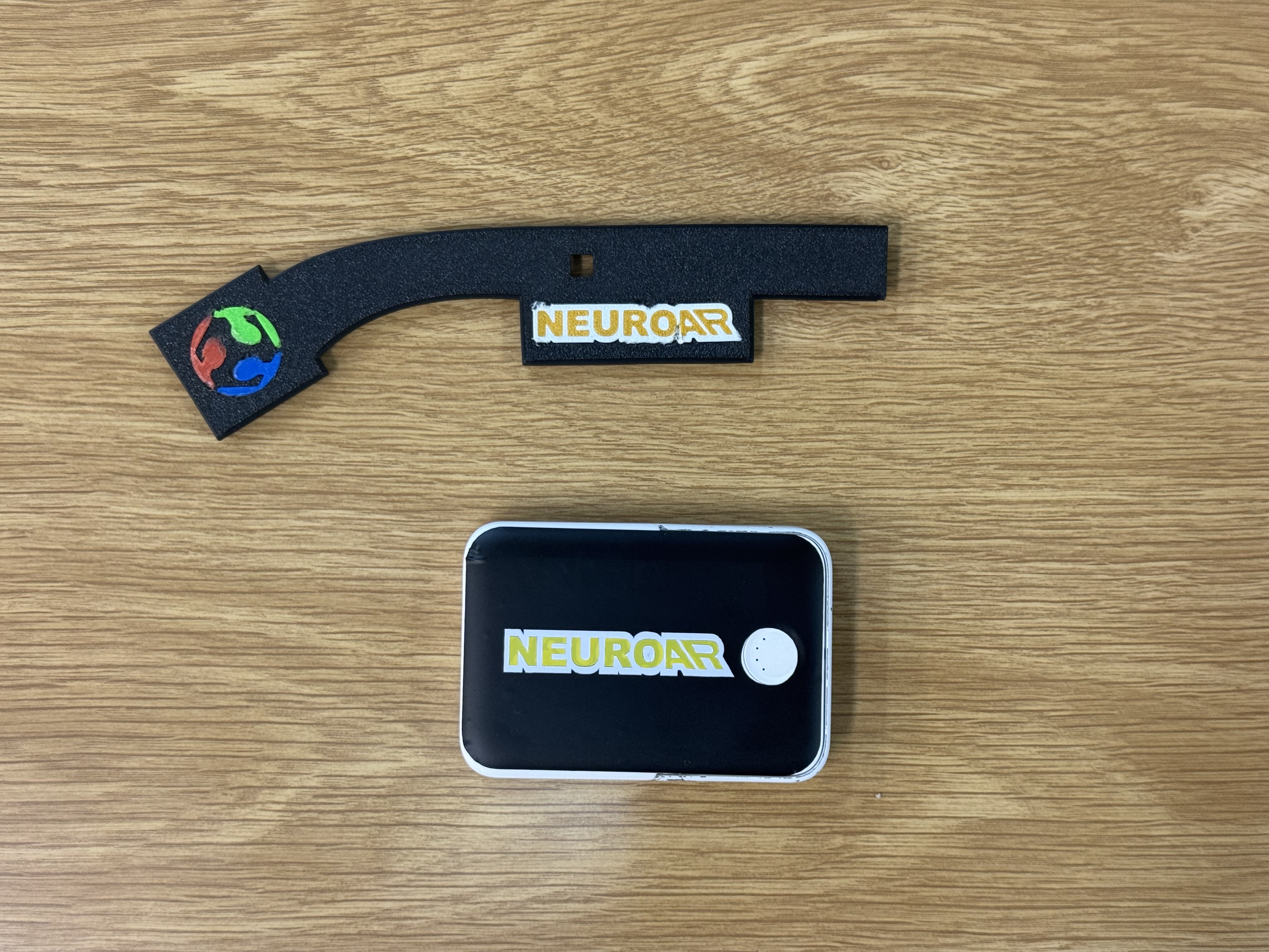
On the glasses themselves, the wordmark, logo, and Fab Academy emblem are 3D printed, set into shallow recesses in the temple so they sit flush instead of on top. Because the recess sets the position, the placement is repeatable, the recess is the registration, and there is no sticker edge to peel when the glasses go in and out of a bag.
The powerbank is where the vinyl cutter came in. NeuroAR runs off a small Anker 5000 mAh powerbank over USB-C from the back of the right temple, so it is effectively part of the product. I designed a cut-ready sticker sheet for it in Inkscape, with the wordmark sized for the powerbank face, and cut it on the vinyl cutter.
It is a small spiral compared with the electronics, but it is the difference between "a prototype with a battery hanging off it" and an object where even the battery looks like it belongs.
13: EEG on the Board: MicroPython and the ADS1292
Spiral 2 is software. After the physical build, I rebuilt the EEG runtime as a MicroPython-first project on the XIAO ESP32-S3, reading the ADS1292 directly over SPI and turning the signal into features on the board itself.
The pipeline on the board is:
- The ADS1292 samples one differential channel over SPI, configured for the internal reference, 500 SPS, and gain 6.
- The XIAO buffers windows of about one second and downsamples to 250 Hz.
- MicroPython extracts seven single-channel features with Goertzel filters.
- A trained feature transform feeds a small linear readout.
- Leaky integrate-and-fire output neurons turn that into a predicted state.
Bringing up the ADS1292 over SPI
The ADS1292 is an SPI device with a small command set (WAKEUP, STOP, SDATAC, RREG, WREG, START, RDATAC). The bring-up sequence is fussy: you hardware-reset it, stop continuous read mode so you can talk to registers, write the config, and then a step I did not want to skip, read those registers back and refuse to run if they do not match what I wrote.
def begin(self):
    self.hardware_reset()
    self.command(CMD_WAKEUP)
    self.command(CMD_STOP)
    self.command(CMD_SDATAC)          # stop continuous read so RREG/WREG work

    self.id = self.read_register(REG_ID)
    if self.id in (0x00, 0xFF):
        raise RuntimeError("ADS1292 did not return a usable ID: 0x%02X" % self.id)

    self.write_register(REG_CONFIG1, CONFIG1_500_SPS)        # 0x02 -> 500 SPS
    self.write_register(REG_CONFIG2, CONFIG2_INTERNAL_REF)   # 0xA0 -> internal ref on
    self.write_register(REG_CH1SET, CH_GAIN6_NORMAL_ELECTRODE)
    self.write_register(REG_CH2SET, CH_GAIN6_NORMAL_ELECTRODE)

    # readback verification: if any register is wrong, stop here instead of
    # streaming garbage that looks like EEG
    if self.read_register(REG_CONFIG1) != CONFIG1_500_SPS or ...:
        raise RuntimeError("ADS1292 register readback failed: ...")

    self.command(CMD_START)
    self.command(CMD_RDATAC)          # back into continuous read mode
    return self.id
The readback check is the same instinct as the magic byte on the Spiral 0 board and the sequence numbers in the music player: never trust that the other side is in the state you think it is. A floating SPI line happily returns 0x00 or 0xFF, and an unverified config will stream numbers that look plausible and mean nothing.
SPI mode matters too. The ADS1292 wants mode 1 (polarity=0, phase=1), so the MicroPython SPI object is set up that way, and because the OLED shares the same bus at a different mode, the driver re-inits the bus settings every time it selects the chip.
Reading a frame
In continuous mode, the ADS1292 pulls its DRDY line low when a fresh sample is ready. Each sample is 9 bytes: a 24-bit status word, then two 24-bit signed channels. The driver only reads when DRDY is low, does one 9-byte transfer, and sign-extends the 24-bit values into normal signed integers:
def read_frame(self):
    if self.drdy.value() != 0:
        return None
    self._select()
    self.spi.write_readinto(self._tx9, self._rx9)   # 9-byte full-duplex transfer
    self._deselect()

    status = (self._rx9[0] << 16) | (self._rx9[1] << 8) | self._rx9[2]
    ch1 = _sign_extend_24((self._rx9[3] << 16) | (self._rx9[4] << 8) | self._rx9[5])
    ch2 = _sign_extend_24((self._rx9[6] << 16) | (self._rx9[7] << 8) | self._rx9[8])
    return status, ch1, ch2
The raw counts become microvolts with the standard ADS1292 scale, reference voltage divided by gain, spread across the signed 24-bit range:
COUNTS_TO_UV = (config.VREF_VOLTS / config.PGA_GAIN) * 1_000_000.0 / 8388607.0
The main loop
The whole runtime is one cooperative loop: poll serial commands and the button, service WiFi, then if a frame is ready, read it, downsample, and feed the feature window. Because everything shares one loop, every step has to return fast or the EEG stalls.
while True:
    control.poll(ads)            # serial commands from the dashboard
    wifi.poll()                  # keep WiFi/NTP alive
    display.tick()               # render the current OLED page

    if not ads.wait_drdy():
        emit("WARN,ads_drdy_timeout,frames=%d" % ads.frames)
        continue
    frame = ads.read_frame()
    if frame is None:
        continue

    _, eeg_counts, diag_counts = frame
    eeg_uv = counts_to_uv(eeg_counts)

    downsample_count += 1
    if downsample_count < config.DOWNSAMPLE:   # 500 SPS -> 250 Hz
        continue
    downsample_count = 0

    features = extractor.add_sample(eeg_uv)    # returns a row once the window fills
    if features is None:
        continue
    if control.model_enabled:
        prediction, confidence, _, _ = model.predict(features)
    emit(feature_row(ticks_ms(), ads.frames, prediction, confidence, features))
The feature row is deliberately simple:
eeg_delta, eeg_theta, eeg_alpha, eeg_beta, eeg_gamma, eeg_rms, blink_peak
The feature pipeline has a name, detrend_hann_clip_v3, and the name travels with every trained model. Each window removes its mean and linear trend, clips the detrended signal to ±250 uV so a single artifact can't dominate, and uses a Hann-tapered copy for the band powers:
FEATURE_PIPELINE = "detrend_hann_clip_v3"
ARTIFACT_CLIP_UV = 250.0

BANDS = (
    (1.0, 4.0),    # delta
    (4.0, 8.0),    # theta
    (8.0, 13.0),   # alpha
    (13.0, 30.0),  # beta
    (30.0, 45.0),  # gamma
)
If the pipeline name on the firmware and the pipeline name inside the deployed model do not match, the board disables predictions instead of quietly running a model on features it was never trained for.
The band powers themselves come from Goertzel filters, not a full FFT. A Goertzel evaluates the energy at one frequency bin with a single coefficient and two state variables, so for one EEG band I sum a handful of bins and it costs far less RAM than an FFT on the ESP32-S3:
def _band_power(self, samples, coeffs):
    total = 0.0
    n = len(samples)
    for coeff in coeffs:                 # one coeff per frequency bin in the band
        s_prev = 0.0
        s_prev2 = 0.0
        for x in samples:                # Goertzel recurrence
            s = x + coeff * s_prev - s_prev2
            s_prev2 = s_prev
            s_prev = s
        power = s_prev2 * s_prev2 + s_prev * s_prev - coeff * s_prev * s_prev2
        total += power / (n * n * self._hann_power)
    return total / len(coeffs)
Each window is detrended (mean and linear slope removed), clipped to ±250 uV, Hann-tapered for the band powers, and then the five band powers plus RMS and blink-peak are each passed through log10(1 + x) so the scale is compressed:
def extract(self, eeg):
    eeg_clean = self._limit_artifacts(self._detrend(eeg))
    eeg_tapered = self._taper(eeg_clean)
    features = [ _safe_log10p(self._band_power(eeg_tapered, c)) for c in self._band_bins ]
    # ... then RMS and blink_peak from eeg_clean, also log-compressed
    return features
Everything the board says goes over USB serial as typed rows, which is what the dashboard parses:
RAW,ms,frames,eeg_uv,diag_uv
FEATURE,ms,frames,prediction,confidence,f0,...,f6
STATUS,ms=...,model=...,model_ready=...,feature_pipeline=...,classes=...
Only eeg_uv is used for features and training. The second ADS1292 channel is plotted as diag_uv so the unused channel is visible instead of being mistaken for a second EEG electrode.
Here is a short clip of the live EEG signal coming off the board:
Why MicroPython and not C? Because this first model is intentionally small, spectral features plus a spiking readout, and MicroPython let me iterate on the board logic in minutes. If a later spiral needs a CNN, the runtime moves to native ESP-IDF, but the point of this spiral was collecting data and validating the idea without writing C first.
14: The LIF-SNN System
This is the brain-inspired part of the project, and it is software, not an analog circuit. A small LIF-SNN classifier runs on the XIAO, trained offline in Python on my own recordings and flashed to the board as a generated weights file.
The on-board model is a trained linear readout feeding leaky integrate-and-fire output neurons, one neuron per class. Each prediction step, every neuron's membrane integrates the class probability, leaks, and fires when it crosses threshold:
def predict(self, features):
    logits = self._logits(features)
    probs = self._softmax(logits)

    for i, p in enumerate(probs):
        self.membrane[i] = self.membrane[i] * self.leak + p
        spiked = 0.0
        if self.membrane[i] >= self.threshold:
            spiked = 1.0
            self.membrane[i] -= self.threshold
        self.spike_rate[i] = self.spike_rate[i] * self.spike_decay + spiked
The winning class is scored by spike rate plus probability, so a single noisy window can't flip the prediction. The membrane has to charge up across windows first. That is the same integrate, leak, threshold, reset behavior I once built from op-amps in section 05, now doing useful work on the EEG stream.
Before the spiking layer there is a plain linear readout. The class probabilities come from normalizing each feature against the mean and scale the trainer exported, clipping outliers, and running a softmax over per-class weighted sums:
def _logits(self, features):
    features = self._transform(features)
    x = []
    for i in range(mw.FEATURE_COUNT):
        value = (features[i] - mw.FEATURE_MEAN[i]) / mw.FEATURE_SCALE[i]
        x.append(max(-8.0, min(8.0, value)))        # clip so one bad feature can't dominate

    logits = []
    for c in range(mw.CLASS_COUNT):
        value = mw.BIASES[c]
        for i in range(mw.FEATURE_COUNT):
            value += mw.WEIGHTS[c][i] * x[i]
        logits.append(value)
    return logits
So the spiking neurons sit on top of a softmax classifier: the linear layer gives a per-window probability, and the LIF layer turns that into a stable prediction over time. The leak, threshold, and spike decay are all tunable live from the dashboard:
THRESHOLD <value>
LEAK <value>
SPIKE_DECAY <value>
The model that gets flashed is just a generated Python file of constants, no framework on the board. The trainer writes the class names, the per-feature mean and scale, the weight matrix, the biases, and crucially the pipeline and transform names so the firmware can refuse a mismatched model:
# model_weights.py, generated by tools/train_snn.py
MODEL_SOURCE = "trained"
FEATURE_PIPELINE = "detrend_hann_clip_v3"
FEATURE_TRANSFORM = "relative_bands_peak_v1"
CLASS_NAMES = ('blink', 'eyes_closed', 'rest')
FEATURE_MEAN  = (0.0580, 0.0114, -0.0342, -0.0109, -0.0244, 2.3997, 0)
FEATURE_SCALE = (0.1958, 0.0850,  0.1040,  0.0911,  0.1109, 1, 1)
WEIGHTS = ( (...class 0...), (...class 1...), (...class 2...) )
BIASES  = (0.2708, -0.5084, 0.2376)
Training happens on the laptop in plain NumPy, no deep-learning framework. It is a softmax (multinomial logistic) classifier trained by gradient descent: normalize the features, run softmax, take the cross-entropy gradient, and step the weights with a little L2 regularization:
for _ in range(epochs):
    logits = x_norm @ weights.T + biases
    probs = softmax(logits)
    error = probs - y_onehot
    grad_w = error.T @ x_norm / len(x_norm) + l2 * weights
    grad_b = error.mean(axis=0)
    weights -= lr * grad_w
    biases  -= lr * grad_b
The mean and scale used to normalize during training are exactly what gets exported into the weights file, so the board normalizes each feature the same way the trainer did.
The trainer defaults to --transform auto: it trains both the raw features and a transform called relative_bands_peak_v1, scores each with leave-one-row-out validation, and exports whichever wins:
def evaluate_leave_one_out(x, y, ...):
    predictions = []
    for held_out in range(len(x)):                 # train on every row but one
        train_idx = [i for i in range(len(x)) if i != held_out]
        mean, scale, w, b = train_with_normalization(x[train_idx], y[train_idx], ...)
        predictions.append(predict_classes(x[[held_out]], mean, scale, w, b, ...)[0])
    return accuracy(predictions, y), confusion_matrix(...)
Leave-one-row-out matters because the dataset is tiny: a normal train/test split would waste rows, so training on all-but-one and testing on the held-out row, repeated for every row, gives the most honest accuracy estimate I can get from a few dozen samples.
relative_bands_peak_v1 converts the five band features to relative band shape (each band minus the band mean), keeps RMS absolute, and turns blink peak into peak-minus-RMS. The point is to be less sensitive to electrode gain and contact, which change every time the electrodes go back on:
x[:, :5] = x[:, :5] - x[:, :5].mean(axis=1, keepdims=True)  # relative band shape
x[:, 6] = x[:, 6] - x[:, 5]                                  # blink peak above RMS
With my small saved dataset, the relative transform was selected:
- leave-one-row-out accuracy around
0.711, - majority-class baseline around
0.600, - weak spot: blink rows often predicted as rest,
- data problem: blink and eyes-closed each came from only one short recording file.
So the SNN beats a naive baseline on my own recordings, and the pipeline runs end to end from recording to on-board inference. But I am not claiming a reliable brain-state controller. The dataset is tiny, and the signal-quality check made the priority clear: one raw capture showed EEG RMS around 16818 uV and peak-to-peak around 246942 uV, which is far too large for clean EEG. The next improvement is physical, electrode contact, reference behavior, strain relief, and more balanced recording sessions, not a bigger model.
One design decision I want to keep from this: the firmware and dashboard hide prediction and confidence entirely while the heuristic starter weights are active. Predictions only appear after real trained weights are generated and deployed. The interface never pretends the model is better than the data.
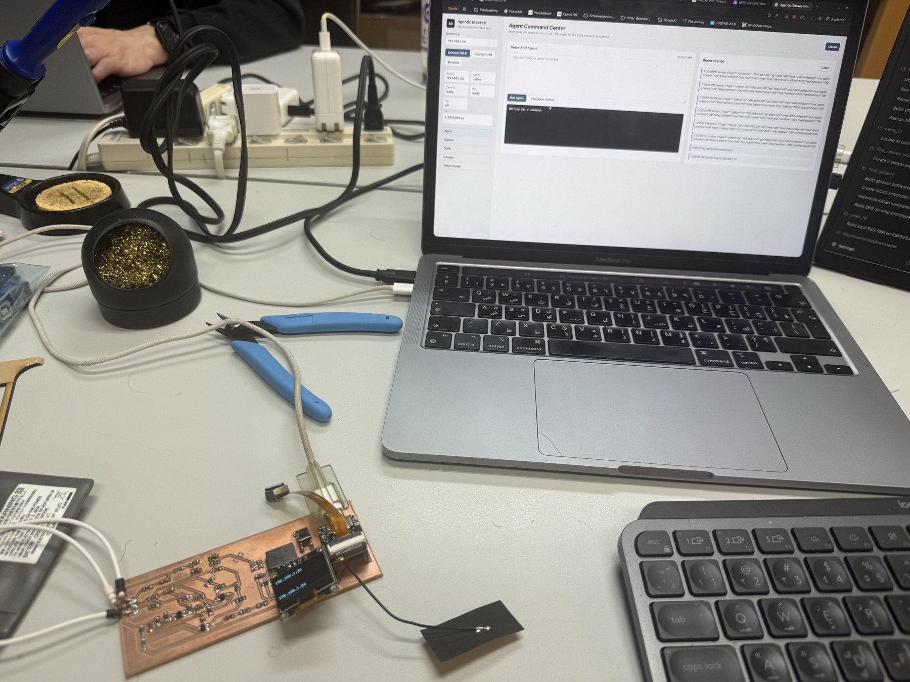
15: The Dashboard
The dashboard is the local control surface for the whole system. It is a browser app served by a small Node server, and it handles signal monitoring, recording, training, deployment, and the Display Studio in the next section.
The dashboard has four ways to reach the board, and it falls back gracefully between them:
- USB through browser Web Serial at 115200 baud.
- Server USB, where the Node server holds the serial port and streams rows to the browser. This is for when Web Serial is unavailable or laggy.
- WiFi, opening a WebSocket to the board with the same line protocol.
- Simulate, which generates synthetic rows for testing the UI. Synthetic data is marked as simulation and never saved for training.
The USB path uses the browser Web Serial API directly. The board prints newline-delimited rows, so the read loop decodes the stream, buffers a partial line across reads, and hands each complete line to one dispatcher:
async function readSerialLoop() {
  const decoder = new TextDecoderStream();
  state.serialPort.readable.pipeTo(decoder.writable);
  state.serialReader = decoder.readable.getReader();
  let buffer = '';
  while (true) {
    const { value, done } = await state.serialReader.read();
    if (done) break;
    buffer += value;
    const lines = buffer.split(/\r?\n/);
    buffer = lines.pop() || '';            // keep the unfinished line for next read
    for (const line of lines) handleLine(line.trim());
  }
}
handleLine() is the heart of the dashboard. JSON lines are board events, and the comma rows are the typed protocol from the firmware. Everything routes by the first field:
function handleLine(line) {
  if (line.startsWith('{')) return handleJsonEvent(line);
  const parts = line.split(',');
  if (parts[0] === 'FEATURE') handleFeature(parts);
  else if (parts[0] === 'RAW') handleRaw(parts);
  else if (parts[0] === 'STATUS') handleStatus(parts);
  else if (parts[0] === 'WIFI') handleWifiStatus(parts);
  else logEvent(line);
}
The same dispatcher works no matter which transport delivered the line, USB, Server USB, or the WiFi WebSocket, because all three carry the identical row protocol. That is why adding the WiFi path later did not mean rewriting the parsing.
handleFeature() is where the honesty rule lives. A row only becomes a prediction if real trained weights are deployed; otherwise it is labelled untrained or simulation only, never a fake class. And when a real blink is predicted, it debounces and fires the on-screen control, the same blink that drives the display in the video above:
if (row.prediction === 'paused')        state.lastPrediction = 'model paused';
else if (state.modelTrained) {
  state.lastPrediction = row.prediction;
  if (row.prediction === 'blink' && Date.now() - state.lastBlinkAt > 500) {
    triggerBlinkControl();              // blink moves the paddle / page
  }
} else state.lastPrediction = 'untrained';
The Device Check panel reports the active port, board status, WiFi and time state, model source, dataset size, Gmail OAuth state, and missing firmware files. If the board got left at the MicroPython prompt, a Fix Basics button soft-resets the EEG app over USB and reapplies the display, time, and weather fallbacks.
The Raw EEG panel doubles as the signal-quality readout: live RMS, peak-to-peak, and a conservative readiness hint that warns when the amplitudes look dominated by contact, movement, blink, or reference noise.
Recording and training run entirely from the dashboard. The browser button is just the trigger, the real work happens on the Node server: Train + Deploy posts to /api/train, which spawns the same Python trainer I would run by hand, then /api/deploy copies the generated weights to the board with mpremote:
async function trainAndDeployModel() {
  const result = await postJson('/api/train', { epochs: 2400, lr: 0.08, l2: 0.001, seed: 42 });
  state.modelTrained = Boolean(result.model?.trained);
  if (state.serialPort) await closeUsb();          // free the port before mpremote grabs it
  const deploy = await postJson('/api/deploy', { port: selectedPort() });
}
// server side: /api/train spawns the trainer over the recorded CSVs
const args = ['tools/train_snn.py', '--data', ...files,
              '--out', 'firmware_micropython/model_weights.py', '--epochs', '2400', ...];
const result = await runCommand(pythonBin, args, { cwd: projectRoot, timeoutMs: 120000 });

// /api/deploy copies the model to the board over mpremote
for (const file of ['firmware_micropython/snn_model.py', 'firmware_micropython/model_weights.py']) {
  await runCommand(mpremoteBin, ['connect', portName, 'fs', 'cp', file, ':']);
}
The deploy route refuses to push if the active weights are still heuristic, so you cannot accidentally deploy the placeholder model. The Training Readiness box shows row counts per label and keeps the tiny-dataset problem visible instead of hiding it. If signal quality says very noisy, the right move is collecting cleaner readings, not training on artifacts, and the dashboard says so.
The Gmail widget is the one external integration with real authentication. An API key cannot read a private inbox, so the Node server runs an OAuth flow, and after consent the dashboard writes the real unread count and latest sender into a status file and pushes that to the board. Without OAuth it shows "OAuth needed" instead of fake unread counts.
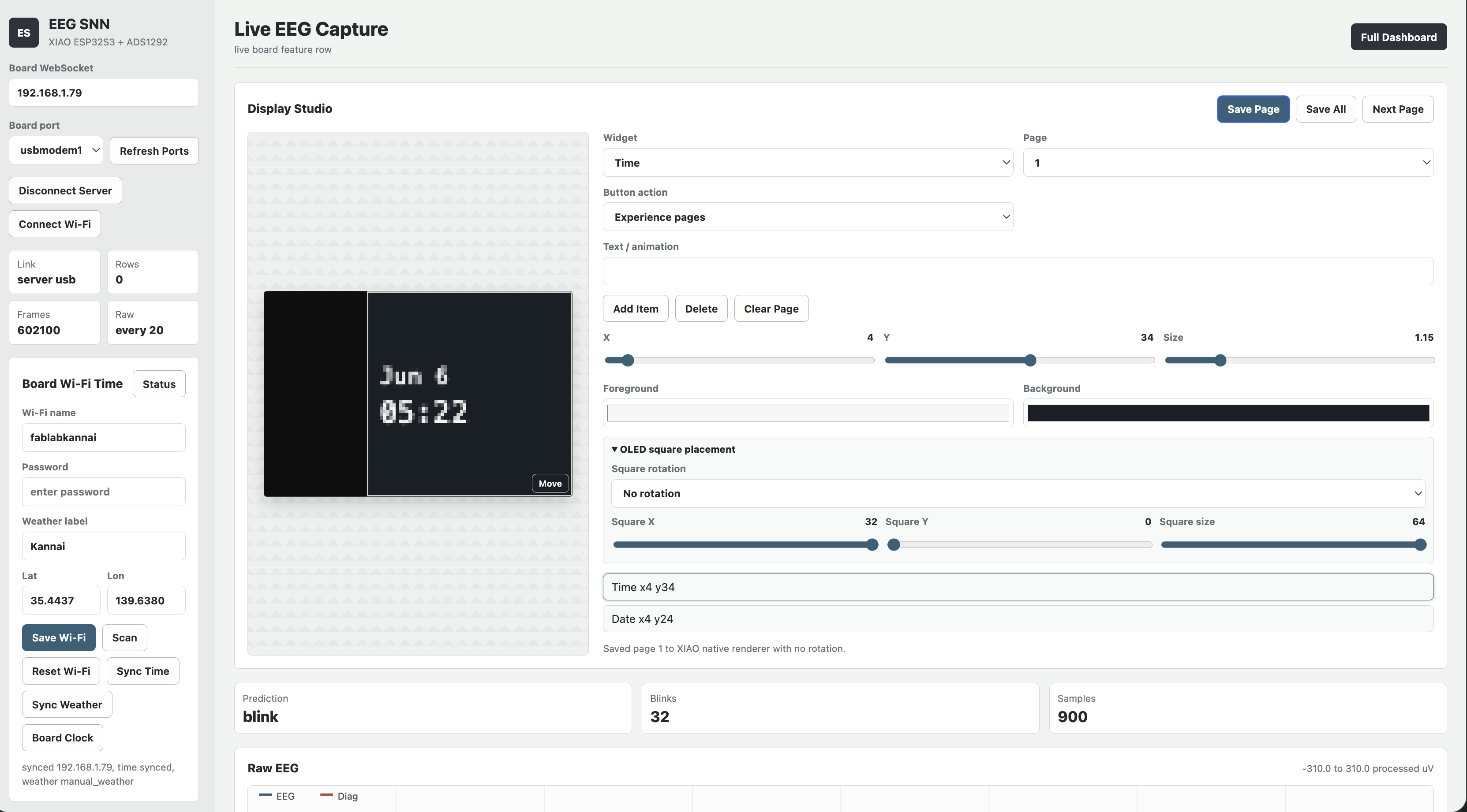
16: Display Studio
Display Studio is the part of the dashboard that controls what the glasses actually show. Instead of uploading laptop-rendered bitmaps, the better path became board-native widget pages that the XIAO renders itself.
The studio edits up to seven pages, and each page is built from standard widgets: time, date, weather text, custom text, animation, the EEG blink counter, blink Pong, and Button Jump. Save Page stores one page on the XIAO, Save All stores all seven and restores the selected page afterward.
Saving a page is a tiny chunked protocol over the same serial link. A page definition can be larger than one serial line, so the dashboard base64-encodes it and sends it as a begin/chunk/end sequence, and the firmware reassembles it:
elif command == "WIDGETS_BEGIN":
    self.display.begin_widgets(page)            # start collecting for this page
elif command == "WIDGETS_CHUNK":
    self.display.add_widgets_chunk(line[14:].strip())   # append base64 chunk
elif command == "WIDGETS_END":
    ok = self.display.end_widgets()             # decode + render, ACK ok/failed
The full command table the firmware understands is the same shape as the Week 15 board: typed text commands, each acknowledged. Beyond the widget chunks there are DISPLAY_VIEWPORT, DISPLAY_ROTATION, WEATHER_SYNC, TIME_SYNC, GMAIL_STATUS, and DISPLAY_DEFAULTS, each with an ACK so the dashboard knows it landed.
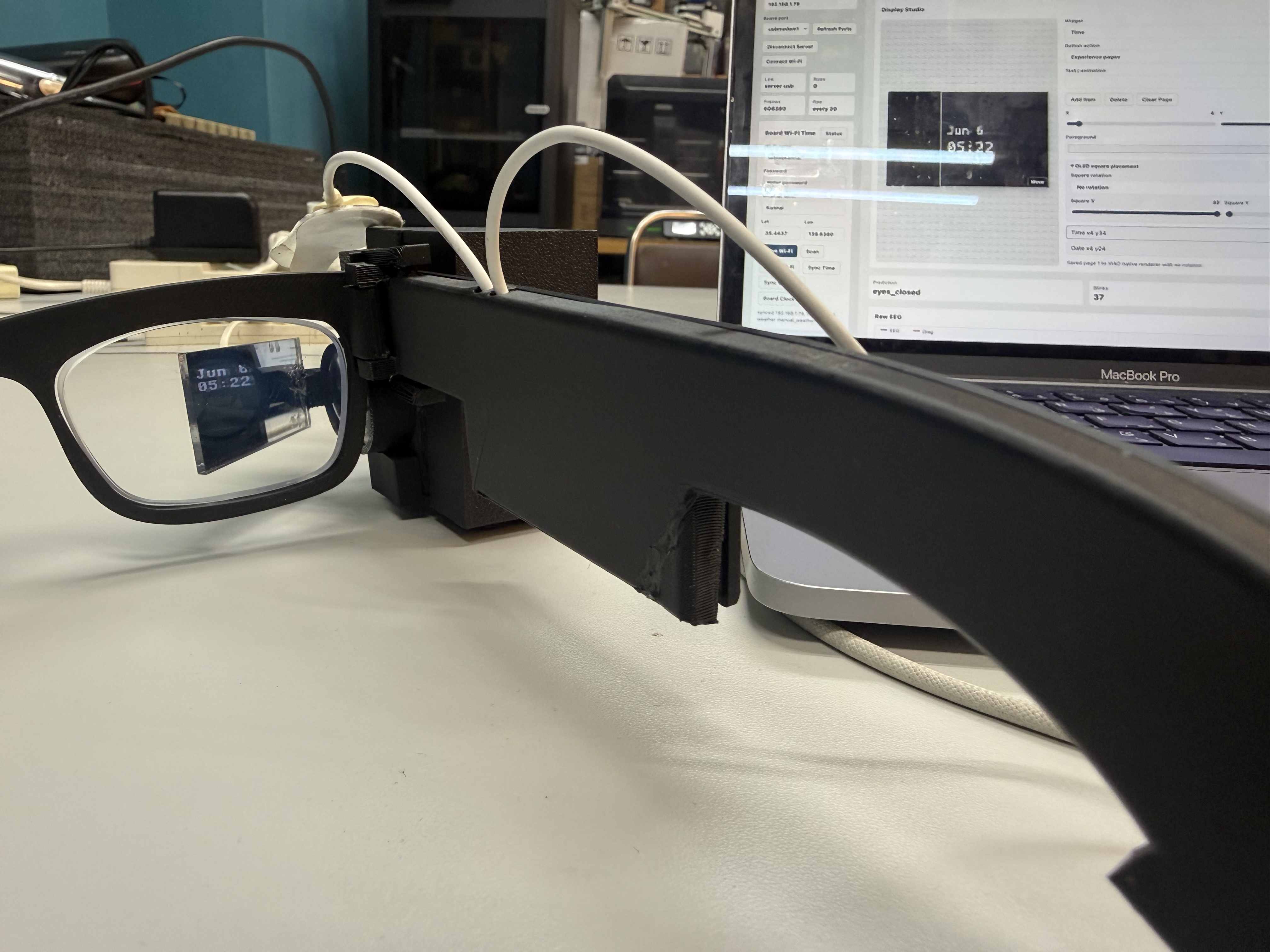
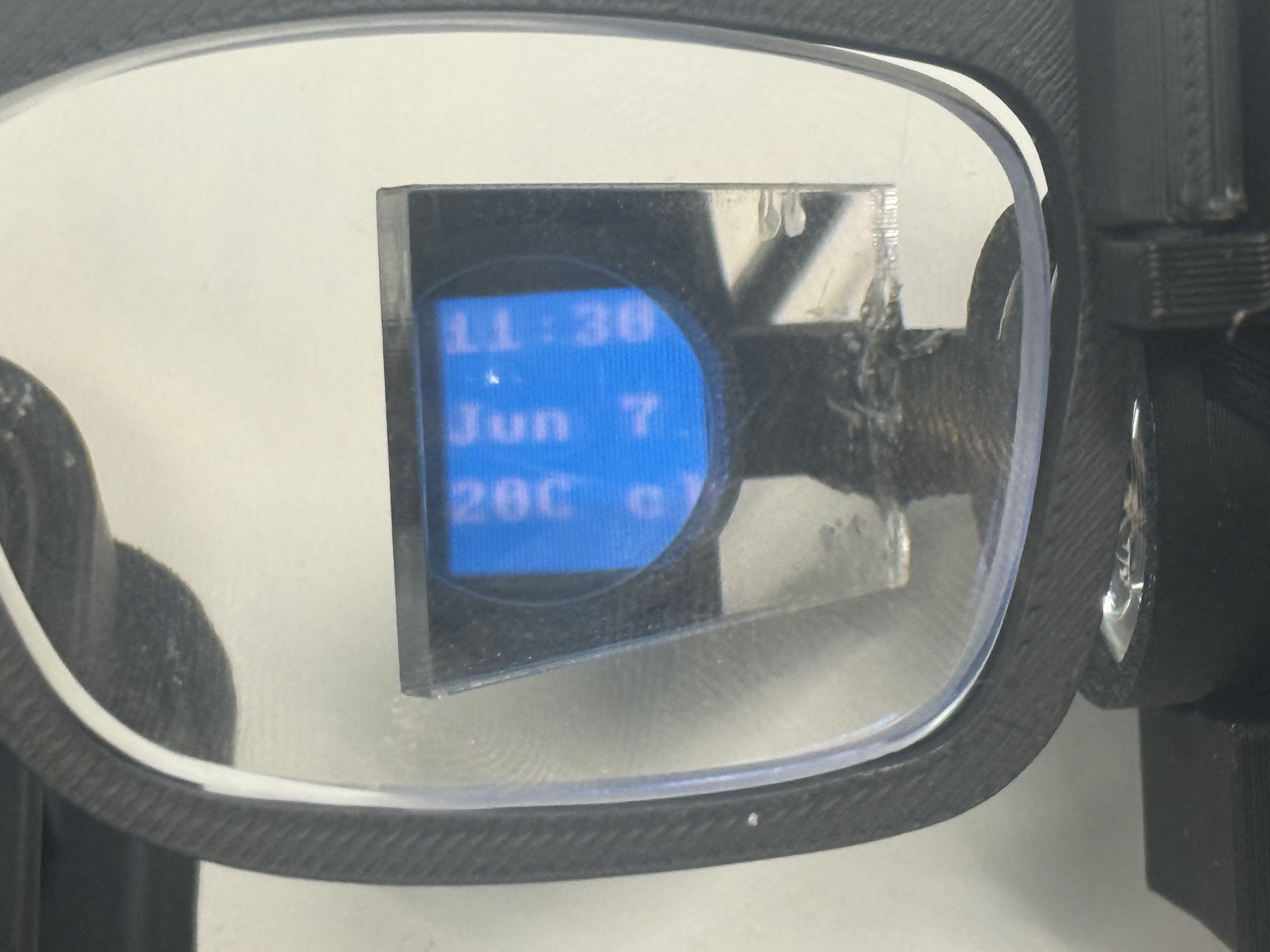
Time and weather come from the XIAO's own WiFi
The clock and weather page above is not the laptop pushing values to the board. The XIAO syncs both itself over its own WiFi, so the glasses keep working as a clock with the dashboard closed.
For time, the XIAO joins WiFi as a station, then sets its real-time clock from an NTP server and applies my timezone offset. The hardware RTC holds the time between syncs, and the firmware re-syncs every six hours so it never drifts far:
def sync_time(self):
    import ntptime
    ntptime.settime()          # pulls UTC from an NTP server onto the RTC
    self.synced = True
    self.status = "synced"

def local_time(self):
    # RTC time + timezone offset, applied on the board
    return localtime(time() + self.timezone_offset_hours * 3600)
For weather, the XIAO makes its own HTTP request straight to the open-meteo API over a raw socket, parses the JSON, and formats the short string the OLED shows (like 20C cloud). The laptop's geolocation weather is only a preview fallback:
path = "/v1/forecast?latitude=%.5f&longitude=%.5f¤t_weather=true" % (lat, lon)
data = self._http_json("api.open-meteo.com", path, json)
current = data.get("current_weather", {})
text = "%dC %s" % (int(round(current["temperature"])), self._weather_label(current["weathercode"]))
So the 11:30 / Jun 7 / 20C cloud on the display is the board's own clock and its own live weather pull, not a value piped from the dashboard.
Because the OLED sits sideways in the optics path, there is a square viewport control: the square's position, size, and rotation are saved both locally and on the board, so the visible area lines up with what the combiner actually reflects into my eye.
DISPLAY_VIEWPORT <x> <y> <size>
DISPLAY_ROTATION <right|left|180|none>
The button on the glasses drives the pages, and the logic is a small state machine on the board. In the default experience mode, a long press toggles an experience (start Pong, stop it) and otherwise advances the page, while a short press is routed to the running experience or advances the page if none is active:
def handle_button(self, event):
    action = self.display.button_action
    if action == "experience":
        if event == "long":
            if self.display.toggle_experience():        # started/stopped a game
                self._emit("EVENT,button,long,experience,...")
            else:
                self.display.next_page()                # nothing to toggle -> next page
            return
        if self.display.experience_active:
            self.display.handle_experience_button()     # short press -> jump / paddle
        else:
            self.display.next_page()
So the same physical button means "next page" when you are browsing and "jump" or "flap" when a game is running, without a separate mode switch. That is the button you see being pressed in the dino-game video.
The games deserve a mention. Button Jump is a dino-style jumper where a short press makes the character hop over obstacles, and blink Pong bounces the ball off all four edges of the square display while the paddle follows blinks or the button, with missed hits counted instead of letting the ball leave the screen. They are silly demos, but they prove the input path end to end. Here is the dino game being set up in Display Studio and then played on the glasses:
Weather is stored and synced on the XIAO through Sync Weather, with the dashboard's geolocation weather kept only as a preview fallback. The Gmail count and latest sender get pushed with GMAIL_STATUS once OAuth is connected.
There are two safety nets I am glad exist. Restore Defaults rebuilds simple time, weather, blink-counter, Pong, and Button Jump pages if editing ever leaves the OLED empty, and the same recovery runs directly on the XIAO with DISPLAY_DEFAULTS. And bitmap upload still exists as a fallback for canvas output the native renderer doesn't support, slower, but always there.
And here is the part that ties the whole project together, the EEG actually driving what is on the screen. A detected blink moves the display, so the brain signal becomes the input:
17: Connecting NeuroAR to an AI Agent
Spiral 3 connects the glasses to Poke, the AI agent I wanted to use as the outside brain for NeuroAR. The result is a real MCP path: Poke can call a tool, the request reaches my Cloudflare relay, the XIAO picks it up over WiFi, and the answer appears on the AR display with short button-selectable choices.
In the simple interaction, I long-press the button on the Poke page. The glasses show "Asking Poke", send a check-in request, and wait. Poke then calls show_poke_response with a short summary and 2-4 options. Those options show up in the 64x64 viewport; a short press moves the highlight, and a long press selects an option and sends that choice back to Poke.
The first version I built was a local bridge. It runs a FastMCP server on my Mac and talks to the XIAO over USB serial. The server exposes /mcp, discovers the XIAO serial port, and wraps the low-level display commands as MCP tools:
mcp = FastMCP("NeuroAR Poke Glasses Bridge")
bridge = SerialBridge()

@mcp.tool(description="Show a Poke response on the glasses and render selectable options for the physical button.")
def show_poke_response(response_text: str, options: list[str]) -> dict[str, Any]:
    lines = bridge.send_poke_prompt(response_text, options)
    return {"ok": True, "port": bridge.connected_port, "lines": lines}
That local server gave me a clean test path at:
http://localhost:8000/mcp
I also made it run as a macOS LaunchAgent, so it can stay alive in the background:
bash scripts/install_launch_agent.sh
The LaunchAgent starts src/server.py, keeps it alive, sets XIAO_PORT and XIAO_BAUD, and writes logs into logs/mcp-server.out.log and logs/mcp-server.err.log. That was useful for local development, but it has a real limitation: Poke needs a reachable HTTPS MCP URL, and a local USB server on my laptop is not a good public endpoint.
So I built the hosted path as a Cloudflare Worker using a Durable Object called PokeRelay. The public Worker exposes:
https://neuroar-xiao-poke-mcp.youssefk2007.workers.dev/mcp
The Worker implements the small MCP surface itself. initialize, ping, tools/list, and tools/call are handled as JSON-RPC requests. tools/list exposes the glasses tools:
trigger_check_in
get_status
show_poke_response
ask_glasses_user
get_glasses_selection
When Poke calls a tool, the Worker does not talk to the display directly. It creates a job and stores it in the Durable Object:
const id = crypto.randomUUID();
const job = { id, name, args, created_at: Date.now() };
this.jobs.push(job);
The XIAO polls the Worker over WiFi:
GET /device/poll?token=...&wait=0
If there is a job, the XIAO executes it locally and posts the result back:
POST /device/result?token=...
That polling shape matters because the XIAO is a tiny board on a local WiFi network. It does not need to expose an inbound server to the internet. It only makes outbound HTTPS requests to Cloudflare, which is much easier to keep working from a classroom, home network, or lab.
On the glasses side, I added a MicroPython Poke runtime. The main loop creates the display, WiFi manager, and PokeRelayClient, then keeps all three alive together:
poke = PokeRelayClient(PokeDisplayAdapter(display, wifi, emit), wifi, emit)
poke.begin()
poke.ui.show_message("Poke ready", ["OK"])

while True:
    control.poll()
    wifi.poll()
    poke.poll()
    display.tick()
The PokeDisplayAdapter turns a Poke response into native Display Studio widgets. It uses the existing 64x64 viewport instead of uploading a bitmap from the laptop:
widgets = [
    {"type": "text", "x": 0, "y": 0, "size": 1, "fg": fg, "bg": bg, "text": prompt},
]
Options are deliberately short because the display is small. The firmware keeps at most four options, shows up to three at a time, and highlights the selected one. Short press moves the selection:
self.selected = (self.selected + 1) % len(self.options)
self.emit("EVENT,poke_nav,index=%d" % self.selected)
Long press selects it:
self.last_selection = {"index": self.selected, "text": self.options[self.selected]}
self.emit("EVENT,poke_select,index=%d,text_b64=%s" % (...))
Here is a closer view of the text sitting inside the reflected square. It is not a laptop overlay; it is the OLED page going through the lens, prism, and mirror-acrylic path:
That selection is then sent back through the relay as a new Poke inbound message, so the glasses are not only a notification screen. They can continue the interaction with one-button choices.
The check-in flow uses Poke's inbound API. The Worker keeps the Poke API key as a Cloudflare secret, not in the public code. When the glasses long-press the Poke page, the XIAO calls:
POST /device/trigger?token=...
The Worker sends Poke a prompt that includes the MCP URL and tells it to call show_poke_response after checking for important updates. The message is intentionally strict because the display is tiny:
Keep the answer short enough for a 64x64 glasses display.
Call the MCP tool `show_poke_response` so the answer appears on the glasses.
There are two security boundaries I cared about. The device endpoints require a device token, and the Poke API key is stored as a Cloudflare secret. I am not putting those secret values in the documentation or in the public website. The public part is the architecture and the MCP URL shape; the private part is what lets my exact XIAO and my exact Poke account talk to each other.
The final implementation path looks like this:
button long press on glasses
-> XIAO MicroPython Poke runtime
-> Cloudflare Worker /device/trigger
-> Poke inbound API
-> Poke calls Cloudflare /mcp
-> Worker queues a tool job in the Durable Object
-> XIAO polls /device/poll
-> XIAO renders the response on the AR display
-> button selection goes back through /device/trigger
This is the same pattern the rest of NeuroAR kept teaching me: the hardware loop stays simple, and the complicated outside world is isolated behind a small protocol. The glasses only need WiFi, a button, and the display page. Poke gets a normal MCP server with tools.
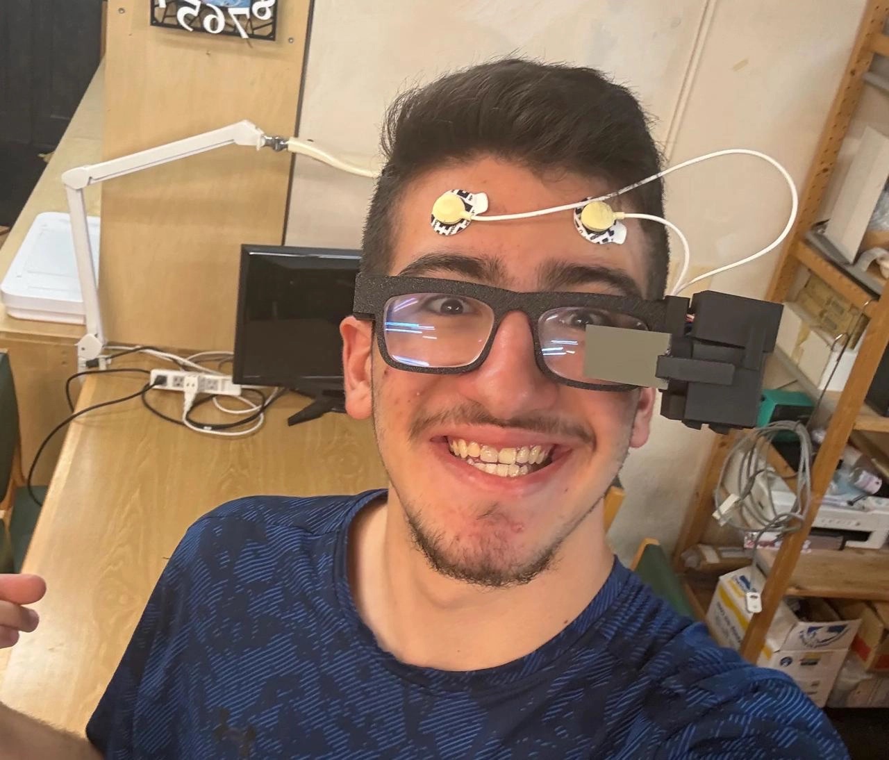
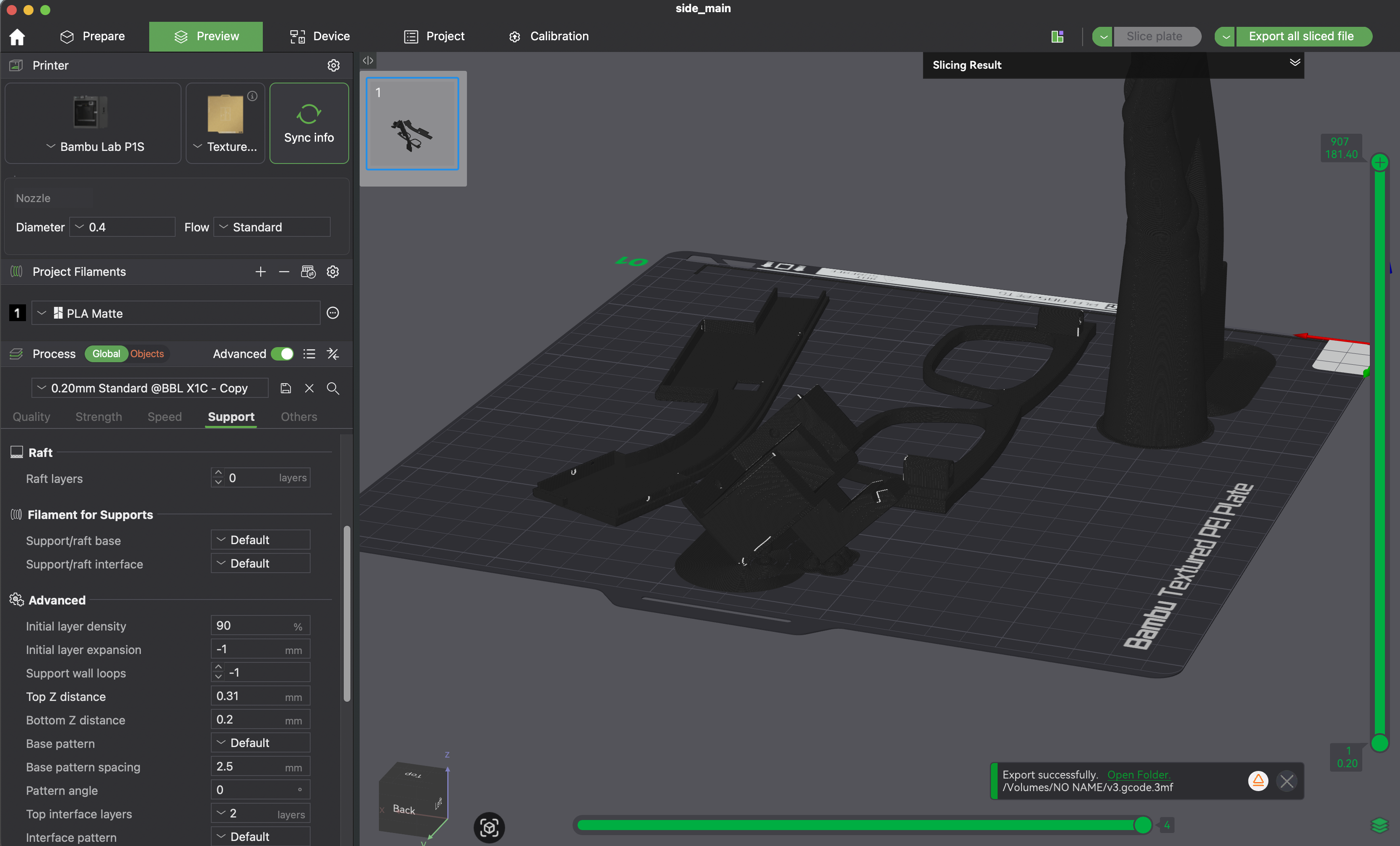
18: Final Integration and Scope Lock
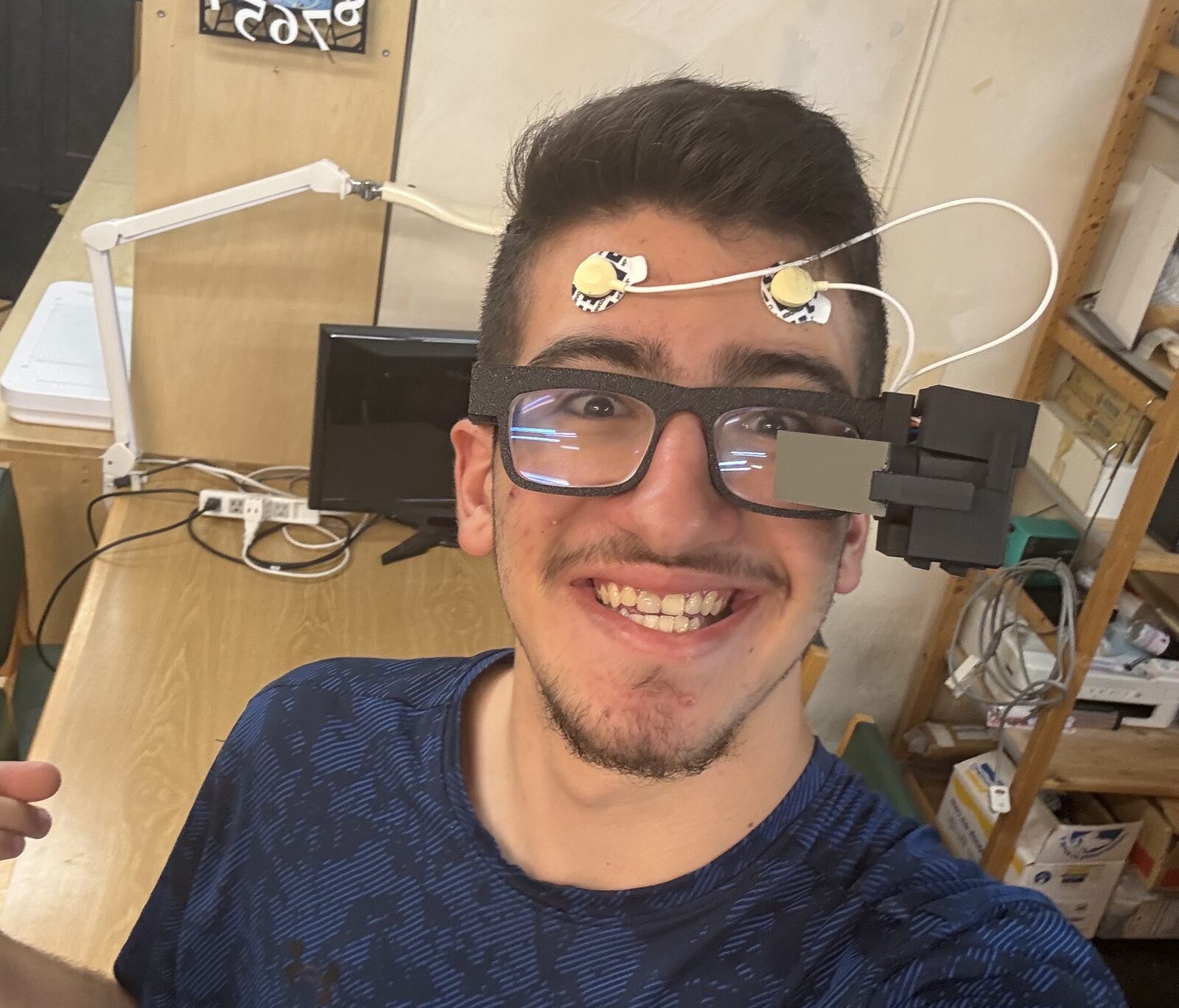
As the project moved into final integration, I tested the side-mounted AR display assembly on the glasses frame and checked the combined wearable fit with the forehead electrodes in place.
The last stretch was the presentation work: the BOM, risks, and evaluation plan from Week 18, the dissemination plan and Fab license from Week 19, redesigning the website, and the final slide and one-minute video.
The project is not ending as "I built a perfect brain-controlled AR headset." That would be dishonest. It is ending as a real wearable AR + biopotential prototype with a clear signal path, a tested dashboard and Display Studio, a LIF-SNN pipeline that runs end to end on the board, and a very clear list of what has to improve next.
Development Summary
The project moved through its spirals roughly like this:
- first, the wearable frame, logo, and AR display direction;
- then the microcontroller, display, camera, and early EEG experiments;
- then the Spiral 0 EEG board and the interface loop around it;
- then the physical integration with custom packaging and the ADS1292 front-end;
- then the software spiral: the MicroPython runtime, the LIF-SNN, the dashboard, and Display Studio;
- then connecting the glasses to Poke through a hosted MCP relay.
The biggest technical lesson is that the interface can get ahead of the signal very easily. The dashboard can look polished, the model can output labels, and the display can react, but none of that matters if the physical signal is not clean enough. So the next real work is not making the model bigger. It is improving electrode contact, reference behavior, cable strain relief, power isolation, and the recording dataset.
NeuroAR is released under the Fab license: (c) Yusuf Kusibati, June 2026.