
Week 11
Week 11: Networking and Communications
I documented networking through ESP-NOW group work and built a networked music-player direction using the XIAO, a receiver board, and the broken-OLED lessons.
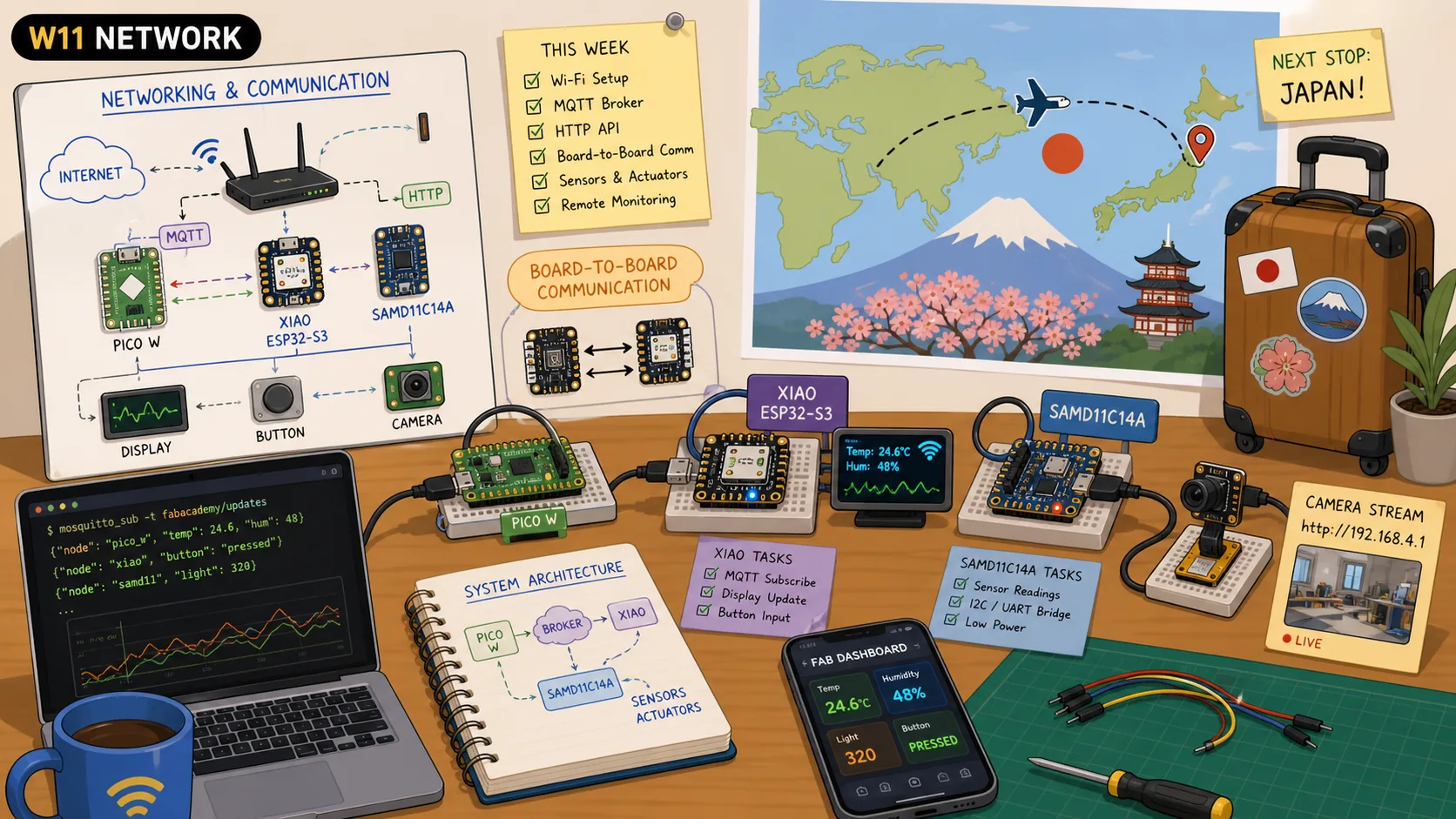
This week was a bit messy as I was in Saudi Arabia initially and then moved to Japan. Lots of change, especially the jet lag. It was insane.
Anyways, on the way to Japan and while the plane was departing from Qatar, I saw missiles flying at a distance, but thankfully made it safely. Honestly, I still can't believe I am in Japan, very grateful for this oppurtunity :D
This week's assignment was completed over the subsequent weeks, primarily I used 2 concept boards that I will be using aspects of in my final project: a "capacitive" touch area, speaker, display, and a button.
Jump to this week's checklist
Group Assignment: Sending a Message Between Two Projects
By the time I landed in Yokohama, Fumiko, my FabLab Kannai lab partner, had already finished our group assignment, so my contribution was mostly reviewing her work and making sure I understood the protocol she chose.
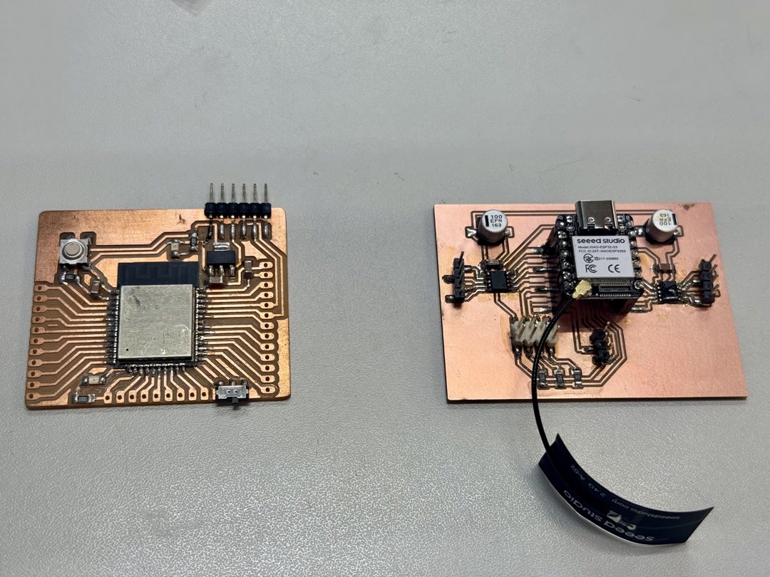
The setup is a custom XIAO ESP32-S3 board (sender) talking to a Barduino / OLIMEX ESP32-DevKit-LiPo (receiver). Press the switch on the XIAO and an LED on the Barduino lights up.
The two boards are not on the same Wi-Fi network, there is no router between them, and there are no wires running between them. The message moves over the air using ESP-NOW, Espressif's lightweight peer-to-peer protocol that lives below the IP stack.
How ESP-NOW works in this setup?
ESP-NOW works like sending a letter to a known address. There is no router and no pairing. The sender knows the receiver's MAC address, drops a packet on the radio, and the receiver (which has registered a callback in advance) gets handed the bytes whenever one shows up addressed to it.
The properties from her notes that mattered for our switch → LED case:
| Aspect | Detail |
|---|---|
| Addressing | 6-byte MAC address of the receiver |
| Payload | Up to 250 bytes per packet |
| Latency | Under 10 ms |
| Range | ~200 m in open space |
| Encryption | Optional AES-128 |
How the work was actually done?
The process had three steps:
Stage 1, Unit test each board on its own:
Before any networking, flash a sketch that just prints to serial every second on the XIAO, and a sketch that blinks the LED on pin 13 of the Barduino. The point is to eliminate hardware faults early.
Stage 2, discover MAC addresses:
ESP-NOW needs the receiver's MAC baked into the sender's firmware, and there is no automatic discovery. So each board ran a sketch that prints WiFi.macAddress() to serial:
XIAO MAC:     10:20:BA:03:93:BC
Barduino MAC: C8:2B:96:9F:F7:08
Stage 3, write the sender and receiver:
Two sketches in the same PlatformIO project, two [env] blocks in platformio.ini targeting the two different boards. Each sketch only compiles its own .cpp file via build_src_filter, so a single repo holds both halves of the link.
Reading the sender (XIAO)
Going through the code, the sender does four things:
- Reads the switch on pin D4 with a 30 ms software debounce.
- On a confirmed state change, fills in a
Messagestruct withpressed(bool) andcounter(uint32_t). - Calls
esp_now_send(receiverMac, ...)to push the bytes to the receiver. - Has a send-callback (
onSent) that fires when the radio reports success or failure.
What I noticed reading this is the choice to use a fixed-size struct instead of a string like "PRESSED" / "RELEASED". Both sides declare the same struct:
typedef struct {
  bool pressed;
  uint32_t counter;
} Message;
The sender does esp_now_send(mac, (uint8_t *)&msg, sizeof(msg)) and the receiver does memcpy(&msg, incomingData, sizeof(msg)). The message itself isn't human-readable rather a fixed-sized binary struct.
The counter field is a useful detail too; it gives the receiver a way to tell apart a new state change from a duplicate or re-ordered packet.
Reading the receiver (Barduino)
The receiver is even simpler. At setup, it registers a callback:
esp_now_register_recv_cb(onReceive);
…and that's basically it. From then on, every time a frame arrives addressed to its MAC, the ESP-NOW driver calls onReceive with the payload. The callback memcpys the bytes back into a Message struct and stores pressed in a volatile bool. The main loop just reads that bool and writes the LED.
The sender knows exactly who it is talking to (the receiver's MAC is hard-coded), but the receiver does not know or care who is talking to it. The receiver just listens for "anything addressed to me on the ESP-NOW protocol" and fires the callback.
Worth noting because it tripped Fumiko: the OLIMEX Barduino does not auto-reset into the bootloader the way the XIAO does. To upload firmware you have to physically toggle a "Programming" mode switch and reset, then toggle back to "Execution" mode and reset before opening the serial monitor.
Learnings from Global Session
Coming into this week, my mental model of "networking" revolved a lot around Wi-Fi. You join a network, you get an IP, you call an API, and I have set up my own home network back in Saudi with a NAS.
Networking is just any time two pieces of hardware need to agree on a way to move bits, and depending on how far apart they are and what they need to send, "the way" can be wildly different.
This week's global session was led by Henk Buursen (from Waag FutureLab), Eric Pan (the founder of Seeed Studio, the Shenzhen open hardware company behind the XIAO boards I have been soldering), Luc Hanneuse from an AgriLab, and Saheen Palayi from FabLab Kerela.
The seven layers of communication
The seven layers of the OSI (Open Systems Interconnection) model from the bottom up are: the physical layer is the actual electrons or photons on the wire, the data link layer is MAC addressing and Ethernet frames, the network layer is IP and routing, the transport layer is TCP and UDP, the session layer is connection state, the presentation layer is encryption (TLS) and character encoding, and the application layer is where HTTP, MQTT, and CoAP actually live.
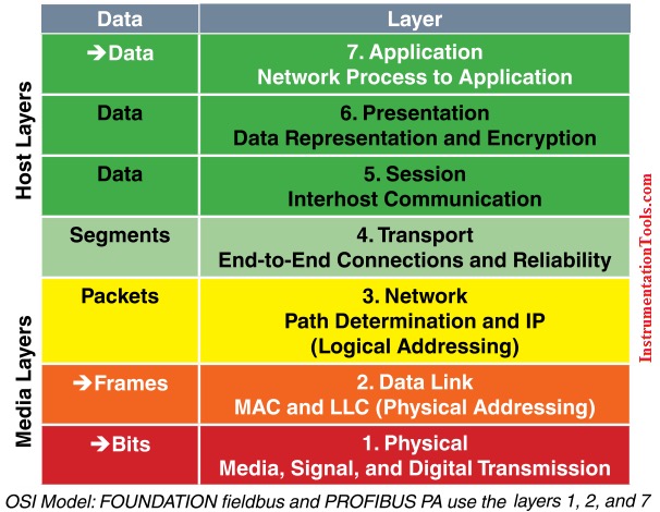
When something breaks, knowing which layer it's breaking at is a good start to diagnose the isse. A bad solder joint is a layer 1 problem. A wrong URL path is layer 7.
Asynchronous Serial and MCU Serial Peripherals
UART is dead simple. Two wires (TX and RX), one common ground, and a baud rate both sides agree on. The address is purely physical: whoever is wired up at the other end.
USART is the universal version that can also speak synchronously if you wire a clock. SERCOM is the configurable serial controller on Atmel SAM chips that can be configured as UART, SPI, or I2C in software.
PIO, or Programmable I/O, allows you to create additional hardware interfaces or even entirely new types of interface. It was developed initially for the RP2040, using small dedicated processors on the chip that handle signal timing independently from the main CPU, so you can implement custom protocols without slowing down the rest of your code.
Bit banging refers to any implementation of serial communication directly driven by software. Instead of using a dedicated peripheral, the software reads and writes the input and output pins and handles timing itself. It is the fallback when none of the other options work on the pin you need.
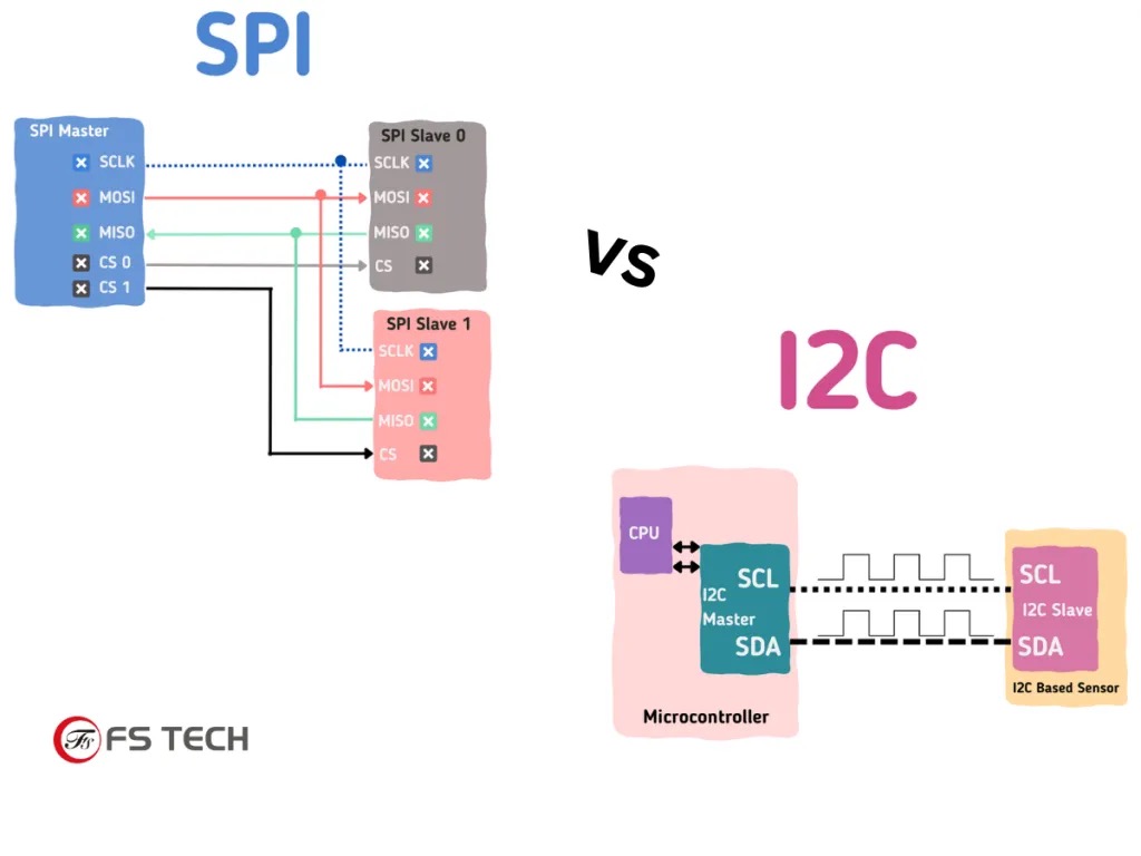
Synchronous serial: I2C, SPI, and the bus model
Synchronous serial means the devices share a clock line. The clock tells the receiver when to read each bit, so the timing comes from the signal itself instead of only from an agreed baud rate like UART.
I2C uses two wires: SCL for clock and SDA for data. Many devices can share those same two wires because every device has an address. The controller sends the address first, then only the matching device responds. I2C is useful for slow peripherals like sensors and OLED displays when I want to save pins.
SPI uses a clock, a data line from controller to peripheral, a data line back, and a chip-select line for each device. Instead of sending an address in the message, the controller selects a device by pulling its chip-select pin low. SPI uses more pins, but it is faster and better for data-heavy devices like SD cards, displays, fast IMUs, and ADCs.
So the rule is simple: I2C is better for many slow devices with few wires. SPI is better when I need speed or continuous data.
Other wired protocols
USB carries an HID (Human Interface Device) profile that lets a microcontroller emulate a keyboard, mouse, or joystick, which is how a lot of projects send typed output without needing a screen.
The TinyUSB stack handles all of this on capable chips, including USB MIDI for music projects.
Ethernet comes through chips like the WIZnet W5500 (the WIZ850IO module is the typical breakout) which handle the full TCP/IP stack on-chip and present an SPI interface to the microcontroller, so the MCU only sees application data.
CAN (Controller Area Network) is the differential bus that cars and tractors run on, and increasingly machines like 3D printers too, with built-in priority-based arbitration so the highest-priority message wins automatically when there is a collision.
LIN is the slower, cheaper, single-ended cousin used for low-speed automotive accessories.
MODBUS is the industrial control protocol layered on top of RS-485 in a lot of factory equipment.
DMX is what stage lighting runs on. EtherCAT is the high-end industrial protocol that runs over standard Ethernet hardware but achieves microsecond-level synchronisation across many slaves on the same wire.
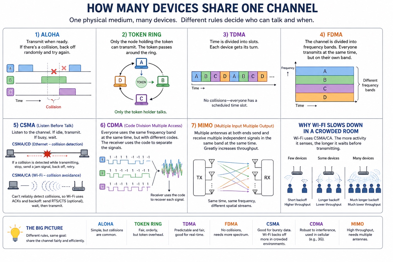
Sharing the channel
Whenever many devices share a single physical medium, there has to be a rule for who gets to talk when. The main approaches:
- ALOHA (transmit when ready, back off on collision),
- Token Ring (only the node holding the token can transmit),
- TDMA (everyone gets a time slot),
- FDMA (everyone gets a frequency band),
- CSMA which means listen-before-talk (Ethernet uses CSMA/CD with collision detection, Wi-Fi uses CSMA/CA with collision avoidance because you can't reliably detect collisions in a wireless medium),
- CDMA (spread spectrum, different transmitters use orthogonal codes to share the same band),
- and MIMO (multiple antennas, multiple signals in the same band at the same time).
This is why Wi-Fi slows down in a crowded room: CSMA/CA backs off harder when it senses more activity.
The physical limit on wireless
Once you go wireless you run into a physics constraint that does not exist on a wire. The Shannon-Hartley theorem defines the maximum rate (C) at which information can be transmitted over a communications channel of a specified bandwidth (B) in the presence of noise, known as the channel capacity, z, and S over N is the signal-to-noise ratio.
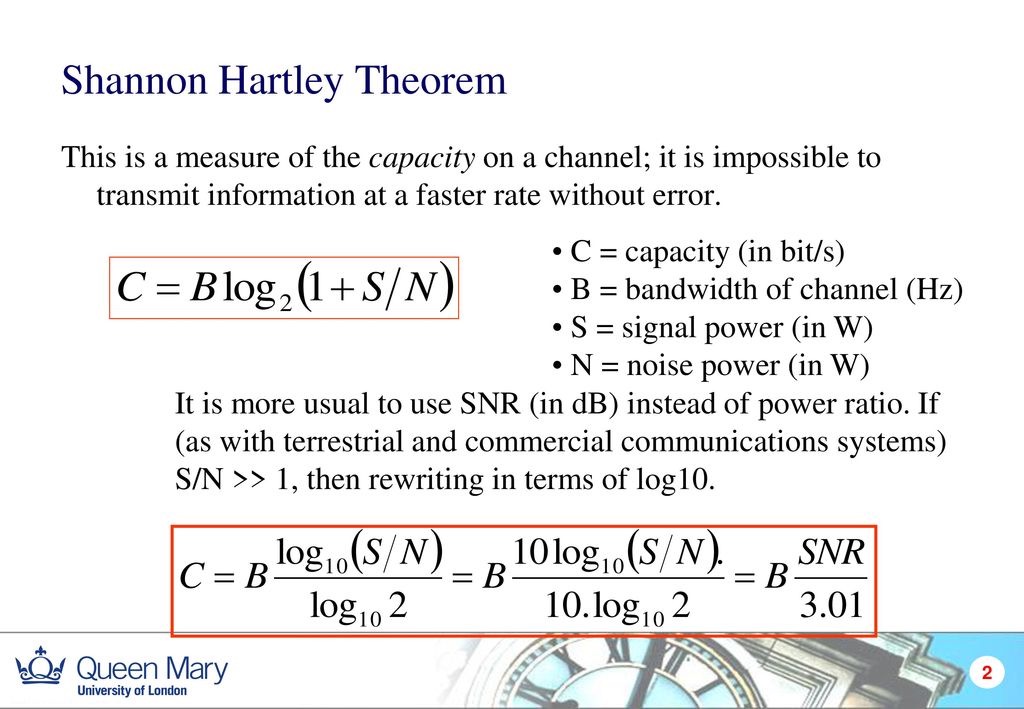
That is a hard ceiling on how much information you can push through a given band at a given SNR. Every wireless decision (range, power, throughput, antenna size, modulation choice) lives inside that equation.
Modulation schemes are the menu of ways to encode bits onto a physical signal:
- OOK (on-off keying, the simplest),
- FSK (two tones, classic modems),
- BPSK (a 180-degree phase flip per bit),
- QAM (combined amplitude and phase, the workhorse of high-throughput links),
- OFDM (orthogonal frequency-division, what Wi-Fi and LTE actually use),
- FHSS (frequency hopping, classic Bluetooth),
- DSSS (direct-sequence spread spectrum, 802.11b),
- and UWB (impulse-based ultra-wideband, used for indoor positioning).
The tradeoff is roughly that fancier modulations get more bits per hertz at the cost of needing a better SNR.
ISM bands and the Wi-Fi/BLE family
The ISM bands (industrial, scientific, medical) are the slices of the spectrum bands reserved for unlicensed use under FCC Part 15 in the US and equivalent regulations elsewhere:
- 13.56 MHz: NFC and HF RFID. Very short range, used for tags, cards, and phone tap interactions.
- 433 MHz: sub-GHz radio band used by simple remote controls and low-data sensors. Longer range than 2.4 GHz, but low bandwidth.
- 868 MHz: regional sub-GHz ISM band used mostly in Europe for low-power long-range devices like LoRa.
- 915 MHz: regional sub-GHz ISM band used in places like the US and Japan for low-power long-range devices like LoRa.
- 2.4 GHz: the crowded global band used by Wi-Fi, Bluetooth, BLE, Zigbee, ESP-NOW, and many hobby radio modules. Convenient, but lots of devices compete for it.
- 5 GHz / 5.8 GHz: used mainly for faster Wi-Fi and some video/radio links. Higher bandwidth, but shorter range and worse wall penetration than 2.4 GHz.
The XIAO ESP32-S3 I am using has Espressif radio modules built in that handle Wi-Fi (802.11 b/g/n) and BLE on the same chip, plus an 802.11 Long Range mode that trades throughput for distance.
The same chip can also speak ESP-NOW, which is Espressif's broadcast-style protocol that does not need a router and is much faster than going through Wi-Fi for board-to-board comms.
BLE itself is the low-power version of Bluetooth, sharing the 2.4 GHz band with classic Bluetooth. GATT (Generic Attribute Profile) defines services and characteristics, GAP (Generic Access Profile) handles discovery and connection, and every service has a UUID.
The Nordic nRF Toolbox app and the Linux BlueZ stack are the standard tools for poking BLE peripherals from a phone or laptop.
LoRa, nRF, NFC, and Zigbee
The main decision with wireless protocols is range, power, and how much data I need to move.
LoRa is for long range and low power, but only small packets. It is good for outdoor sensors or remote status messages, not for audio, video, or fast interaction.
nRF radios are useful when I want a simpler radio link without full Wi-Fi. Some are simple 2.4 GHz radios, while the nRF52 family can also handle Bluetooth-style work.
NFC and RFID are short-range communication, not sensing. They are for tags, cards, and tap interactions.
Zigbee is a low-power mesh protocol used in smart home devices. It is slower than Wi-Fi, but better for small battery devices that only send simple state changes.
How the internet actually works
The internet is a stack of agreements. The device first connects to a local network through Wi-Fi or Ethernet. The router gives it an IP address, usually with DHCP. DNS turns a human name into an IP address.
After that, data is split into packets. IP handles addressing and routing, so packets can move through routers toward the destination. Packets do not all need to take the same path.
TCP and UDP sit above IP. TCP checks that data arrives in order and resends missing parts, which is why it is used for webpages and files. UDP skips most of that reliability work, so it is useful when low delay matters more, like video calls or real-time control.
HTTP is the language the browser and server use for web requests. HTTPS is the same idea with encryption added through TLS. When I open a webpage, the browser uses DNS to find the server, TCP/TLS to make the connection, then HTTP to request the page.
Error detection and correction
When bits get flipped on a noisy wire or radio link, protocols usually either detect the error and retry, or add enough extra information to correct some errors without retrying. Parity, checksums, and CRCs are used for detection. Hamming codes and Reed-Solomon codes are used for correction. The practical difference is simple: if the sender can retry, detection is usually enough. If retrying is expensive or impossible, correction matters more.
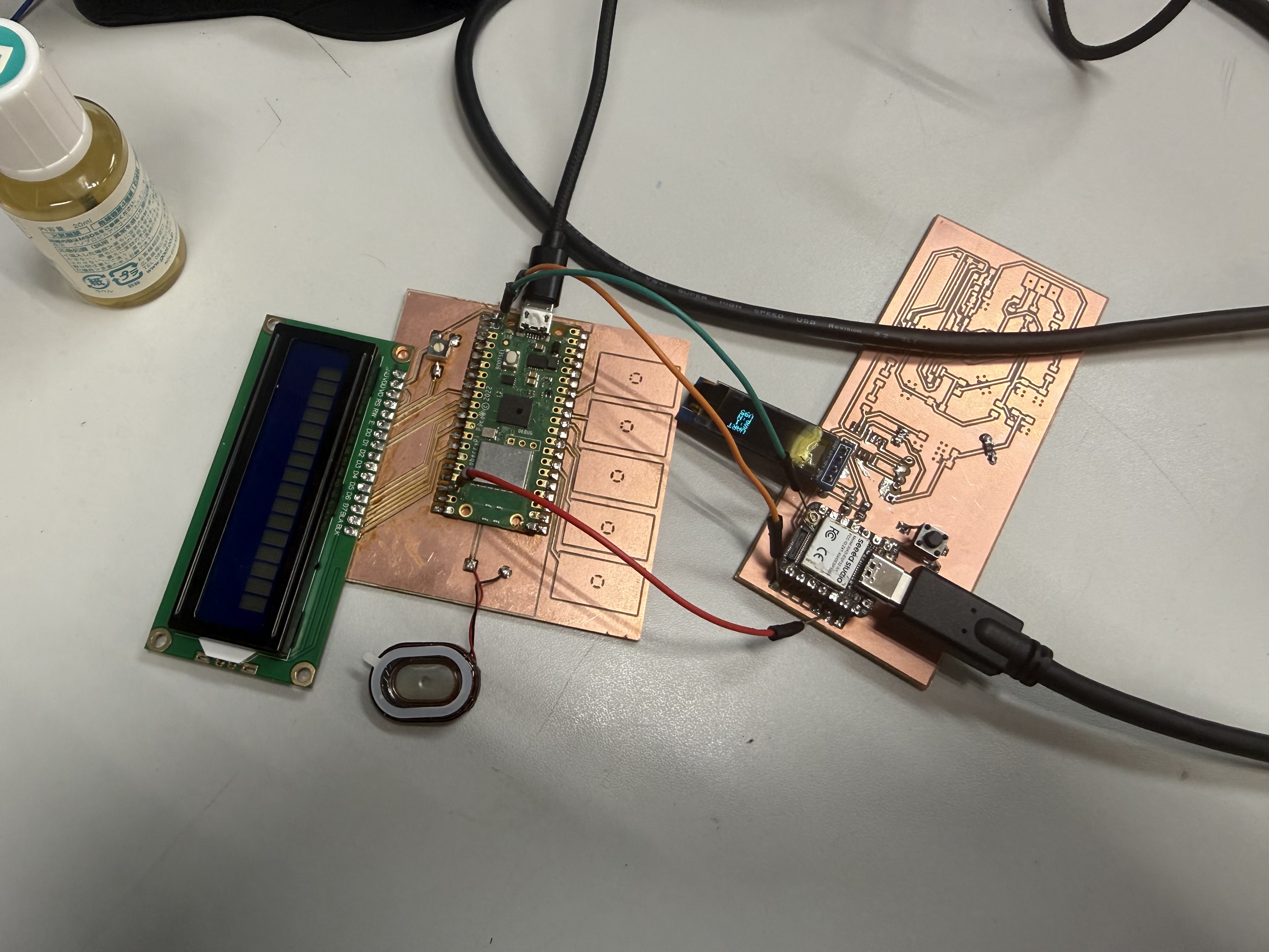
Building a Networked Music Player
The controller board is the XIAO ESP32S3 board with the OLED display and SW1 button. The sound board is the Pico W board with the step-response pads and speaker. I ignored the other final-project board connections for this assignment.
The two communication methods I tried and used were:
- UART with jumper wires
- WiFi using HTTP requests
The application is a networked music player:
- Short press on the XIAO button changes the selected song.
- Long press sends a play command to the Pico W.
- The Pico W plays the selected WAV file.
- The step-response pads on the Pico W control volume.
- The Pico W sends volume and playback status back to the XIAO.
- The XIAO OLED shows the selected song, playback state, and volume.

Pin Map
For both boards I am only using a small subset of pins. The OLED, button, and UART pins on the XIAO; the speaker, step-response pads, and UART pins on the Pico W.
XIAO ESP32-S3 controller board:
| Function | Pin |
|---|---|
| OLED SDA | D4 / GPIO5 |
| OLED SCL | D5 / GPIO6 |
| SW1 button | D1 / GPIO2, active low |
| UART TX | D6 / GPIO43 |
| UART RX | D7 / GPIO44 |
| OLED address | 0x3 |
Pico W music board:
| Function | Pin |
|---|---|
| UART0 TX | GP0 |
| UART0 RX | GP1 |
| Step-response pads | GP28, GP27, GP26, GP22, GP21 |
| Speaker PWM audio | GP20 |
Both boards are 3.3 V logic, so for the UART test I just connected signal jumpers and a common GND with both boards powered from USB. No level shifter needed.
These boards had a bigger purpose for my final project that you can find in my project development log.
A Note On My Broken OLED
My OLED is mostly toast on the left side. Only the right edge is reliable, so all my XIAO sketches start drawing at x = 96 on the 128-pixel-wide screen:
#define OLED_SAFE_X 96
The display ends up looking like this:
UART
S:1
P:Y
V73
Where S:1 is the selected song, P:Y is "Pico is currently playing", and V73 is volume = 73. Tiny, but enough to see what the system is doing.
OLED Status Alphabet
I built a small status alphabet so I could debug each step of the protocol from the OLED. The reason it has so many states (rather than just "playing / not playing") was something I learned the hard way during testing, more on that in the debugging section below.
| OLED text | Meaning |
|---|---|
S:1, S:2, S:3 |
selected song number |
P:N |
Pico is idle or the song already finished |
P:Q |
XIAO sent PLAY and is waiting for the Pico to acknowledge |
P:Y |
Pico confirmed the WAV is playing |
P:E |
Pico received PLAY but failed to start the WAV |
P:? |
XIAO never received an acknowledgement for the latest play command |
V10 to V100 |
volume reported by the Pico W |
Audio Files
All Pico sketches share the same WAV files in LittleFS. Since they are identical for every test, I keep them in a single folder at the project root and point each Pico's platformio.ini at it:
[platformio]
data_dir = ../../audio
The three WAV files are:
| Display name | File in LittleFS |
|---|---|
| Fur Elise | fur_elise.wav |
| Greensleeves | greensleeves.wav |
| Entertainer | the_entertainer.wav |
All three are 8-second, 8 kHz, mono, unsigned 8-bit PCM WAV files. I picked that format because the Pico W can stream it from LittleFS with very simple code (read a sample, scale by volume, write to PWM, repeat). The originals are public-domain or CC-licensed clips downloaded from Wikimedia Commons (links at the bottom of this page).
Upload vs uploadfs
PlatformIO has two upload commands that matter for this week:
pio run -t uploadwrites the compiled firmware to the board.pio run -t uploadfswrites the contents ofdata_dirinto the board's LittleFS partition.
For each Pico sketch I need to run uploadfs whenever:
- I'm testing the sketch for the first time
- I add, rename, or replace a WAV file
- the OLED shows
P:Eand the Pico's serial monitor says a WAV file is missing
The XIAO sketches don't need uploadfs because they don't read anything from LittleFS, just text from UART or HTTP.
The Shared WAV Player
Both Pico sketches use the same common/pico_wav_player.h file, which handles all of the audio. When the Pico boots, PicoWavPlayer::begin() mounts LittleFS and prints whether each of the three expected WAVs was found. The parser checks for the usual RIFF / WAVE / fmt / data chunks, supports 8-bit or 16-bit PCM, and 1 or 2 channels.
During playback, PicoWavPlayer::service(volume) reads samples at the right sample rate, centers each sample around 128, scales it by the current volume, and writes it to PWM:
int centered = (int)sample - 128;
int scaled = 128 + (centered * (int)volume) / 100;
analogWrite(audioPin, constrain(scaled, 0, 255));
PWM is at 62.5 kHz with a 0-255 range. It is simple, it works, and it sounds rough — I will get to the audio quality section near the end.
Test 1: UART With Jumper Wires
UART made the most sense to start with because it is the most direct protocol I could think of. Two boards, two wires (plus ground), text travels in both directions, no addressing, no discovery, no network stack. The "who am I talking to" question is answered by "whoever is on the other end of this jumper."
UART Wiring
| XIAO ESP32-S3 | Pico W | Why |
|---|---|---|
| D6 / TX / GPIO43 | GP1 / UART0 RX | XIAO sends commands to Pico |
| D7 / RX / GPIO44 | GP0 / UART0 TX | Pico sends status back to XIAO |
| GND | GND | shared reference |
The TX of one board goes to the RX of the other in both directions. If you wire TX-to-TX, nothing happens (and that took me about 10 minutes to realize that I switched them at the start, lol).
XIAO Side (Controller)
The XIAO sketch starts a hardware UART on Serial1 using its D6/D7 pins:
Serial1.begin(115200, SERIAL_8N1, UART_RX_PIN, UART_TX_PIN);
On a long press, the XIAO increments a sequence number and sends one line of text:
PLAY,song,seq,name
For example: PLAY,1,4,Greensleeves.
It also reads back lines from the Pico and parses them as status packets:
STATUS,volume,state,song,statusSeq,ackSeq
For example: STATUS,73,1,1,28,4.
The reason both packets carry sequence numbers is because of one of the bugs I'll cover below.
The button code itself is fairly standard: it reads SW1 with INPUT_PULLUP, debounces over 25 ms, treats anything under 700 ms as a short press (cycle song), and anything over 700 ms as a long press (send play). The OLED is redrawn every 100 ms with the latest known state.
Pico Side (Music Player)
On the Pico, the UART pins are GP0 (TX) and GP1 (RX), and Serial1 exposes them:
Serial1.setTX(0);
Serial1.setRX(1);
Serial1.begin(115200);
The Pico's main loop does three things: (1) services UART so it picks up incoming PLAY commands, (2) services the WAV player and reads the step-response pads to update audio output and volume, and (3) sends a status packet every 200 ms with the current volume, playback state, current song, and last play sequence it received.
When a PLAY command arrives with a new sequence number, the Pico calls startSong(song, seq), which loads the right WAV from LittleFS and calls PicoWavPlayer::start(). If the WAV starts cleanly, playerState becomes 1 and the XIAO will see P:Y. If the WAV fails to open, playerState becomes 2, and the XIAO will see P:E.
Step-Response Pad Volume
The Pico has five pads (GP28, GP27, GP26, GP22, GP21) that I use as a left-to-right volume strip. The function stepTime() measures each pad by:
- Driving it low.
- Briefly delaying.
- Switching the pin to input with a pull-up.
- Counting how many loop iterations it takes to read high.
A finger on the pad changes the capacitance, which slows down the rise time, which gives a bigger count. Then readVolume() picks the pad with the largest delta from its no-touch baseline and maps that pad position to a volume value:
left pad   -> lower volume
right pad  -> higher volume
no touch   -> hold last volume
Volume starts at V40. If no pad is touched strongly enough, the function just returns the current volume, so the level stays where I left it instead of decaying back to zero. This sounds obvious in hindsight but it took a debugging round to get right (see below).
Putting It All Together
Once the wiring was solid and both sketches were loaded, the test was satisfying:
- Connected
GND-GND,XIAO D6 -> Pico GP1, andXIAO D7 -> Pico GP0. - Uploaded the Pico sketch and ran
uploadfsso the WAV files were in LittleFS. - Uploaded the XIAO sketch.
- Short-pressed the button to cycle songs (
S:1->S:2->S:3). - Long-pressed to send
PLAY. OLED wentP:QthenP:Y, and music came out of the Pico. - Slid my finger across the Pico's pads. The
Vvalue on the XIAO OLED tracked the position.
The serial log on both sides showed the actual text moving across the wires, which was probably the most rewarding part: I could literally see PLAY,1,5,Greensleeves being sent by one board and STATUS,73,1,1,28,5 coming back from the other.
Test 2: WiFi With HTTP
For the wireless version I went with HTTP. The idea was to make the XIAO act as a small web server and the Pico W act as an HTTP client that polls the XIAO for commands and posts status back. Same controls as the UART version, totally different transport underneath.
Both sketches use the lab Wi-Fi:
const char *WIFI_SSID = "fablabkannai";
const char *WIFI_PASS = "I won't put the password here";
After uploading the XIAO server, you open the XIAO serial monitor and copy whatever IP it prints:
XIAO IP: 192.168.x.x
That IP gets pasted into the Pico's HTTP client:
const char *XIAO_HOST = "192.168.x.x";
That little manual step (copy IP, paste IP, re-upload Pico) is the hidden cost of HTTP for me. With UART you just plug the wires in and go.
XIAO Side (HTTP Server)
The XIAO sets up a WebServer on port 80 with three routes:
| Route | What it does |
|---|---|
/ |
Returns a plain-text dump of the current state. Handy for browsing from a laptop while debugging. |
/cmd |
Returns the current selected song and play sequence so the Pico can poll it. |
/status |
Receives status from the Pico via query parameters. |
The /cmd response is a tiny CSV line:
selectedSong,playSeq,songName
And /status is just a GET request with query params, which the XIAO reads with server.arg():
/status?vol=73&state=1&playing=1&song=1&seq=28&ack=4&mac=...
The same acknowledgement rule from UART applies here: the XIAO only clears P:Q when the Pico's ack value matches the latest playSeq.
One difference is the HTTP version has a longer ack-wait timeout:
#define HTTP_ACK_WAIT_MS 7000
That is because the lab Wi-Fi plus the Pico's polling interval can easily delay the ack by a couple of seconds. With UART, packets are basically instant. With HTTP, "instant" is a bit slower.
Pico Side (HTTP Client)
The Pico has a small helper, httpGet(), that opens a WiFiClient, fires off a GET request, reads the response, and returns the body (everything after the first blank line):
client.print(String("GET ") + path + " HTTP/1.1\r\n" +
             "Host: " + XIAO_HOST + "\r\n" +
             "Connection: close\r\n\r\n");
The Pico's main loop polls /cmd every 300 ms and posts /status every 250 ms:
if (millis() - lastCommandMs > 300) pollCommand();
if (millis() - lastStatusMs > 250) sendStatus();
If /cmd returns a playSeq higher than what the Pico has seen before, it knows a new long press happened on the XIAO and it fires off the matching WAV.
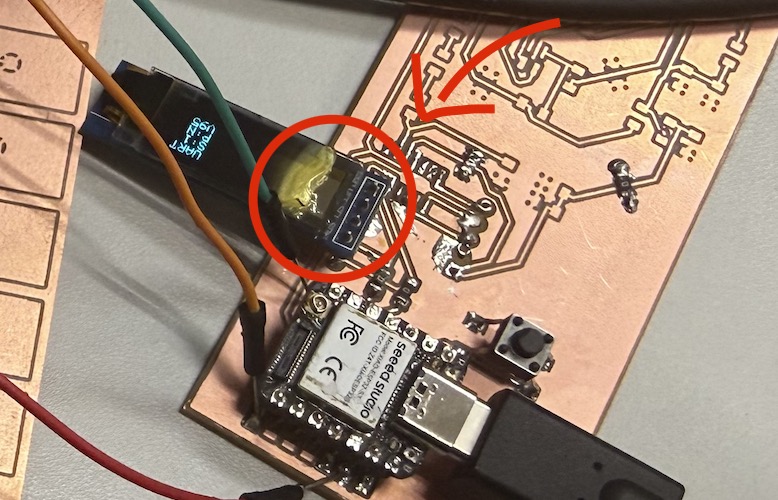
What Actually Happened (and the Antenna)
Big surprise on the first attempt: it did not work at all. The XIAO was stuck on the WIFI screen for what felt like forever, never moving on to HTTP. It was not joining the network.
The XIAO ESP32-S3's antenna was not connected. The XIAO ESP32-S3 ships with a separate u.FL antenna, and if you forget to plug it in, the Wi-Fi can sometimes scan and even connect to nearby networks but it is incredibly flaky.
After I attached the antenna, it joined the lab network on the first try and stayed connected.
After the antenna fix, the rest of the test went the same way as the UART one: short press to cycle songs, long press to play, finger on the pads to change volume.
The one observable difference: every now and then the OLED briefly flashed P:? before settling on P:Y. That meant the play command actually reached the Pico but the acknowledgement back to the XIAO did not show up before the timeout. With UART I never saw P:?. With HTTP it was a regular occurrence on a busy network.
Debugging Stories
I'll walk through each problem in the order I hit them, because the fix for each one taught me something I want to remember for future networking projects.
"P:N forever" Boolean Status Was Not Enough
The first bug: I would long-press the button, the music would actually play, but the OLED never moved off P:N. Or sometimes it would briefly say playing, and sometimes it would not. It was inconsistent in a way that made me think the UART link itself was bad.
It was not. The problem was that the Pico was reporting a single playing boolean, and the XIAO was just displaying it. So a missed command, a missing LittleFS upload, and a successful playback that ended quickly all looked the same: P:N.
Fix: I changed the Pico's status from a boolean to an explicit playerState integer:
0= idle1= playing2= error (received command but couldn't open the WAV)
And the XIAO turned that into the four-character status alphabet I described earlier (P:N, P:Q, P:Y, P:E, P:?). Suddenly each failure mode looked different on the screen, and I could actually tell what was going wrong without plugging in a serial monitor.
"P:Q for a Moment Then Back to P:N" The Status Race
Once P:Q existed, a new bug showed up: after a long press, the OLED would briefly say P:Q (good, command sent), then flip back to P:N (huh?), and only some time later become P:Y.
What was happening: the Pico sends a status packet every 200 ms. So in the window between "command arrived at the Pico" and "Pico actually starts playing the WAV", an idle status was getting through, and the XIAO was happily displaying that idle state on top of its own P:Q.
Fix: I added a playSeq counter to every command and an ackSeq to every status packet. A status from the Pico is only allowed to override the P:Q state if its ackSeq matches the XIAO's current playSeq. Otherwise, the XIAO knows it is an old status packet from before the command and ignores the playback fields.
This is the bug whose fix I think I will keep for any future networked project. Sequence numbers are cheap, and they let you tell the difference between "the answer to my latest question" and "the answer to whatever the other side felt like saying just now."
"Volume Falls Back to V11 When I Let Go"
This one was on the Pico side, not networking, but the assignment is about how the XIAO's view of the system feels. The volume number on the OLED kept dropping back to around V11 or V12 whenever I let go of the pads.
What was happening: my "best touched pad" logic was always picking some pad as the strongest, even when nothing was being touched. So as soon as I lifted my finger, the strongest "touch" was just noise on the leftmost pad, which mapped to a low volume.
Fix: I added a touch-strength threshold (TOUCH_ACTIVE_DELTA = 100). If no pad's delta beats that threshold, readVolume() just returns the current volume. So now the volume only updates when there is actual touch, and when I let go it freezes at whatever level I last set.
Pad Direction
Related: I wanted left-to-right movement to mean "louder". The first version I wrote had the pads reversed and felt backwards under my hand. The current code assumes GP28, GP27, GP26, GP22, GP21 is the left-to-right order. If the physical board ever ends up reversed in a future revision, all I have to do is reverse that array in the Pico sketches.
The Antenna
Already covered in the HTTP section, but worth saying again because I would never have guessed it on my own: always check the XIAO ESP32-S3 antenna is plugged in before debugging Wi-Fi code.
Audio Quality
The audio is rough and I want to be honest about that. The signal chain is:
LittleFS WAV file
  -> 8-bit sample
    -> volume scaling
      -> PWM duty cycle on GP20
        -> directly to a small speaker
That works for proving "the protocol got the play command across", but it is not really hi-fi. A few reasons it sounds rough:
- The files are 8 kHz, 8-bit to keep them small enough to fit in LittleFS.
- PWM creates high-frequency switching noise on top of the audio.
- A speaker really wants more current than a single GPIO pin can drive cleanly.
- There is no low-pass filter, so the PWM carrier reaches the speaker.
- There is no amplifier, so it ends up quiet and distorted at the same time.
If I were doing this for real (and I might, for the final project), the upgrades I would apply roughly in order:
| Approach | What it adds |
|---|---|
| Add an RC low-pass filter on GP20 | smooths the PWM into a more analog-looking waveform, less switching noise |
| Add a small audio amp board | louder output, less strain on the GPIO pin |
| Replace PWM with an I2S DAC + amp (e.g. MAX98357A) | actual digital audio path designed for music playback |
For this week I deliberately stopped at "PWM straight into a speaker" because the assignment is about the communication, not the audio. But it is in the back of my head as the next thing to fix when I come back to this for the final project.
Original Design and Code Files
- UART link (XIAO + Pico) —
01_uart_link.zip - WiFi/HTTP link (XIAO server + Pico client) —
02_wifi_http.zip - Shared audio folder (LittleFS WAV files) —
audio.zip
Audio Sources
The three audio clips are converted from Wikimedia Commons files:
- Fur Elise, performed by Sebion7125, CC BY-SA 3.0: https://commons.wikimedia.org/wiki/File:Fur_Elise.ogg
- Greensleeves, by CambridgeBayWeather, CC BY 3.0 / GFDL: https://commons.wikimedia.org/wiki/File:Greensleeves.ogg
- The Entertainer, performed by IE at English Wikipedia, public domain: https://commons.wikimedia.org/wiki/File:The_Entertainer_-_Scott_Joplin.ogg
I converted each one to 8 seconds, 8 kHz, mono, unsigned 8-bit PCM WAV with ffmpeg before uploading to LittleFS.
This week's checklist
- Linked to the group assignment page
- Documented your project and what you have learned from implementing networking and/or communication protocols.
- Explained the programming process(es) you used.
- Ensured and documented that your addressing for boards works
- Outlined problems and how you fixed them.
- Included design files (or linked to where they are located if you are using a board you have designed and fabricated earlier) and original source code.
- Included a 'hero shot' of your network and/or communications setup