
Week 12
Week 12: Machine Building
I contributed to the machine build by editing CAD, testing PLA wood filament, and working on the frontend/backend link for the drawing-machine interface.
These two weeks of Machine Building, yes, that includes the following “break” week, which was extremely busy, were SO MUCH FUN. It was the first and only full group project, and even though we all just met each other, we worked pretty well together.
- Designed the frontend interface and all its interactive functions
- Integrated the frontend with the backend
- Edited CAD design files
- Created and experimented with a new PLA wood filament for the machine parts
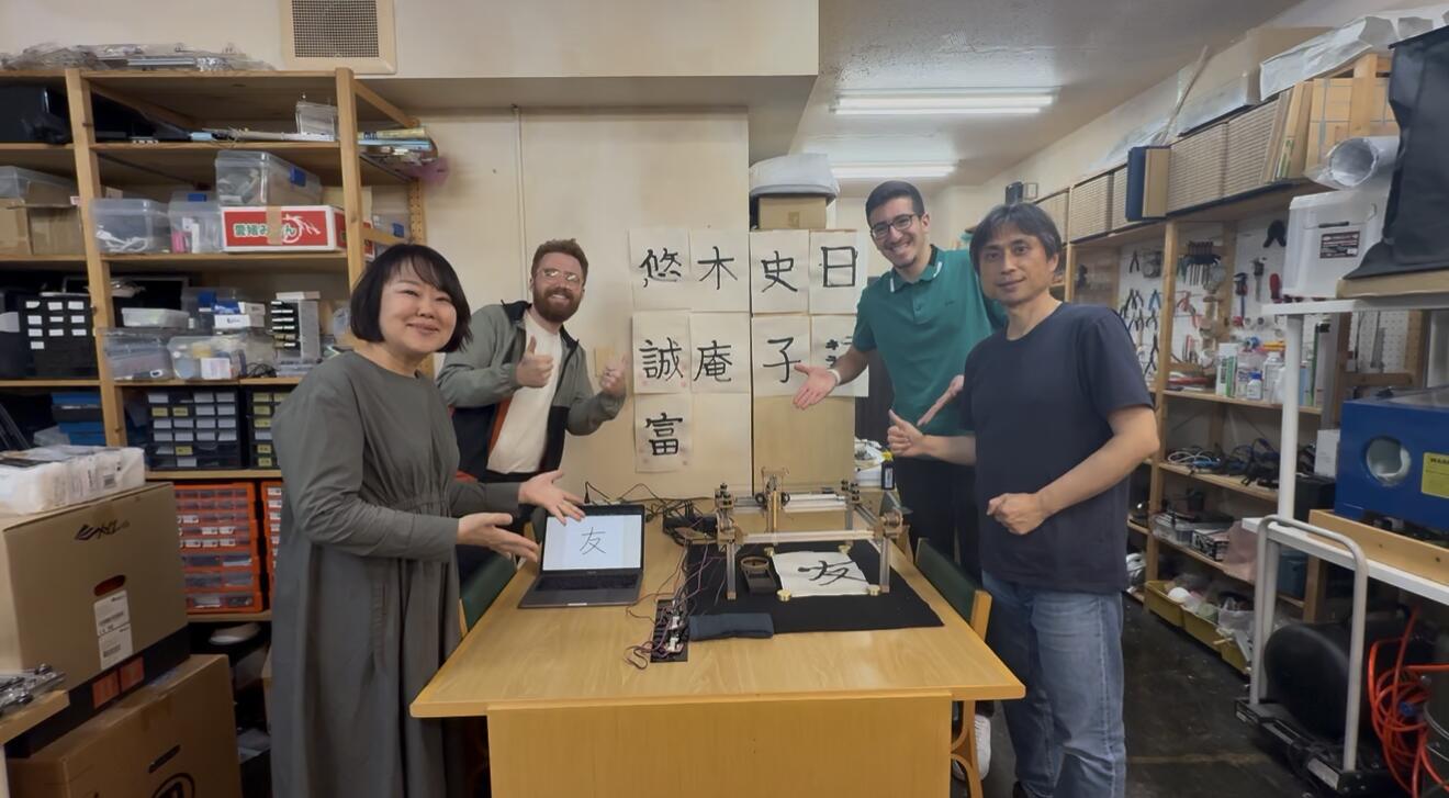
- Assembled the machine in collaboration with the rest of the team
- Created the final video
- Worked with Fumiko on the slide design
Jump to this week's checklist.
Group Assignment: Building a Machine!
Nothing much to add in this section other than a referral to our group assignment page. It was an extremely fun process, and later in this page I document my individual assignment.
Learnings from the Global Session
This week's global session was co-led by Nadya Peek, who directs the Machine Agency at the University of Washington, and Jogin Francis, an electrical engineer and Fab Academy global instructor based at Superfablab Kochi in Kerala, India, where he works as technical lead and has spent years running students through the full stack of digital fabrication machines.
During the session, Nadya was visiting Nervous System (n-e-r-v-o-u-s.com), the generative design studio founded by Jessica Rosenkrantz and Jesse Louis-Rosenberg.
The Fab Academy recitation earlier on machine building was led by Jani, who has spent years iterating on the simplest possible workflow for putting a working machine together in a week.
Why stock parts and supply chains matter?
The first thing Nadya hammered on is that you should not be machining your own screws, lol.
Machines are mostly stock parts held together by other stock parts, and the whole point of using standardized components is that someone else has already done the hard work of making them repeatable, cheap, and available.
Vendors like McMaster-Carr, Misumi, Stock Drive Products, and Amazon Industrial exist precisely so that you can spend your time on the parts that are actually unique to your machine.
The flip side is that supply chains are not always reliable. If your design depends on a specific bearing or a specific extrusion profile, you need to check that you can actually get it before you commit, otherwise you end up redesigning the machine around whatever showed up in the box.
Fasteners: button head, flathead, shoulder, heat-set
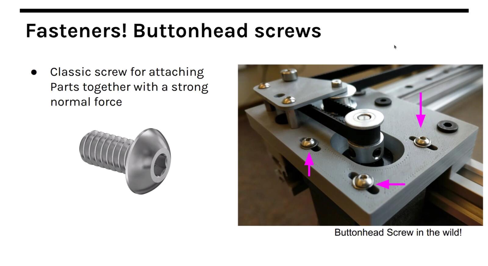
Fasteners are the most common stock part by a wide margin, and even within fasteners there are a lot of choices that matter. Button head screws have a rounded cap that sits proud of the surface and are the default for general assembly.
They give you a clean look and are easy to drive with a hex key.
Flathead screws (also called countersunk screws) sit flush with the surface because the head is conical and matches a countersunk hole. You use them anywhere you cannot have a screw head sticking up, like a sliding surface or a part that has to mate flat against another part.
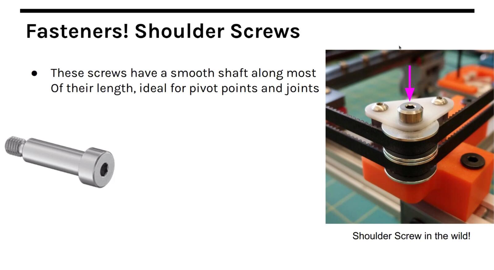
Shoulder screws are different in kind: they have a precision-ground unthreaded section (the shoulder) between the head and the threads, and that shoulder is what you use as a rotation axis. If you want a part to pivot freely on a screw, you do not use a regular bolt and hope, you use a shoulder screw because the diameter and length of the shoulder are toleranced.

Heat-set inserts are brass threaded inserts that you push into a plastic part using a soldering iron tip. The heat melts the surrounding plastic, the insert sinks in, and when it cools you have a metal thread embedded in the plastic.
This matters because plastic threads strip after a few cycles, but a heat-set insert lets you screw and unscrew the same fastener many times without destroying the part.
Joints and degrees of freedom
Once you start adding moving parts you need joints, and there is a small fixed vocabulary of joint types that covers almost everything you will build.
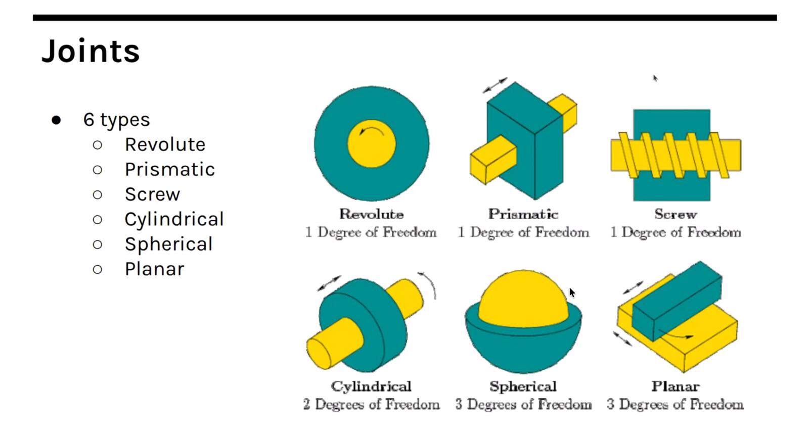
A revolute joint allows rotation around one axis (think of any Lego hinge or a door). A prismatic joint allows linear motion along one axis (think of a piston or a drawer slide). A cylindrical joint allows both rotation and translation along the same axis.
A ball-and-socket joint allows rotation around all three axes at one point (this is your shoulder or your hip, and it is much more common in biology than in engineering because it is hard to constrain and hard to actuate).
A universal joint (or Cardan joint) lets two shafts that meet at an angle keep transmitting rotation, which is how the drive shaft of a car copes with suspension travel. A planar joint constrains motion to a plane.
There is also a whole class of joints called flexures, single-piece structures that flex elastically instead of rotating or sliding on a contact surface.
The number of independent ways a part can move is its degrees of freedom, and the job of the joints in your machine is to remove the degrees of freedom you do not want and leave the ones you do.
A linear stage on a CNC has one degree of freedom by design, even though the carriage is a rigid 3D object, because the guide rails remove the other five.
Gears and drive trains
Gears are a whole field on their own. The standard tooth profile is the involute, which has the useful property that two meshing involute gears transmit rotation at a constant ratio regardless of small misalignment.
Cycloidal gears, helical gears (angled teeth, smoother and quieter), and herringbone gears (two helical sets back-to-back, which cancels the axial thrust) are all variations on this idea.
Planetary gearboxes pack a high reduction ratio into a small volume by orbiting smaller "planet" gears around a central "sun" gear inside a "ring" gear, and harmonic drives (also called strain wave gears) achieve very high reduction with almost no backlash by deforming a flexible cup against an outer ring.
Nadya pointed out that you can generate gear geometry programmatically with Grasshopper scripts, which I want to come back to because parametric gear generation is exactly the kind of thing I keep needing for small mechanisms in my final project.
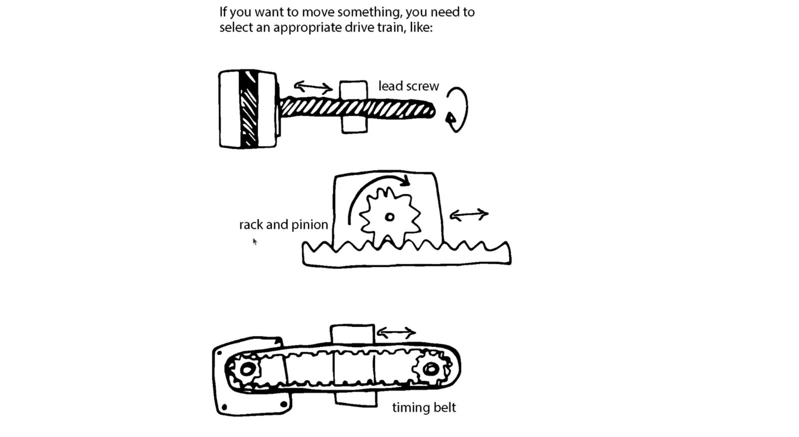
The drive train is the chain of components that gets power from the motor to the thing you actually want to move. Belts and pulleys, lead screws, ball screws, rack and pinion, capstans, and chains are all options, and which one is right depends on speed, force, precision, and budget.
Belts are cheap and fast but flex under load. Lead screws are slow and precise but inefficient. Ball screws are precise and efficient but expensive.
Serial vs parallel kinematics
Kinematics is the math of how the moving parts of a machine map onto the position of the tool.
The simplest kind is serial kinematics, where each axis is stacked on top of the previous one: the X carriage rides on the Y carriage which rides on the Z carriage, and to put the tool at a given XYZ point you just command each axis independently. Most hobby CNC machines and many 3D printers work this way.
The downside is that the upper axes have to carry all the lower axes, so the moving mass grows quickly and that limits how fast you can accelerate.
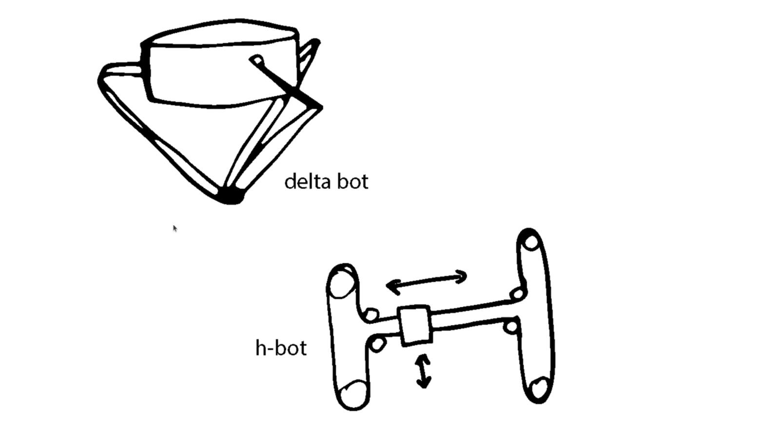
Parallel kinematics avoids that by mounting several actuators on the fixed frame and using linkages to share the load.
A delta robot has three motors fixed at the top of the frame, each driving one arm, and the three arms meet at a single end effector. A Stewart platform (hexapod) uses six linear actuators between two plates and can reach any pose in six degrees of freedom.
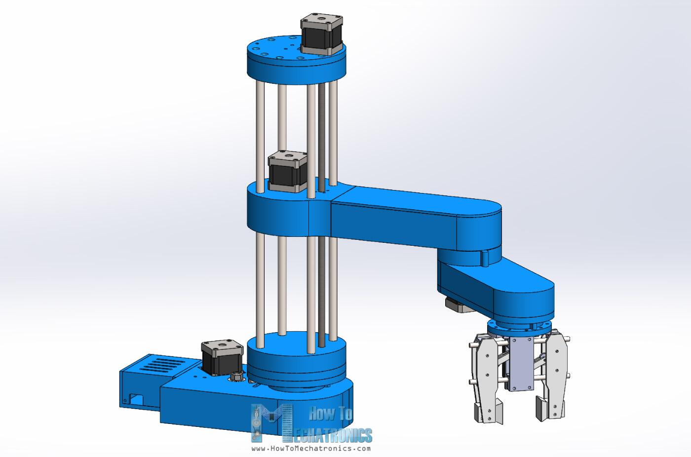
A SCARA arm, by contrast, is usually a serial robot with two rotary joints in the horizontal plane, so it belongs in the broader non-Cartesian machine discussion rather than as a parallel-kinematics example.
The tradeoff is that the inverse kinematics (going from desired tool position to required actuator lengths) gets harder to solve, but the moving mass is much lower so you can accelerate a lot faster.
CoreXY and H-bot are clever in-between schemes where two motors stay on the frame and a single belt routed in a specific pattern moves the tool head in X and Y. To move purely in X both motors turn the same way; to move purely in Y they turn opposite ways; arbitrary diagonals come from linear combinations.
CoreXY in particular has become the dominant architecture for fast 3D printers like the Voron, because the toolhead is light and the motors never have to move themselves.
Test by hand first
Nadya's rule: design the mechanics so you can move them by hand before you ever turn on the motors. If you can't push the carriage smoothly with your finger, no amount of clever control software will fix it. Friction, binding, and misalignment are mechanical problems, and the right place to find them is by hand, not by listening to a stepper motor skip steps.
Power budgets and what can go wrong
Every motor draws current, every controller dissipates heat, every belt has a tension that has to be reacted somewhere. These add up.
If you do not write down a power budget before you start, you will discover the shortfall the first time the machine stalls under load or the first time a 3 amp driver gets handed a 5 amp coil.
The same logic applies to the structural budget (loads, deflections, the stack-up of tolerances all the way from the frame to the tool tip) and to what mechanical engineers call an error budget.
Nadya showed two slides of "what could go wrong" that I want to keep close because they are basically a checklist. Mechanical problems compound, and catching them in design is a lot cheaper than finding them in assembly.
Any of the following could go wrong:
- Tool head
- Mechanical system
- Sensors and actuators
- Control system
- Applications and interfaces
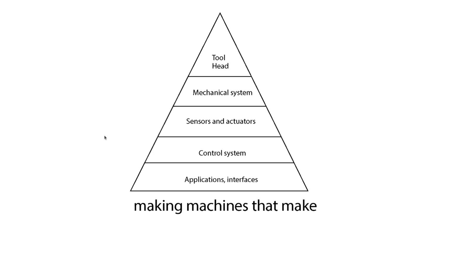
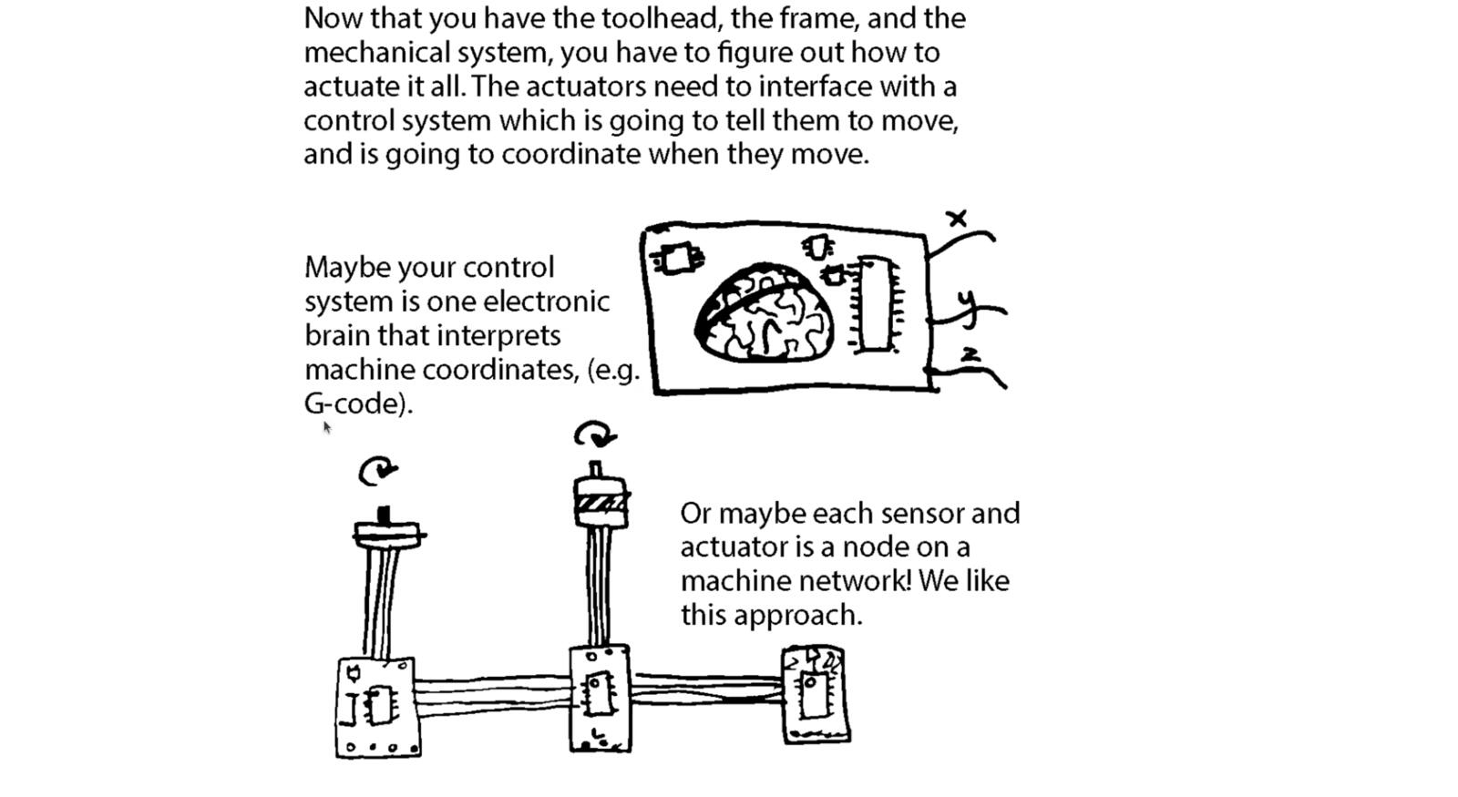
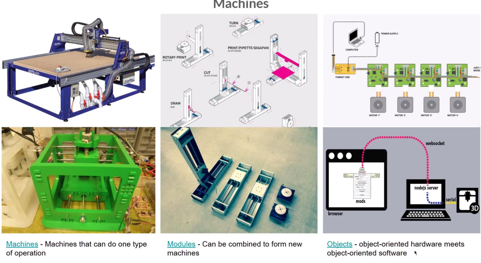
Here is what a machine generally consists of.
Object-oriented hardware
The idea of object-oriented hardware is that each physical subsystem (a motor + driver + sensor + connector) is treated like a software object: it has a defined interface, you can swap one for another, and the rest of the machine does not have to know how it works internally.
This is what makes modular machine platforms like Jubilee, Clank, MTM, and the Urumbu ecosystem work. You build a machine out of standardized modules that talk over a known protocol, and you can rearrange them without rewriting the firmware from scratch.
Open loop vs closed loop control
Open loop control means you tell the motor to move and you trust that it did. A stepper motor under normal load is open loop: each pulse is supposed to move the rotor by one step. The trade is that if you overload the motor, it skips steps silently and the controller has no way to know.
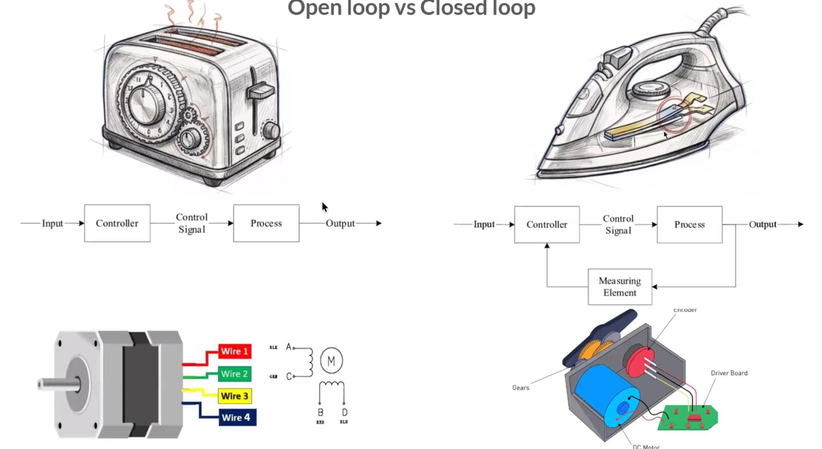
Closed loop control means you measure the actual output (position, velocity, force, temperature) and feed it back into the controller, which compares the measured value to the commanded value and corrects the difference.
The classic implementation is a servo motor with an encoder: you command a position, the encoder reports the actual position, the controller subtracts the two and drives the motor proportionally to that error.
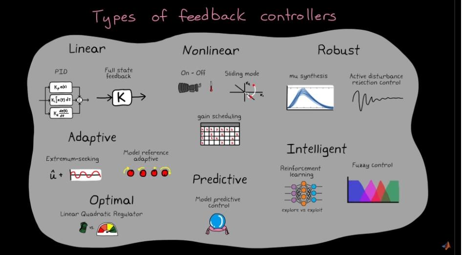
The simplest closed loop controller is bang-bang: if the error is positive turn the actuator on, if it is negative turn it off. A thermostat is a bang-bang controller. It works for slow, forgiving systems but tends to oscillate around the setpoint, the target value the controller is trying to maintain.
PID is the standard upgrade. The output is the sum of three terms computed from the error e(t): a proportional term Kp · e(t) which pushes harder when you are further off, an integral term Ki · ∫e(t)dt which kills steady-state offsets by accumulating past error, and a derivative term Kd · de(t)/dt which damps overshoot by reacting to how fast the error is changing.
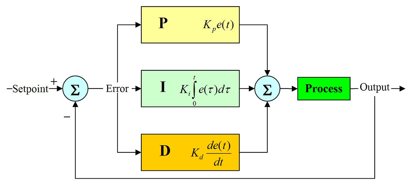
Tuning Kp, Ki, Kd is genuinely hard and there are entire books written on just that part.
For systems where PID is not enough, typically because the dynamics are too nonlinear, too fast, or too coupled, you reach for model predictive control (MPC). It solves an optimisation problem at every time step using a model of the plant to predict the next several seconds and pick the best control action. MPC is what runs on most modern process plants and on a lot of self-driving car stacks.
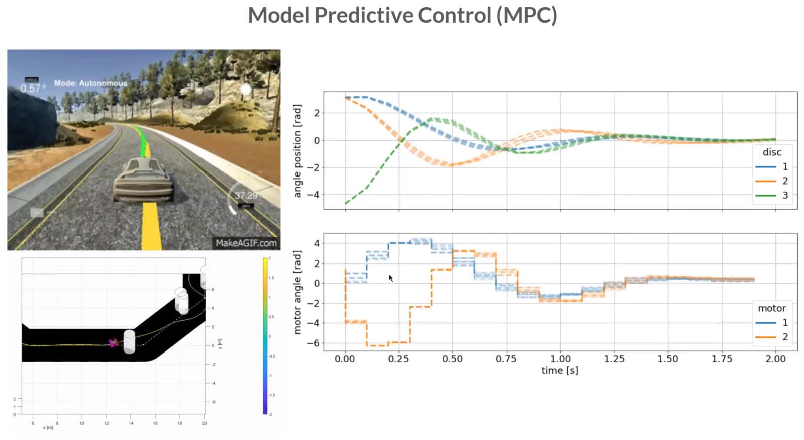
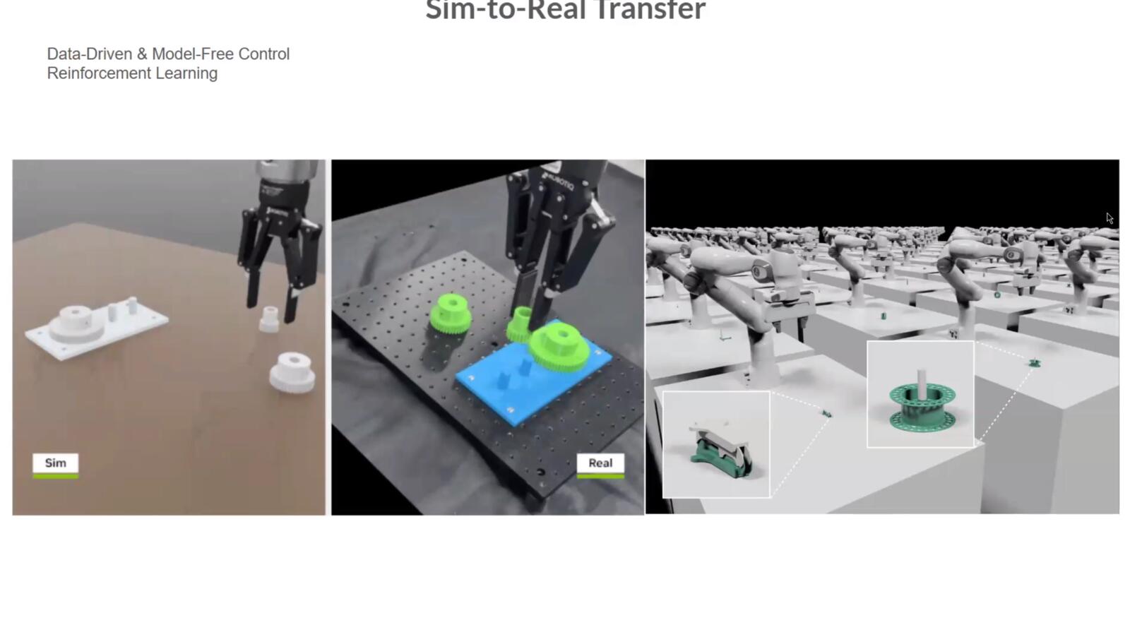
For highly nonlinear systems, you can train control policies in simulation with reinforcement learning and transfer them to the real machine. Modern legged robotics often mixes this with model-based control rather than relying on a single method.
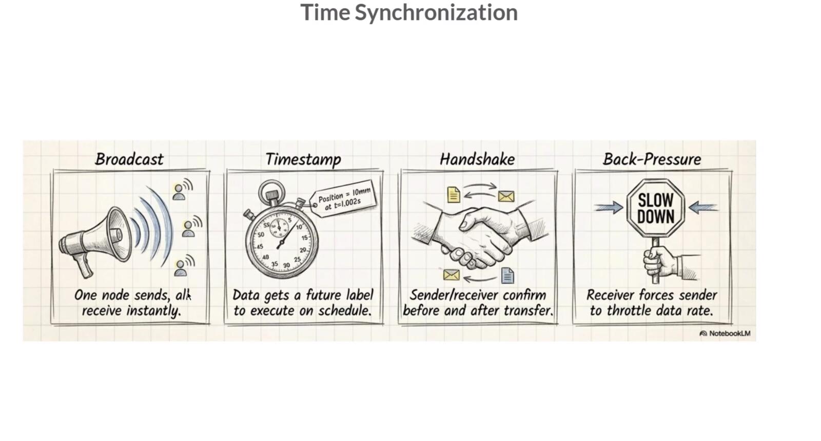
Coordinating multiple axes
To draw a diagonal line on a CNC you have to move X and Y in lockstep so that their ratio is constant over the whole move. To run a 5-axis mill you have to coordinate five actuators while keeping the tool tip on the commanded path.
There are a few different timing schemes for this: broadcast (one master sends a clock that everyone follows), time-stamped (each command carries the time at which it should be executed and the receiver buffers and waits), handshake (each step is acknowledged before the next is sent), and back-pressure (the slowest device throttles the others by refusing more commands until it catches up). Different machine architectures use different combinations.
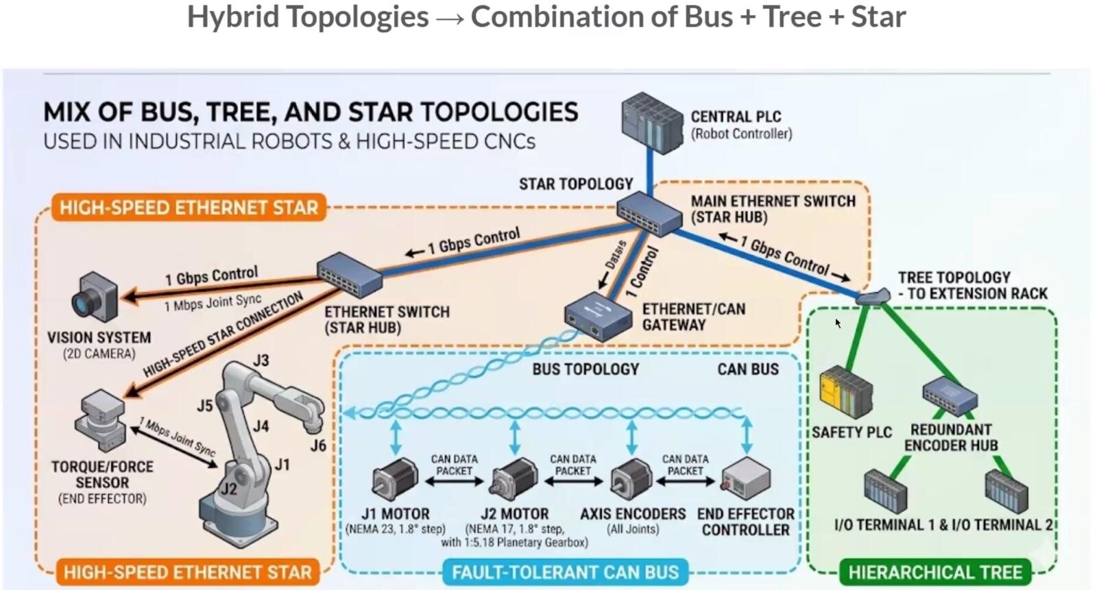
Communication protocols on a machine
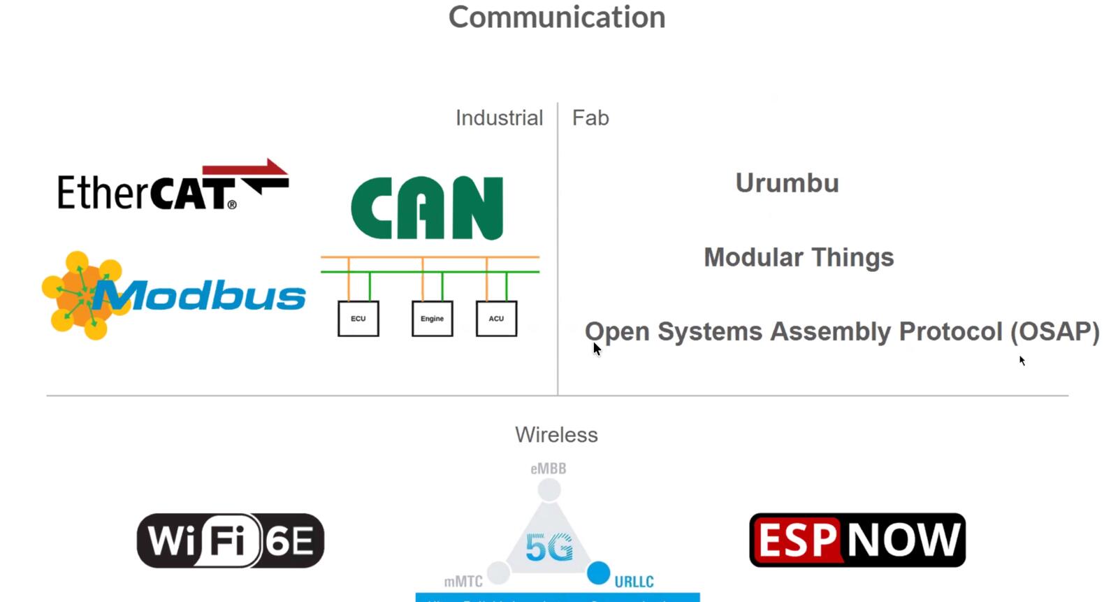
The actual wires connecting the modules use the same protocols I learned about in Week 11. UART for simple point-to-point serial. I2C when you have many low-speed sensors sharing two wires. SPI when you need higher throughput and you have spare GPIO pins for a chip select per device.
CAN is a differential pair with built-in arbitration that lets many nodes share one bus and resolve collisions automatically. CAN is what cars use, and it is increasingly what robots and machines use too because it is robust, prioritized, and tolerant of long cable runs.
EtherCAT is the high-end industrial option: it runs over standard Ethernet hardware but uses a special frame layout that achieves microsecond-level synchronization across many slaves on the same wire.
Path planning
Path planning is what turns a high-level command (cut this contour, draw this letter, move from here to there) into a sequence of low-level motor commands that respect the machine's velocity and acceleration limits.
There are static cases (5-axis machining of a known part on a known fixture, where you can plan everything offline) and dynamic cases (a waterjet cutting a sheet that is moving on a conveyor, or a robot avoiding obstacles in real time), and the algorithms are very different.
For static planning you usually generate G-code with a CAM tool. For dynamic planning you need an online planner that can replan as the world changes.
Software and motor controller landscape
The class page lists a lot of options that I want to keep around as a reference.
For motor controllers you have Pololu and Synthetos for hobbyist stepper drivers, ODrive for high-performance brushless servo control, RAMPS as the classic Arduino Mega shield for 3D printers, and Duet3D for more polished 3D printer control boards.
For host software you have Grbl and grblHAL as the firmware that runs on the controller, and Universal G-code Sender, Chilipeppr, Candle, and CNCjs as desktop or browser front ends that send G-code to the controller. Marlin is the dominant 3D printer firmware. FabMo is the academic/Fab-network alternative.
For modular machine architectures the names to know are Jubilee (a multi-tool open hardware platform from Nadya's lab), Clank (a low-cost CNC), MTM (machines that make machines), Urumbu (a modular I/O ecosystem with modules supporting I2C, 1-Wire, SPI, and other protocols), and the Open Lab Starter Kit. These are the platforms I will look at first when I start designing my final project's mechanical and motion subsystems.
My Contribution to the Group Work
Each person on our team contributed to a different aspect of this project. I talked about my work briefly in the group documentation, but here is a deeper dive.
Edited CAD Files + Assembled the Machine
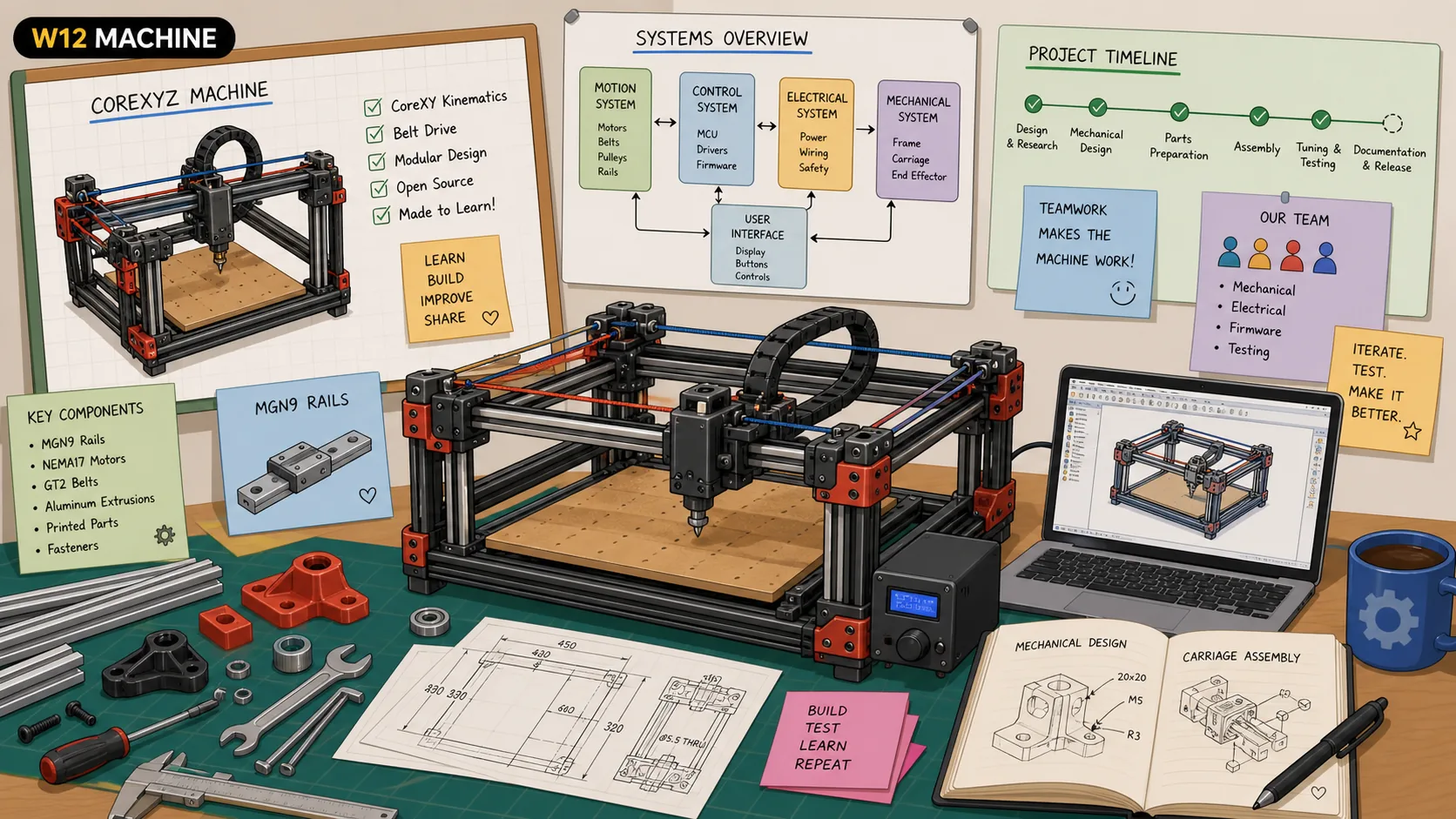
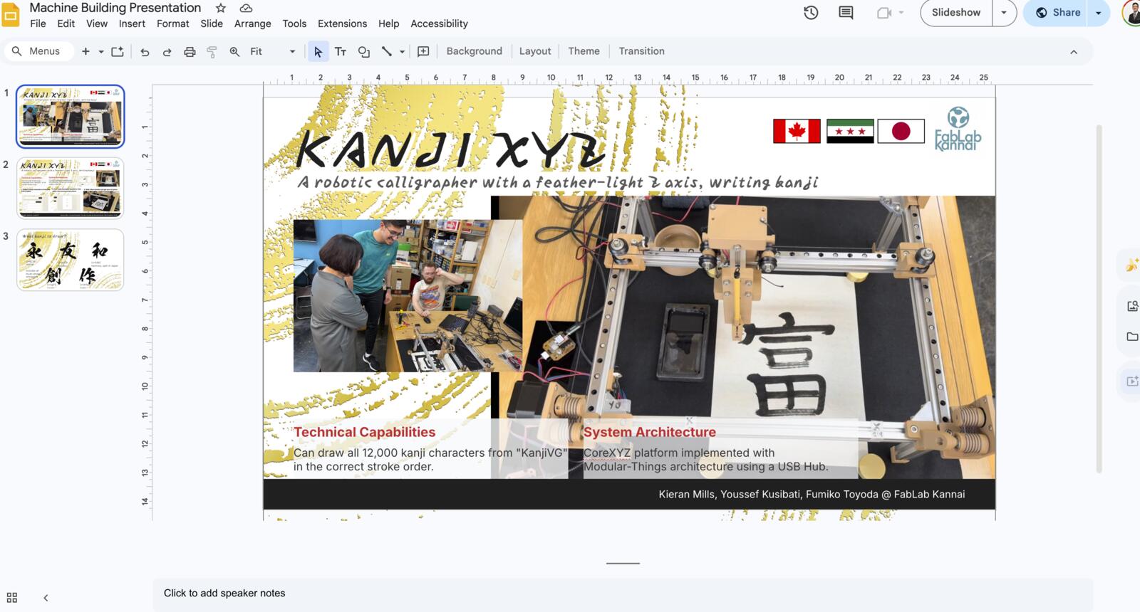
The CoreXYZ we built was based on Quentin Bolsée's mechanical work at the MIT Center for Bits and Atoms. Yuichi brought Quentin's CAD files back from the global instructors bootcamp, and those files became the starting point for our frame and moving parts.
Quentin gave the CAD/mechanical files, not the CoreXYZ control code. Yuichi created the control code with Gemini, using Quentin's mechanical platform as the base. Then, our team built the KanjiXYZ application code on top of that.
The designs we got needed some editing since Yuichi attempted to build a CoreXYZ machine but it had some issues. Here’s what I had to edit, all the design files are linked below:
- Add support to the motor holders
- Redesign the Z-axis bottom and top to make sure the thread goes up to it perpendicularity (90 degrees).
- Change the sizes of some nut holders
- Change the thickness of multiple pieces to fit with the screws
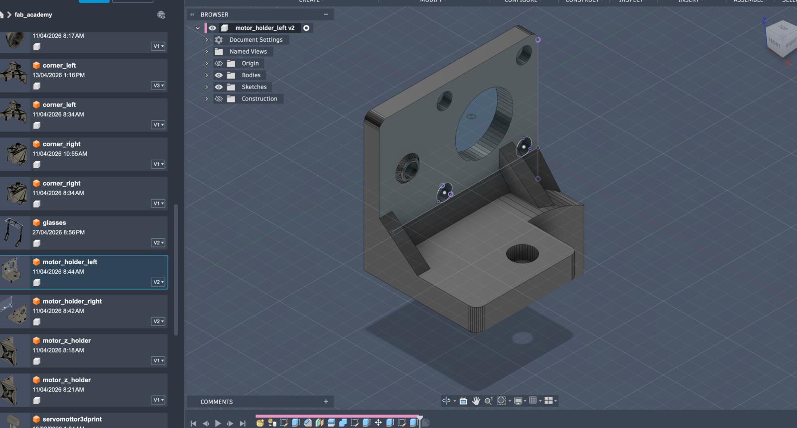
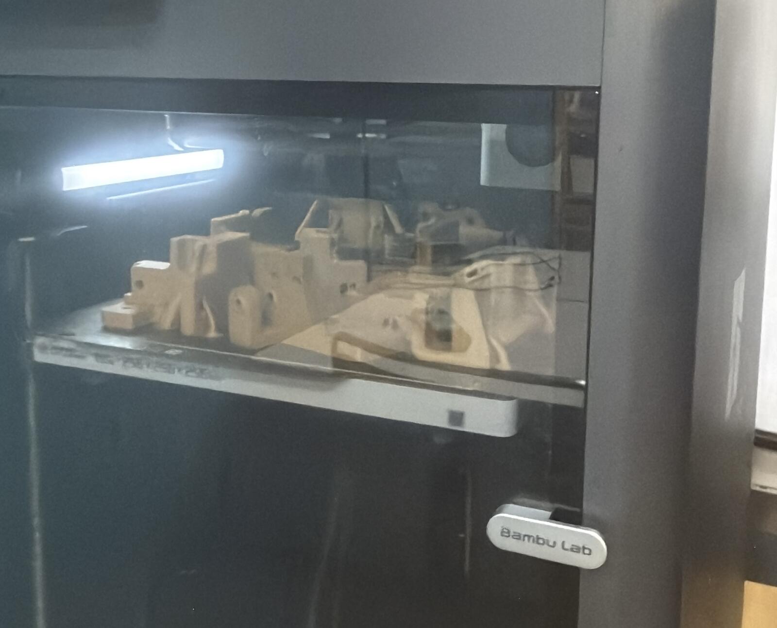
Additionally, after ordering all the parts needed for the machine, I worked with the team to assemble everything after 3D printing the additional parts. Here’s a timelapse of me working on the CAD design and Kieran assembling :D
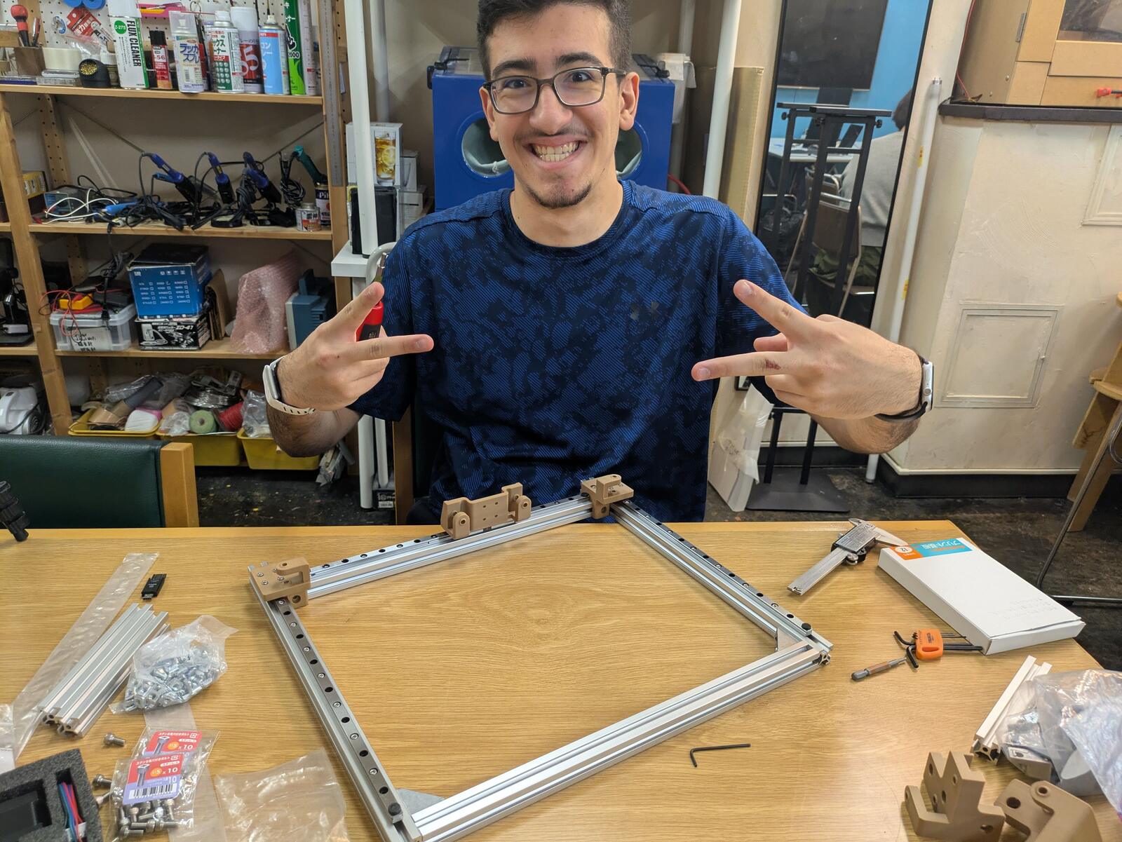
Created and Experimented with a New PLA Wood Filament
We wanted to give the machine a wood feel, so we ordered Creality Wood PLA filament from Amazon.
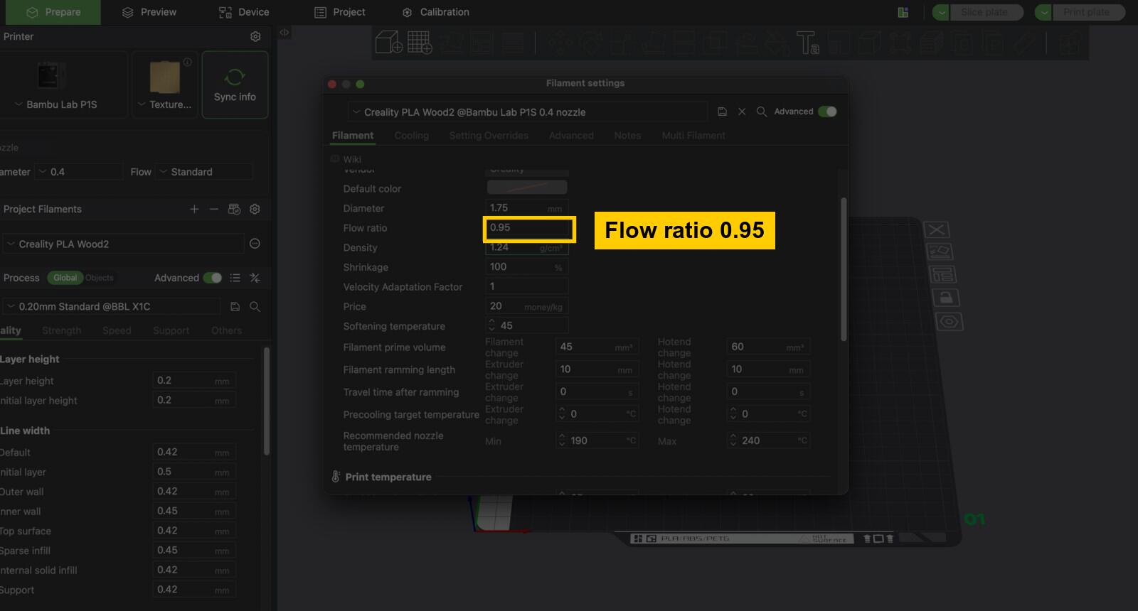
I went through a bunch of iterations starting from the Generic PLA preset, which took a lot of hours, lol. Here’s what worked, and you could find a downloadable preset in the original code and design section.
The first setting that helped was lowering the flow ratio to 0.95. I also increased the bed and nozzle temperature for the first layer in the slicer. The goal was to get the first layer to stick cleanly before worrying about speed.
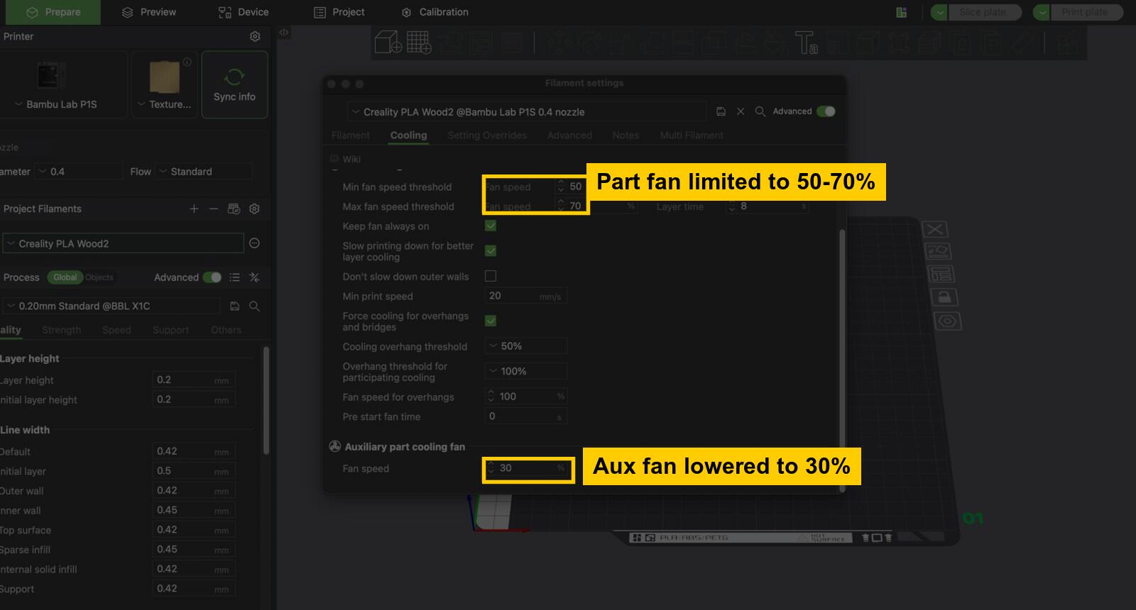
Next, I experimented with cooling. The setting that worked was keeping the part fan lower, between 50% and 70%, and lowering the auxiliary fan to 30%. That kept enough cooling for overhangs and bridges, but did not blast the wood PLA so hard that the layers separated.
After a bunch of attempts, the settings I mentioned work, and what was weird that I didn't find a preset online for it even though Creality filament is very popular.
Designed the Frontend and Integrated the Backend
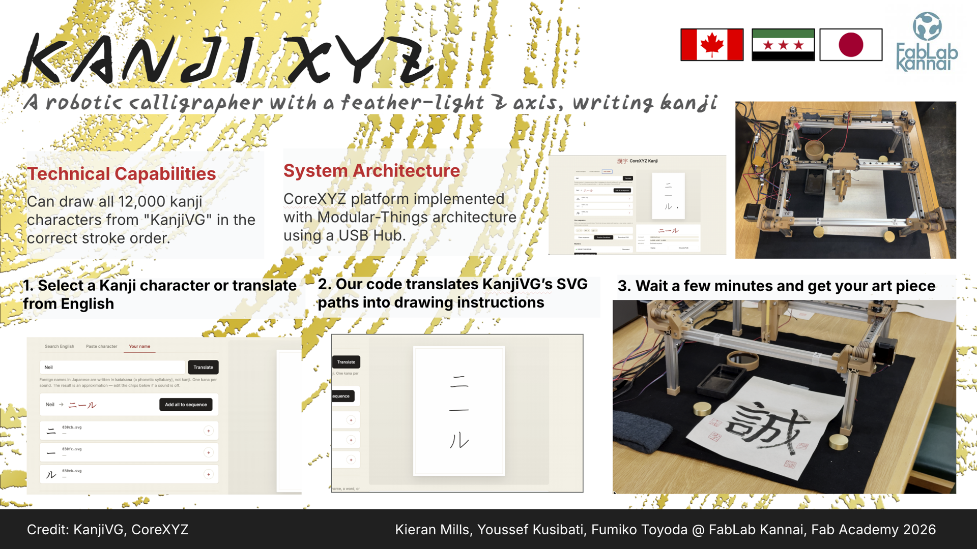
Kieran wrote the firmware and motor-control backend. My job was the layer on top of it: a Flask web server, a single-page browser UI, and the SVG-to-toolpath glue that turns whatever the user types into stroke data the backend can actually execute.
So this section is really three pieces fitting together: how the CoreXYZ mechanism works (because the backend's math is built around it), what the backend exposes as a Python API, and how the frontend talks to it over HTTP.
How the CoreXYZ mechanism actually works?
Our machine is a CoreXY in the X/Y plane plus an independent lead-screw Z. CoreXY is one of the parallel-kinematics schemes Nadya talked about in the global session: two motors stay fixed on the frame, and a single belt routed in a specific X-pattern moves the toolhead diagonally instead of stacking one axis on top of another.
The trick is that motors A and B do not correspond 1-to-1 to X and Y. They correspond to linear combinations of X and Y:
- Both motors turning the same direction → pure X motion
- Motors turning opposite directions → pure Y motion
- Any other combination → diagonals
The payoff is that the toolhead never has to carry the weight of a motor, so the moving mass is small and the machine can accelerate hard.
We added a third motor on a 4-start, 2 mm-pitch lead screw to drive Z. That one is a straight Cartesian axis and only handles pen lift, so it doesn't share belts with X/Y at all.
As I mentioned above, this is all based off of CoreXYZ developed by Quentin. Quentin's kinematics math is still visible inside kanji-to-motion.py: the comment # quentin's code for coreXYZ sits right above the goto_xyz() function we built on. Kieran then wrote the polished CoreXYZMachine class on top of that, and I wrote the Flask + browser layer on top of that.
The physical numbers baked into the kinematics:
capstan_dia    = 19.0   # mm, XY drive pulley
z_pitch        = 2.0    # mm, Z lead-screw pitch
z_starts       = 4      # Z lead screw is 4-start
steps_per_unit = 200    # full steps per motor revolution
# workspace: 180 x 180 mm in X/Y, 0-65 mm in Z
# pen up ~ Z=10 mm, pen down ~ Z=60 mm
And the inverse kinematics, the math that converts a target (x_mm, y_mm, z_mm) into three motor revolution targets:
xy_mm_to_rev = 1 / (capstan_dia * pi)
z_mm_to_rev  = 1 / (z_pitch * z_starts)
x_rev = x_mm  * xy_mm_to_rev
y_rev = -y_mm * xy_mm_to_rev
z_rev = -z_mm * z_mm_to_rev
motor_A_target = y_rev + x_rev   # CoreXY combination
motor_B_target = y_rev - x_rev   # CoreXY combination
motor_C_target = z_rev           # straight Z
That sum-and-difference is the whole reason CoreXY is called "core": the X-pattern belt routing is what physically implements that math. The backend does this math on every single move command before sending targets to the motors.
Here is an interactive CoreXYZ visualizer:
AI attribution
This interactive CoreXYZ demo was AI-generated and adapted to fit my site aesthetic based on Kieran Mills's Week 12 CoreXYZ demo.
The backend, briefly
The whole backend lives in three files under kanjixyz/backend/:
kanji-to-motion.py: Quentin's original CoreXYZ test harness. It includes a MockMotor class that drives a Python turtle window instead of a real motor, and the goto_xyz() function that holds the kinematics formula. We used this to dry-run kanji paths in a turtle simulation before sending anything to real hardware.
motor.py: driver for one motor controller. Each Motor opens its own USB serial port to one controller board and exposes set_position, set_target_position, set_current, get_states, etc.
kanjiXYZ.py: Kieran's main work, linked above: the CoreXYZMachine class that holds three Motor objects (A, B, C), runs the inverse kinematics from the section above on every move, and exposes the high-level operations the frontend actually calls: set_origin, move_absolute, move_rel, wait_for_move, disable_all, plus the SVG-aware extract_svg_paths, discretize_path, and draw_kanji_routine.
Crucially, the low-level backend is not limited to “kanji” as a concept. Once it has an SVG file, it extracts every <path d="..."> string, parses the path data with svg.path, samples each drawable path into a fixed number of points along the curve, and treats the resulting list of (x, y) points as the toolpath.
In the normal web UI, those SVGs come from KanjiVG character files, but the machine-side parser itself only cares about SVG path geometry. Pen up vs pen down is handled by moving Z between z_up and z_down between strokes.
The frontend (the part I built)
The frontend is a Flask app (app.py) plus a single-page browser UI (templates/index.html, static/app.js, static/style.css). Flask is a lightweight Python web framework.
When I run python app.py, Flask starts a local server on my computer. The browser can then request pages or data from that server, usually through a URL like / or /api/search.
Flask connects each URL route to a Python function. For example, the / route returns the main HTML page, while /api/search runs Python code that searches the kanji data and sends the result back as JSON.
On the browser side, static/app.js uses fetch() to make those requests:
fetch(`/api/search?q=${query}`)
That line asks the Flask server for search results. Flask receives the request, runs the matching Python route in app.py, and sends the data back to the browser. In this project, that is how the interface asks Python to search KanjiVG, combine SVGs, preview paths, or pass movement commands to the backend.
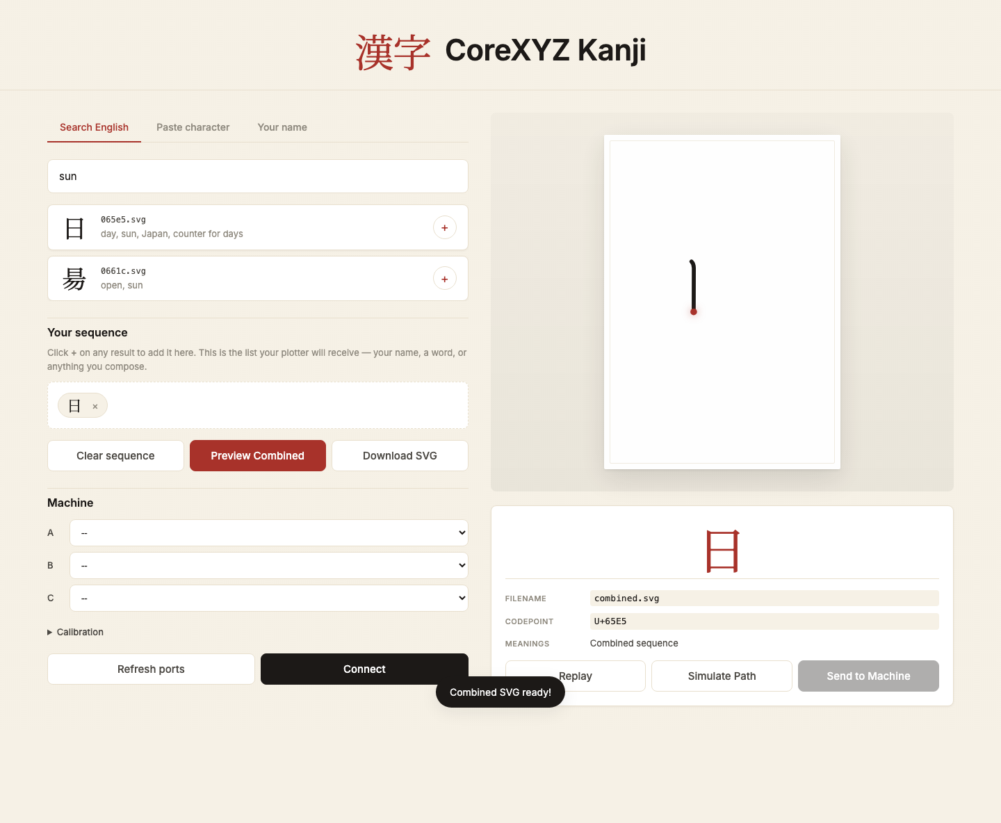
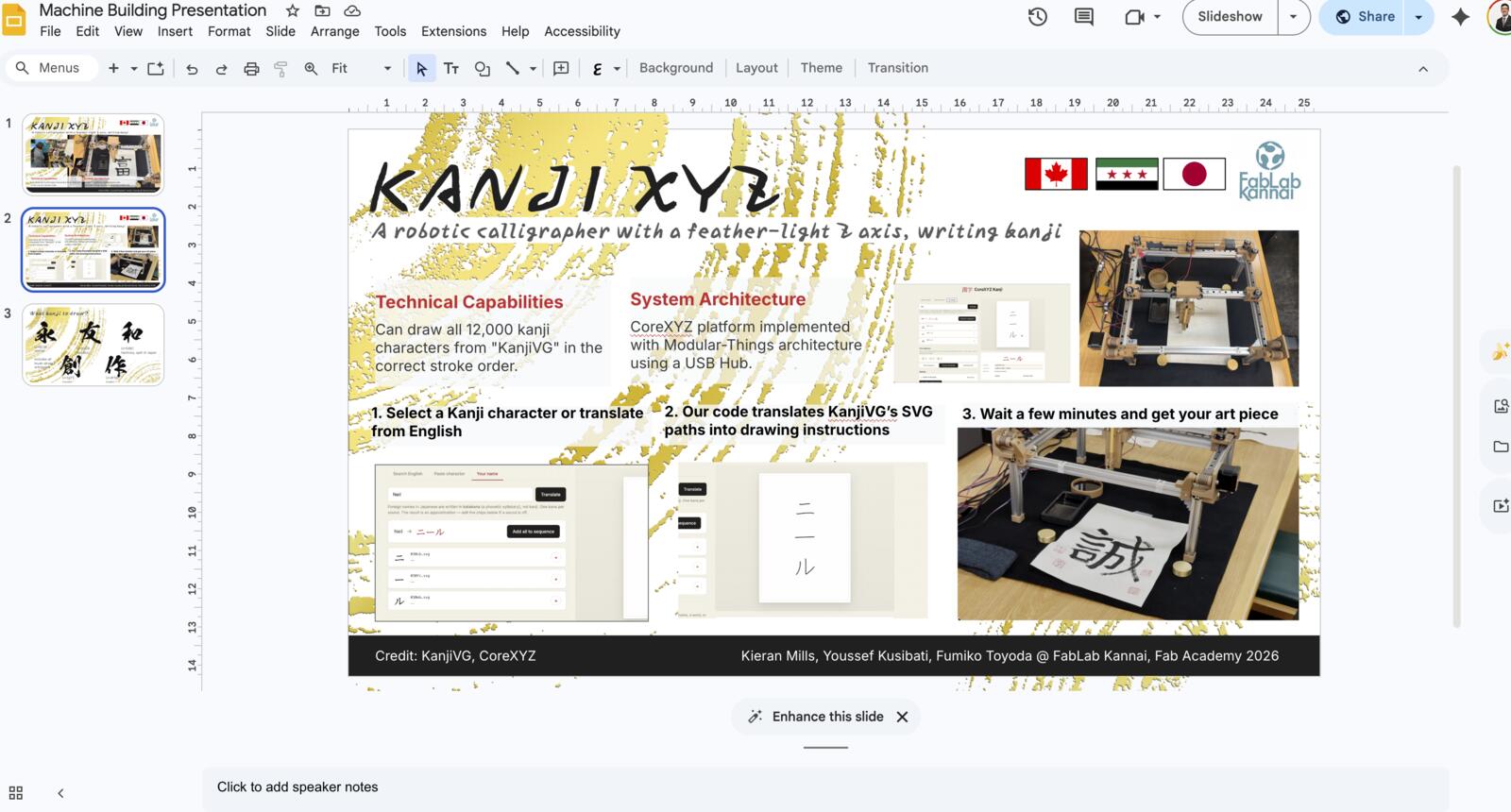
It lets the user pick characters three different ways:
- Search English → kanji: typing "sun", "love", "fish" hits a local index I build from KANJIDIC2 at startup, filtered to the kanji that actually exist in KanjiVG
- Paste character: paste any kanji or kana from the OS IME or clipboard, it gets resolved to a KanjiVG SVG
- Your name: English name → approximate katakana, using a longest-match transliteration table (3-letter patterns like
tch/schfirst, then digraphs likesh/ch, then CV pairs likeka/ki/ku, then orphan consonants)
Whichever path the user takes, characters land in a "sequence" chip strip. That's the staging area for the composition that will eventually go to the machine.
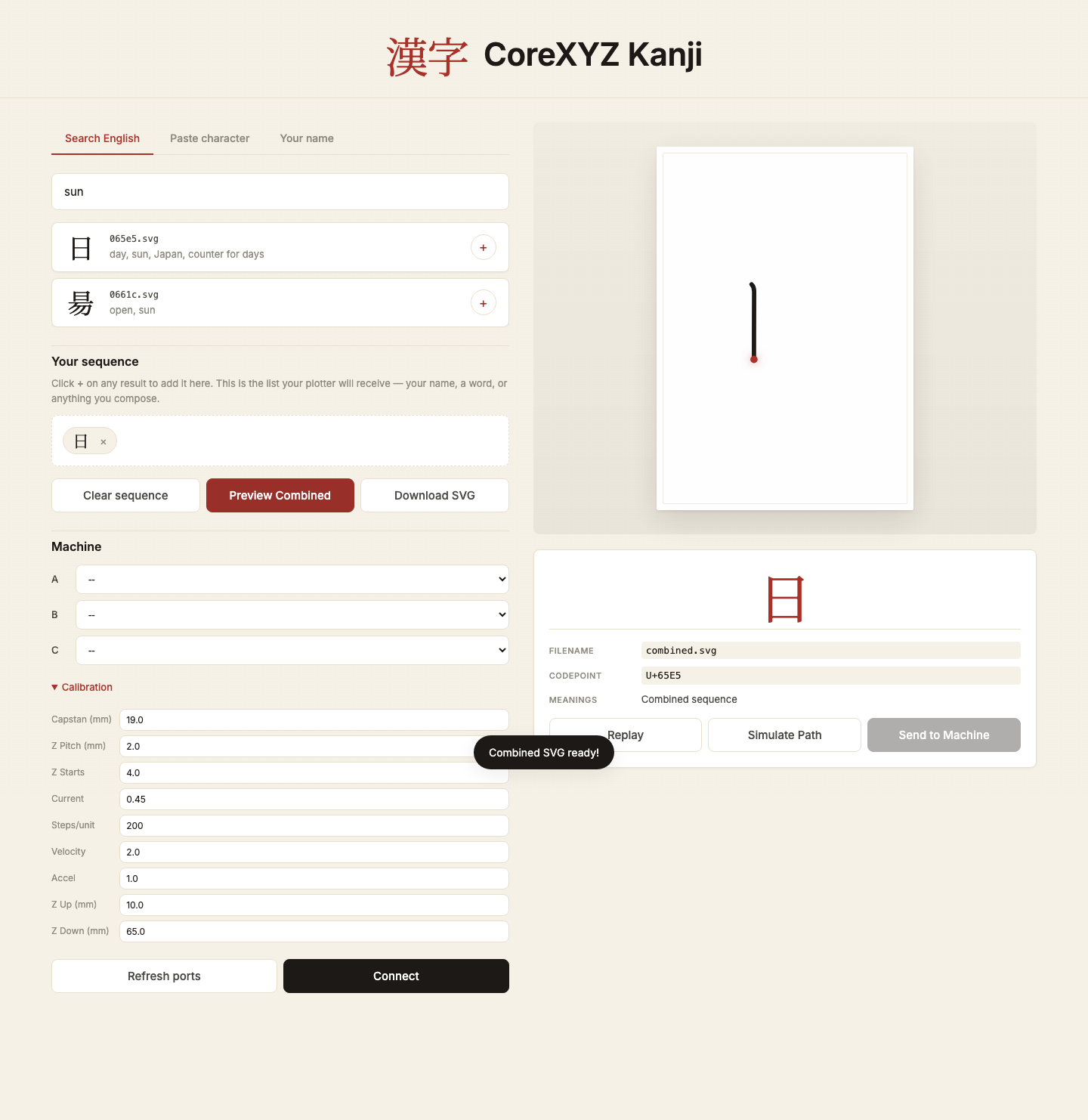
There's also a machine panel: serial-port pickers for motors A/B/C, a calibration drawer (capstan diameter, Z pitch, current factor, velocity, accel, Z up/down, every constant from the kinematics is editable), jog buttons, set-origin, plot, and a big red emergency stop.
Running the Flask code
The code bundle is here: Kanjixyz frontend and backend code.
After downloading and unzipping it, the Flask entry point is frontend/app.py. I have to run it from the frontend/ folder because app.py expects kanjidic2.xml, kanjivg_codes.txt, templates/, and static/ to be next to it.
The steps are:
- Download the zip file.
- Unzip it.
- Open Terminal inside the unzipped folder.
- Go into the
frontend/folder. - Install the Python requirements.
- Run
app.py.
cd frontend
python3 -m venv .venv
source .venv/bin/activate
pip install -r requirements.txt
python app.py
Once Flask starts, it prints a local address in the terminal. For this app, I open http://127.0.0.1:5001/ in the browser.
From there, the normal flow is:
- Search for a meaning, paste a character, or type a name.
- Add the character to the sequence.
- Click Preview Combined to generate one SVG.
- If the machine is connected, refresh the serial ports and select motor A/B/C.
- Set the origin and send the combined SVG to the machine.
The search box calls /api/search?q=sun. The backend looks up the English meaning in kanjidic2.xml, filters the result against the KanjiVG codepoint list, and sends the matching SVG filenames back to the browser.
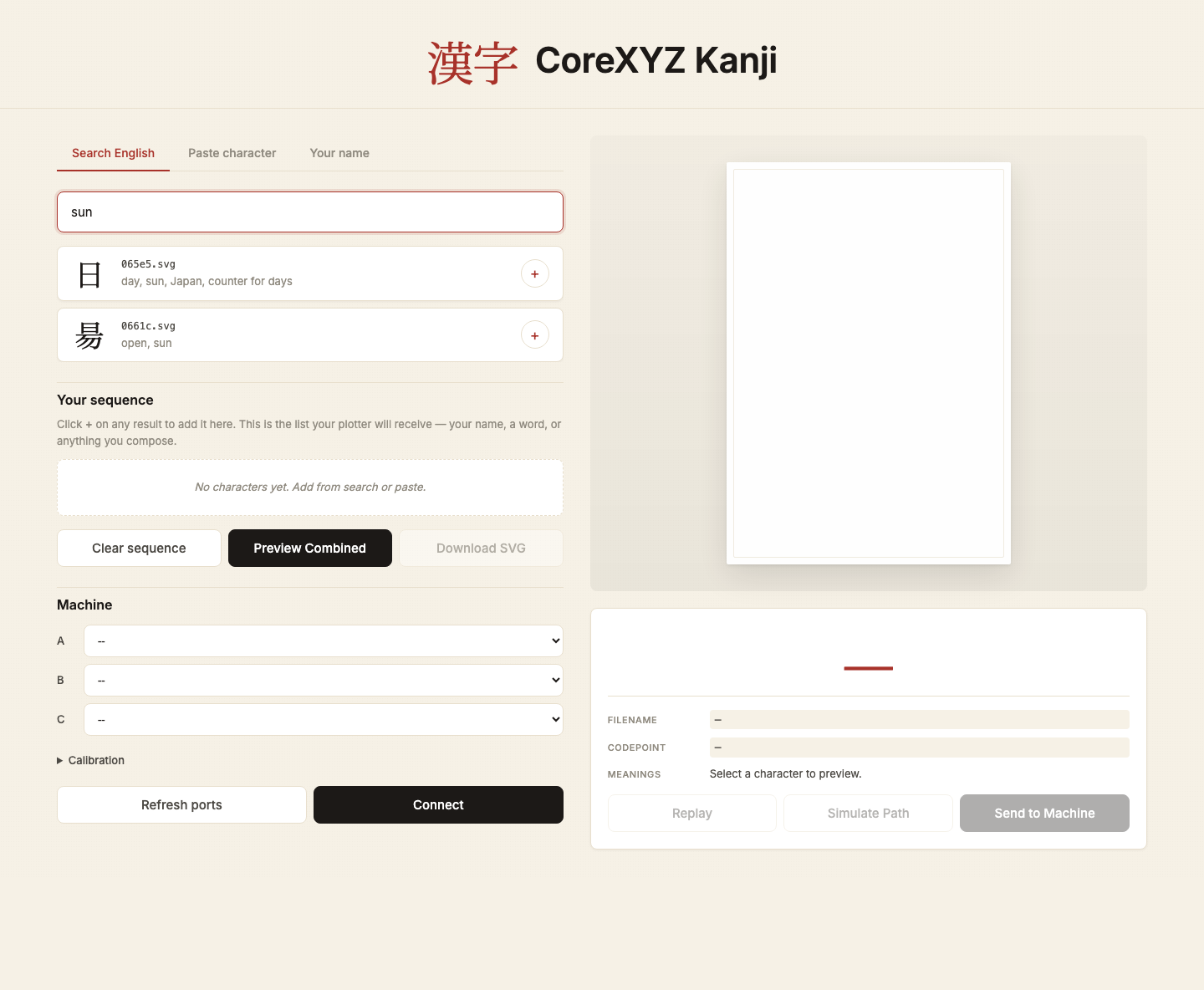
sun.When I add 日 to the sequence and click Preview Combined, the browser sends the selected filename to /api/combine-svg. Flask builds the combined SVG and returns it to the page, where the frontend renders and animates it.
The machine panel is where the web UI turns into the hardware controller. Without the machine connected, the search and preview parts still work. To actually plot, I need to refresh the serial ports, select motor A/B/C, check the calibration values, connect, set the origin, and then send the combined SVG to the backend.
Composing your own sequence and combining into one SVG
Once there are characters in the sequence, clicking Preview Combined (or Plot Sequence later) tells the backend to stitch them into one SVG. This is where the user is essentially authoring their own kanji composition: picking the characters, deciding the order, and getting a single drawable file out the other end. A name, a phrase, a custom mix of kanji and katakana, anything that's a list of KanjiVG codepoints.
The combining logic lives on the backend in compute_layout() and build_combined_svg(). The flow is:
-
Pick a layout. With
ncharacters in the sequence:- 1, 2, or 3 chars → vertical column (top to bottom, the way Japanese is traditionally read)
- 4 or more → square-ish grid:
cols = ceil(sqrt(n)),rows = ceil(n / cols), with any incomplete final row centered
Each cell is
CHAR_SIZE = 109units wide with aCHAR_GAP = 15unit gap between characters. -
Resolve each character to its KanjiVG SVG. The backend pulls each
<codepoint>.svgfrom the KanjiVG CDN (cdn.jsdelivr.net/gh/KanjiVG/kanjivg) and caches the text in memory after the first hit. Every kanji in KanjiVG is a sequence of<path d="...">strokes in the correct stroke order. - Translate the path data. For each character at layout position
(offset_x, offset_y), the backend walks every segment of every<path d>and adds the offset to the start, end, and control points. That's thetranslate_d_string()helper, with a case for each segment type the SVG path spec supports (Move,Line,CubicBezier,QuadraticBezier,Arc,Close) because each carries its coordinates in a slightly different shape. - Stitch into one document. The translated path strings are concatenated into a single
<svg viewBox="0 0 total_w total_h">with each<path>rendered withfill="none" stroke="#000" stroke-width="3". That's what the preview canvas displays, and it's exactly what the machine will draw if the user hits Plot.
There are three things the user can do with this combined SVG:
- Preview (
POST /api/combine-svg): returns the SVG text inline so the frontend can render it in the A4 panel and animate the strokes one by one withstroke-dasharray/stroke-dashoffset - Download (
POST /api/combine-svg/download): returns the SVG as a file, so the user can save their composition or open it in Inkscape - Plot (
POST /api/plot/combined): same combined SVG, but the backend immediately writes it to a temp file and startsdraw_svg()in a worker thread
Because the backend is what handles SVG path translation and concatenation, the frontend never touches the SVG path strings itself; it only sends the list of filenames.
The combine and the plot endpoints share the same build_combined_svg() function under the hood, so what the user previews on screen is exactly what the machine draws. No last-minute coordinate drift between the on-screen and on-paper versions.
How the two halves actually talk
The frontend never touches the motors directly. It talks to Flask, and Flask owns the single CoreXYZMachine instance. Every interaction is an HTTP call:
GET  /api/search?q=...        English → kanji lookup
GET  /api/convert?char=...    metadata for a single character
GET  /api/name?name=...       name → katakana → characters
GET  /api/ports               list available USB serial ports
POST /api/connect             open motor ports A/B/C, push calibration
POST /api/origin              zero current position as (0,0,0)
POST /api/jog                 step move on one axis
GET  /api/machine/status      live X/Y/Z, plotting flag, etc.
POST /api/combine-svg         return a stitched SVG for preview
POST /api/simulate            return the discretized toolpath
POST /api/plot                start a draw job (single character)
POST /api/plot/combined       start a draw job (whole sequence)
POST /api/plot/stop           halt the current job
POST /api/emergency           cut motor current immediately
State that has to survive a request (current X/Y/Z, whether origin is set, whether a plot is running, connection status) lives on the CoreXYZMachine object inside the Flask process. That means restarting the server forgets the connection — not the worst tradeoff, since the physical machine still needs to be re-homed anyway.
Step-by-step: what happens when you draw 日 (sun)
- User types
sunin the search box. The browser debounces 200 ms, then sendsGET /api/search?q=sun. - Backend looks up
sunin the in-memoryENGLISH_TO_KANJIdict (built from KANJIDIC2 at startup), filters out anything KanjiVG doesn't have, returns[{kanji: "日", filename: "065e5.svg", codepoint: "U+65E5", meanings: [...]}]. - User clicks + to add 日 to the sequence chip strip. The frontend stores it in a JS array and re-renders.
- User clicks "Preview Combined" →
POST /api/combine-svgwith the list of filenames. Backend downloads each SVG from the KanjiVG CDN (cached in memory after first hit), translates each path'sdstring by the per-character layout offset, and returns one combined SVG plus its bounds. - Frontend injects that SVG into the A4 paper preview and animates the strokes one by one using
stroke-dasharray/stroke-dashoffset. - User clicks "Refresh ports" →
GET /api/ports, which on Mac lists/dev/cu.usbmodem*. User picks A/B/C and clicks Connect →POST /api/connectwith the chosen ports plus the current calibration values from the drawer. - Backend opens three serial connections, sets steps-per-unit and current factor on each, and zeros the target — the
Motorconstructors handshake over COBS USB serial. - User jogs the head to the back-left top corner with the X+/X-/Y+/Y-/Z+/Z- buttons. Every click is
POST /api/jog→move_rel(dx, dy, dz, distance_mm)→execute_kinematicsruns the CoreXY math and pushes new targets to motors A, B, C. - User clicks "SET ORIGIN" →
POST /api/origin. Backend resetspos_x/y/zto 0 and tells each motorset_position(0)so the firmware also forgets its previous count. From here on, every move is clamped to0..180 mmin X/Y and0..65 mmin Z. - User clicks "Plot Sequence" →
POST /api/plot/combined. Backend writes the combined SVG to a temp file, thendraw_svg(svg_path)runs in a worker thread:- extract every
<path d>from the SVG - discretize each one into ~15 evenly-spaced points along the curve
- normalize the overall bounds and scale them into a 180×180 mm canvas with 10 mm padding
- for each stroke: lift Z to
z_up, travel a transit line to the start, drop Z toz_down, trace the points, lift Z again - between every move,
wait_for_move()pollsis_movingon all three motors at ~100 Hz until they settle
- extract every
- The frontend polls
GET /api/machine/statusduring the job to update the live X/Y/Z readout and the plot status indicator. - At any point, the EMERGENCY STOP button hits
POST /api/emergency, which setsemergency_stop = Trueand zeros motor current. Every loop in the backend (jog, plot, transit, draw routine) checks this flag between steps, so a single click reliably stops a moving machine without needing to kill the Flask process.
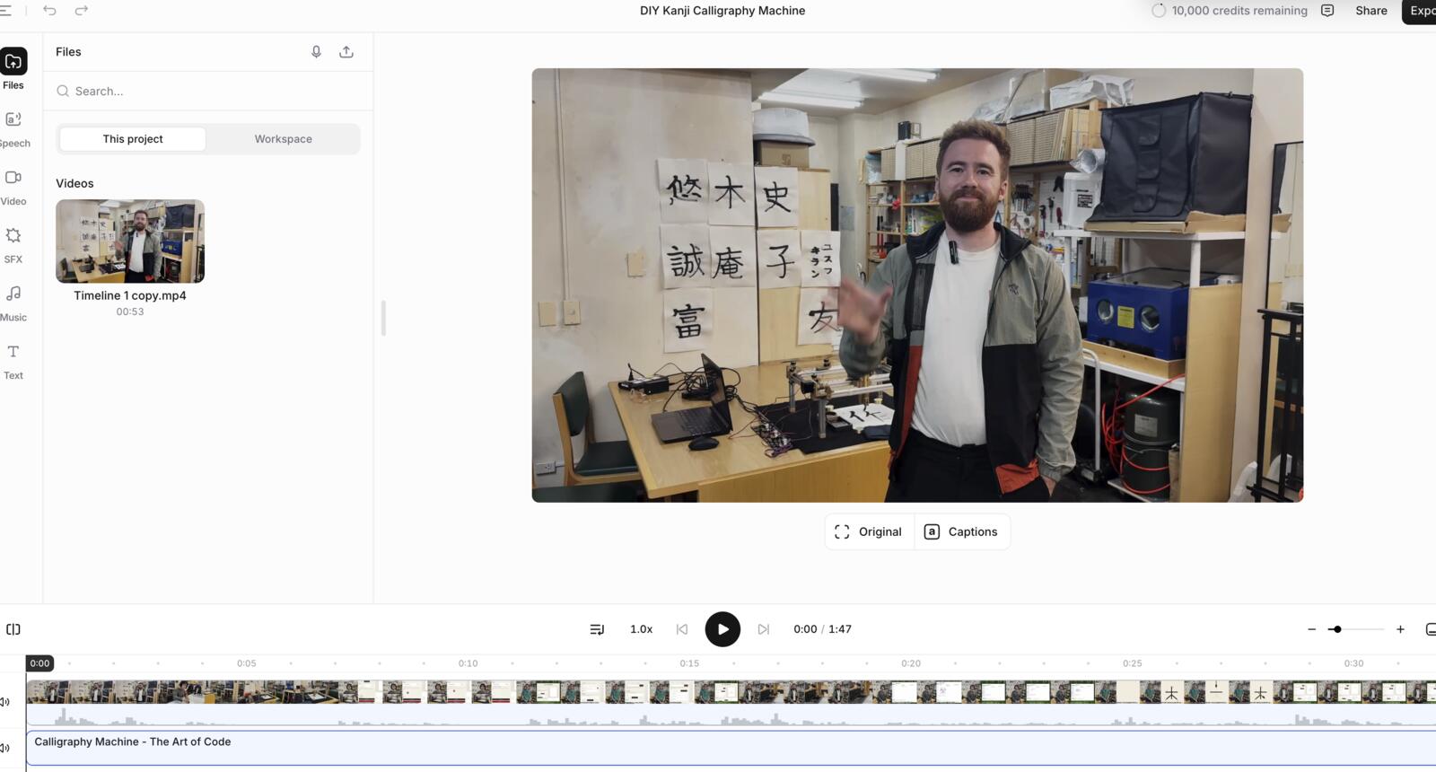
Created Final Video + Slide
I saw a bunch of videos from the years before, and to be honest, I didn’t like the heavy reliance on voiceovers. I wanted to make us appear in the video, so I told the team I will take point on the creating the video.
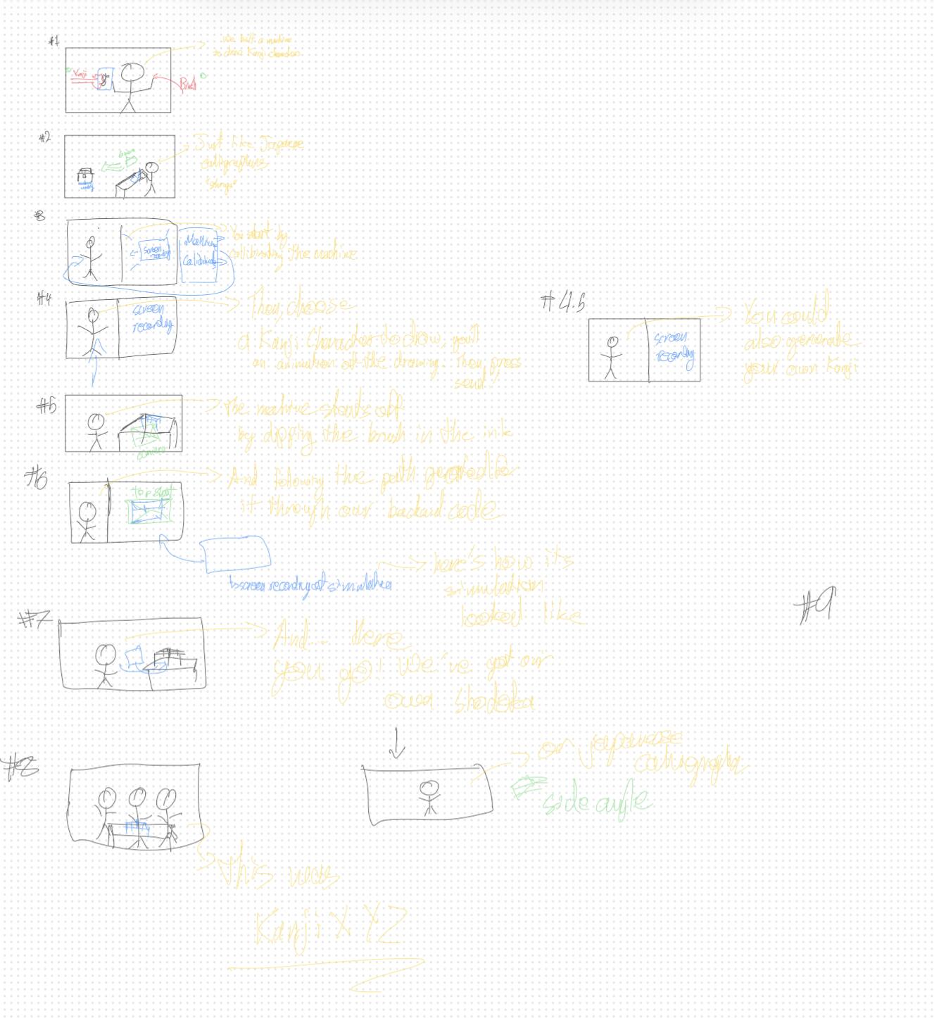
I started with storyboarding. Here’s how it looked like. We weren’t very strict about the script itself as we changed it as we filmed the video. Yes, it was stupid to write the script in yellow.
We filmed the video which was a ton of fun and had a bunch of bloopers xD. It was a ton of fun too.
Halfway through recording, my microphone stopped working and we didn’t realize that till we finished and we needed to redo that part. I was so embarrassed ngl.
Then, I used Davinci Resolve to edit and produce the video. It was my first time on Davinci, but I used Premiere Pro and After Effects extensively previously.
One fun fact about footage shot on iPhone is that when using the mov files directly, the colors become pale essentially and you need to color grade or import them differently.
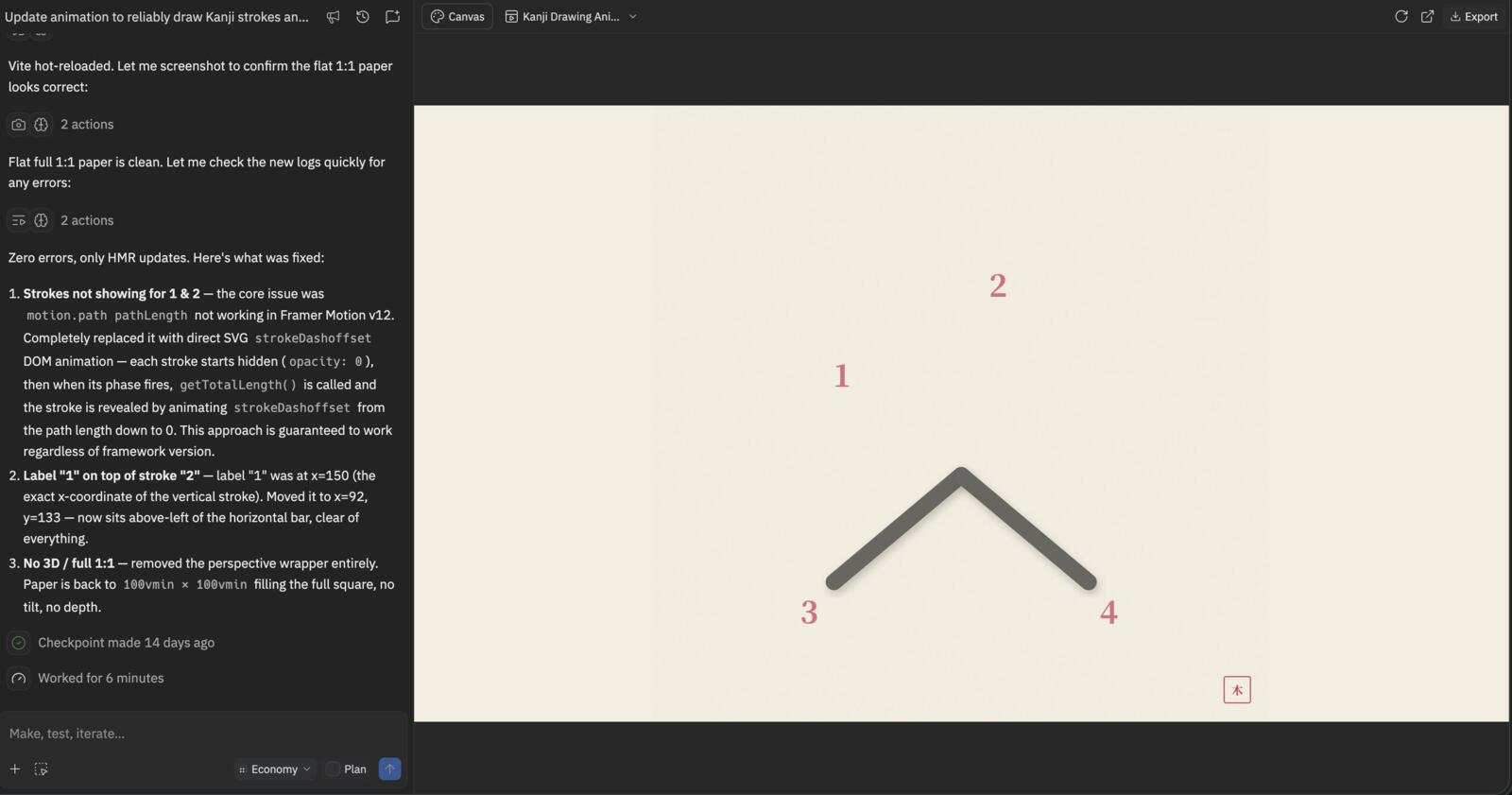
I created an animation in the video using Replit, which was pretty cool to demonstrate how far AI has come…
I didn’t find the type of music I wanted, so I tried generating it using ElevenLabs, which was pretty cool tbh.
Original Design and Code Files
This Week's Checklist
- Document Individual Contribution