INTRODUCTION
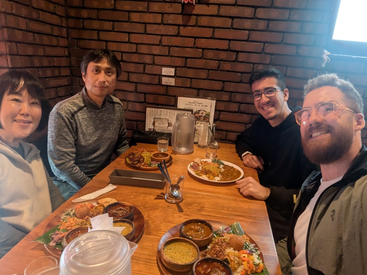
I've arrived in Japan and have made the switch from ESAN to Kannai in one piece! After nursing the 13 hour jet lag, I finally was able to meet my classmates, Youssef and Fumiko, as well as my incredibly gracious host and mentor, Yuichi. Thank you for having me in Yokohama! よろしくお願い!
[x] Design a machine that includes mechanism + actuation + automation + application
[x] Build the mechanical parts and operate it manually
[x] Actuate and automate your machine
[x] Document the group project
[x] Document your individual contribution
You can read our full planning and implementation of our week spent building this machine over on our group assignment page. On this personal page, I will be reflecting on my individual contributions to the assignment and what I've learned.
CoreXYZ
The CoreXYZ platform builds upon the principles used in the CoreXY platform. It is able to actuate an effector with three degrees of freedom using a series of pulley systems that can slide a series of gantries across linear rails. The implementation looks complex but the physics behind it is actually quite simple! It was very helpful for me to understand the motion by isolating each axis and even looking at how each of the three motors works. I've asked Gemini to create a simulation in the style of my previous works to aid with explaining it. You can control each motor individually or run the kinematics equations below to achieve movement in a single axis.

➔ Demonstration
AI Prompt Attribution
Working with this machine was a great way to dip my toes into learning more about kinematics. I never took a lot of physics in university, and tend to shy away from projects that involve a lot of complex movement, but this platform was simple enough to understand, especially if you start reading about CoreXY first. Because the two kevlar threads loop around that top gantry from opposite sides to keep the frame perfectly symmetrical and prevent binding, any movement from Motor C inherently drags the effector along the X-axis by pulling tension on one side while providing slack to the other.
Planning
Our first day was all about defining the scope of our machine and our action items for the coming days to make sure we could finish by our goal of Friday. Again, you can read about this process on the group assignment page to hear more about what we decided on and what was completed. I took the initiative to start jotting down ideas of what was being said in the room on my iPad, and had it broadcast to the main TV in the lab.
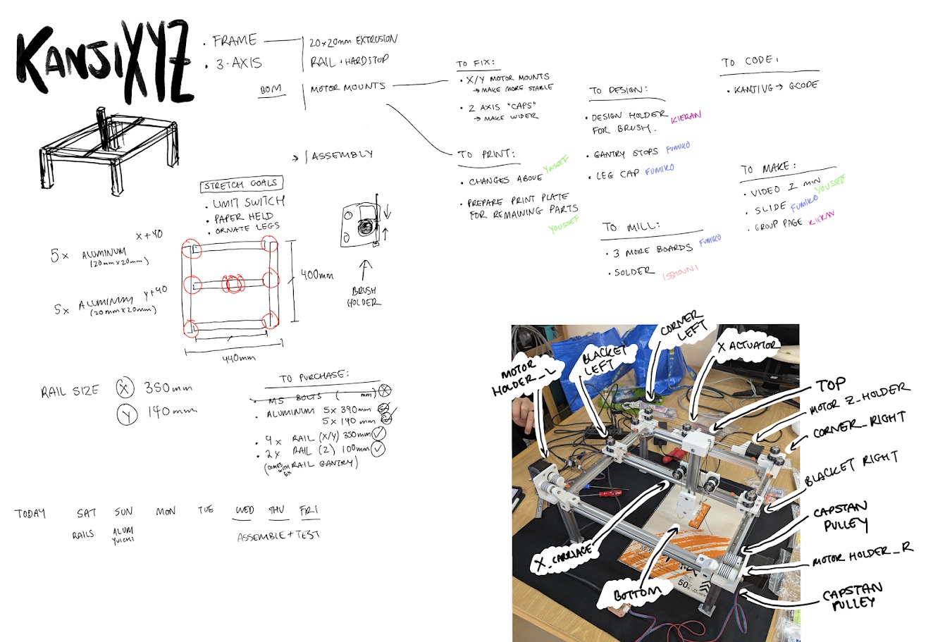
This helped us formulate a plan of attack for the week and get started with all of our excitement!
➔ 3D Model Modifications
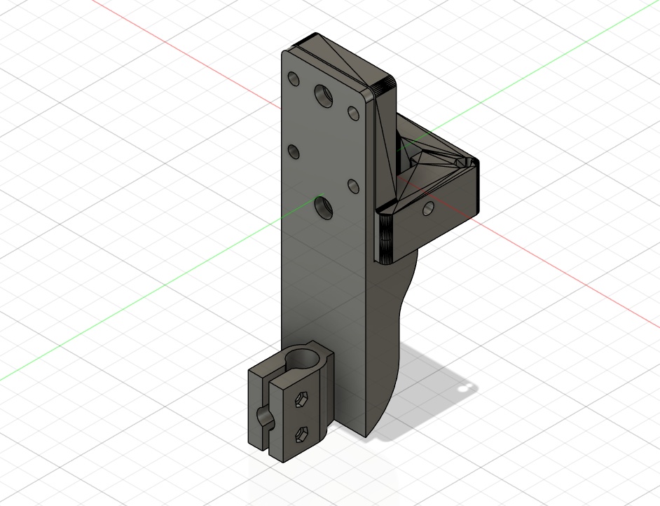
To allow us to properly adapt the original CoreXYZ model to work with our idea, we had to make a few modifications to the 3D models provided to us from Quentin via Yuichi. For this, I designed a brush holder in Fusion which you can download here.
KanjiVG
I contributed my time the first few days writing a python script that converts the vector path data in SVGs into X,Y coordinates for our machine. I stumbled across a really cool open-source project called KanjiVG, which has SVG files for over 10,000 characters.
The best part about KanjiVG is that it doesn't just give you a flat outline of the text. It actually stores the exact stroke paths and traditional stroke order, which is exactly what a CNC brush needs to make the calligraphy look authentic and since SVGs are basically just XML files under the hood, I realized I could open them up and extract the raw geometric data to feed into our machine. You can read about how I did this on the group assignment page.
Before our real hardware was ready, I used turtle, a graphics drawing library in python, to create a GUI preview of the strokes to see if I was coding it correctly!
Ultimately it was a great opportunity to strengthen my python skills and incorporate libraries that others have made! You can check out the full script here:

Assembly
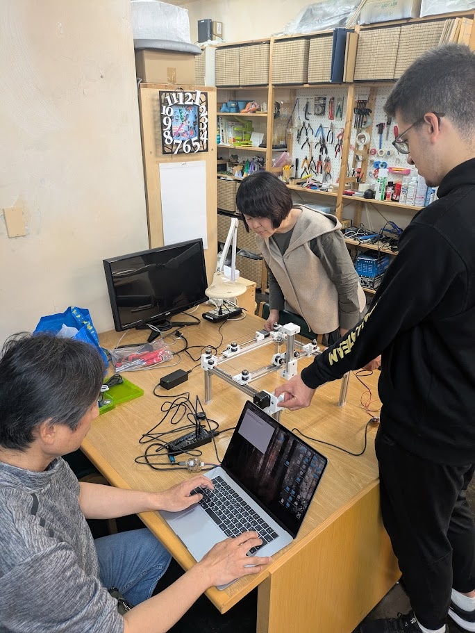
I spent the better half of a day putting the whole thing together with the help of my classmates. I wrote a whole section about what I learned on the group assignment page, including things you should look out for if you're building this with only Quentin Bolsee's documentation (took me a reaaaallly long time to figure out what he meant by "distal").
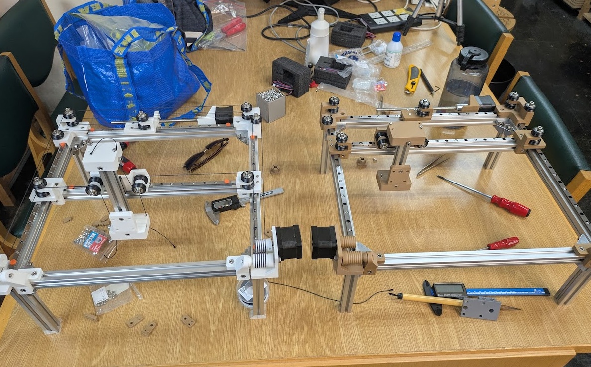
Here's our version (wood printed PLA) next to Yuichi's prototype.
Conclusion
I spent the better chunk of two days navigating the frustrating space trying to get this machine to work, and after a week of tinkering, I'm still not confident I fully understand it's quirks. That's the nature of physical things though. Our machine has a LOT of moving parts, a lot of sub-systems that are meant to mesh together perfectly, and if they don't you get some unintended behaviour in places that are very difficult to pinpoint. This whole assignment was a lot of fun - the highlight for me was getting to finally work with my classmates Fumiko and Youssef! Getting to working with something moving certainly pushed me out of my fabrication comfort zone, but I can confidently say after this that I'm not really into motors, haha. I think I prefer the kind of fabrication that doesn't move on it's own. Sorry to my robotics team if you're reading this. I'll be sticking to my little gameboy projects personally.