INTRODUCTION
As a high school teacher who teaches a lot of Arduino and breadboards, I feel like I have a pretty strong grasp on the concept of "Input Devices" as a whole. I often use the "IPO" model to teach how computers work to my students, in order to break down the concepts, pull back the curtains, and reveal how incredibly complex (yet still quite simple) our every day devices are.
Basically, an input device is something that allows a user (human) to interface with a machine (computer). The problem of course is that machines do not speak human or are able to "perceive" the world around us in the same way we do. Computers don't have eardrums, they don't have taste buds, or olfactory cells, or nerves and neurons. Machines can only listen to our natural world, really, through electricity. The problem then becomes trying to translate all the ways something can be "sensed" into an electrical signal. We have some pretty neat ways of doing this!
[x] Probe an input device(s)'s analog levels and digital signals (As a minimum, you should demonstrate the use of a multimeter and an oscilloscope.)
[ ] Document your work on the group work page and reflect on your individual page what you learned
[x] Measure something: add a sensor to a microcontroller board that you have designed and read it.

[x] For my students: Create simulations/demonstrations of common electronics interfacing
You can also read about our group assignment at Fab Lab Kannai here. I contributed some work on the oscilloscope, technically something I did in Week 10, but I've added it to Kannai's group site retroactively as my group members in ESAN were not available in my final weeks in Lima.
How Computers "Sense"
The important thing to note is that computers never really "know" what's happening in the real world, even with these sensors and actuators, it's still just an electrical signal. The computer is blind to the context that we (as humans) may see and hear and perceive. Our 5 senses, to a computer, can be interpreted by:
- Touch. Touch is detected solely through the completion of electrical circuits. You can have the resolution and force of that touch be more specific and precise, but at the end of the day, it's just electrons flowing. The same can be said for other force-based quanta, like sound and pressure. Temperature can be detected by warming a heat sensitive material that becomes less resistive as heat increases.
- Sight. Light is detected through changes in photoelectric chemistry of particular semiconductors (like Cadmium Sulfide) that free up electronics on contact with photos and allow current to flow with less resistance.
- Hearing. Sound is a physical wave that can move objects if they are small enough. Have that small object move in such a way that electrons can flow or stop flowing, and you've got something that can "hear" those waves.
- Smell. The presence of certain gases can restrict or allow the flow of electrons through certain conductors (like Tin Dioxide) and thus can be used to measure changes in certain compounds in the air.
- Taste. Okay, well this one, on a chemical level, is technically the same as smell but we haven't really found a reason for a home computer to need to taste anything (yet), so I'm leaving this one out of my explanation.
The wild thing is that, even if your computer can "sense" all of that data with different input devices, it's still only "responding" to it algorithmically. It's just boils down to 0s and 1s and logic gates. The 5 senses make a bad analog here because, not only do we have more than 5 senses, but the ways we interpret them still kind of boil down to neurons firing in some way.
Which begs an interesting question... How different are we from computers? Our biology could be described much in the same way that computers detect these stimuli. Our nervous systems communicate via electrical signals. The cells of our taste buds have binary receptors that only "fire" when a specific chemical is detected, which cascades to neurons downstream, eventually making it's way to the brain where we detect and decode what that neuron firing should mean. What we understand as "experiencing" something can be very deterministically stripped down to something that looks quite similar to binary. So who is to say that how experience the world is any different from how computers do? If anything, we're living in a time where a strong enough computer rivals the "computational" ability of a human brain (or even orders of magnitudes of human brains). What are we qualifying as sentient with that in mind?
Anyways. Enough philosophy. Let's talk about how each of these kinds of components work. You'll notice on my page this week a number of simulations. I was recently inspired by the recent addition of visualizations in Gemini for certain concepts. I was able to piece together a version of these visualizers by creating SVGs in Illustrator, exporting them to HTML with some tweaks to make sure it fit nicely with my CSS, then I asked Gemini to help me create the JavaScript logic for each. Here's the prompt I used to start each script.

You are an expert front-end developer and web animation specialist. Help me write vanilla JavaSript (not React) to animate several core concepts in electrical engineering for a widget on my website. I will provide you with a prompt that describes the concept as I want to convey it, how the user interacts with it, state machines to consider, the SVG objects and their names, the HTML layout of the site that I've already configured, and some CSS properties of the interactive components. [Insert individual prompt here]
➔ Buttons
A pushbutton, in reality, is just an open circuit that can be closed with your finger (or something else pushing it). These kinds of buttons can come in many flavours and sizes, and can either operate in a pulled-up state or pulled-down state.
AI Prompt Attribution
➔ Capacitive
We could also extend this understanding to capacitive devices, in a way. Your smartphone screen measures changes in an electrostatic field generated by your device. When your watery conductive flesh (finger) gets near this grid, it steals a tiny bit of the the electrical charge and this drop in voltage can be read at a specific X/Y coordinate and register as a "press" or touch.
AI Prompt Attribution
➔ Resistive
Potentiometers, temperature sensors, photoresistors (and probably more than I don't know) can be described as analog input devices, that is to say they read values that aren't binary, a range of values. They are read by your computer (or in our case, the microcontroller) as a change in voltage, as a result of this change in resistance. According to Ohm's Law, increasing resistance in a circuit will reduces the potential difference of the circuit if the current is maintained. This is generally achieved by placing a "voltage dividing" resistor in series with the variable resistor that the microcontroller can read in between. Rather than having it trying to interpret a random voltage value, it compares it against what it knows to be, for example 3.3V with a 1K Ohm voltage dividing resistor, and is able to see which "direction" the current prefers to move (path of least resistance).
The "ranges" from these devices may come from different stimuli:
- the turning of a nob that has a circuit with increasing resistance along an inner track
- the change of temperature along a material that loosens or stiffens when warmed or cooled, effectively increasing or decreasing the resistance
- the addition of photos to a light-absorbent material (such as Cadmium Sulfide) that loosens as the energy from the photons is transferred to the material
AI Prompt Attribution
➔ Magnetic
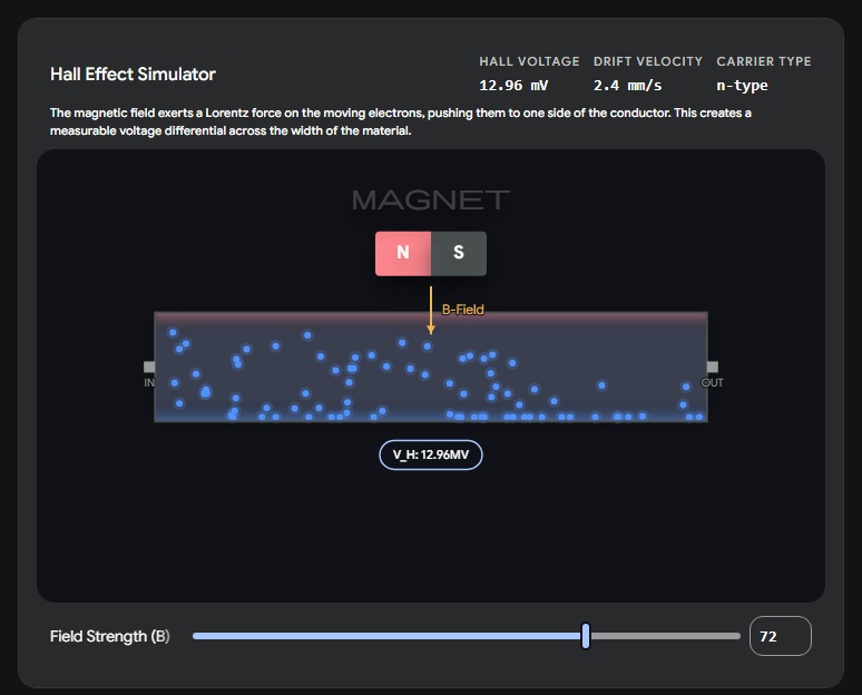
This group of sensors are admittedly the one's I have the weakest understanding of... and even with Neil's excellent drawings and explanations this week, I didn't take a lot of physics in university and still need to spend more time brushing up on my understanding of Lorentz Forces.
From what I understand, Hall Effect sensors like the ones we have in the lab, operate by detecting very minor differences in charge within the width of a wire (insane) caused by magnetic forces external to the wire (this is called Hall Voltage). These forces can come from all sorts of things. You could attach magnets on the cardinal directions of a joystick, and as you push the joystick in each direction, you can measure the change in that Hall Voltage in an adjacent wire.
AI Prompt Attribution
➔ Piezoelectric
Another tough one to wrap one's head around, but apparently some solid materials like crystals (and bone?!) accumulate an electrical charge when they are put under pressure (i.e. squeezed), and that electrical charge can be measured by literally wiring up the crystal to the circuit (and a resistor in parallel so the crystal can "reset" to it's baseline charge).
This is applied in practice with input devices like microphones, which have their crystals squeezed by the sound waves in the air (yeah, like it doesn't even need to be a LOT of squeezing) and output a change in voltage.
- I ran out of time trying to create a piezoelectric demo, but it's on my to-do list!
This also works in the reverse direction with output devices, you can make the crystal vibrate/oscillate when you apply an electrical charge to it, but hey - that's next week!
Data Lines
➔ GPIO
General Purpose Input/Output. This is essentially just a binary line. GPIO pins are configured to read 3.3V (or 1) or 0V (or 0). In reality, voltage fluctuates a bit for many reasons, so 3.3V is really anything in between ~2.2 and 3.3V, and 0V is anything in between 0 and ~1V. Anything in the middle is an unpredictable grey zone so most devices either ignore them or behave erratically when supplied with this amount.
AI Prompt Attribution
➔ GPIO + ADC
There is a special trick you can do with GPIO, and that's send analog data disguised as binary data down these lines. All you need is an ADC (analog-to-digital converter) either on your input device or baked into your microcontroller's pins. Let's say you've got a signal from an input device (e.g. a potentiometer) providing you with a non-binary signal (e.g. 1.5V). Depending on the ADC, that 1.5V signal is translated into a binary number (e.g. ADCs commonly use a 12-bit number, which could give us anything from 0 to 4096 - but in my example below I'm using a 4-bit number for simplicity) and then literally pulsed down the GPIO line one bit at a time. (e.g. so 1.5V would look like: 011101000101 and then this number is parsed on the microcontroller's end back to it's decimal equivalent)
AI Prompt Attribution
➔ I2C
Inter-Integrated Circuit. (It's a square, not a two. But I still call it "eye-two-see"). Uses two wires to intelligently send actual data, not just single 1s and 0s (okay, it's still sending single 1s and 0s, but they are part of a larger message containing many sections, including a start and stop command, and an address of who the message is intended for). It's able to do this by sending the data bits over the SDA (Serial Data) line and having them synchronize with pulses of 1s on the SCK (Serial Clock) line, so messages are only "read" when the SCK line is brought low.
"Low?", you're thinking... The extra little piece here is that devices that use I2C to communicate don't output voltage themselves, they only pull the data line and clock lines to ground (0V) when they want to speak. As a result, your I2C bus (the SDA and SCK lines) need to be pulled-high with resistors.
As a result, I2C devices generally need their own on-board interface circuits that can respond to messages from smarter devices, and to send packaged messages of their own.
The added benefit of I2C is that multiple devices can share this line! Because each message has an intended recipient baked into the packaged message, only devices who have their name called interact with the data being sent/received. Many devices can work at the same time here because data is generally spurted out in very quick pulses of usually no more than 32 bytes. I2C is a lot like how WiFi works in this way, you've got tonnes of data streaming over the air but your device only listens to the packets that have your MAC address attached to it.
AI Prompt Attribution
➔ SPI
Serial Peripheral Interface. This works in a similar way to I2C, but instead of addressing individual components in binary, we directly wire them up with something called a "Chip Select" pin. Each device has it's own CS. If that pin is pulled low (low for the same reason as I2C), then the other 3 pins in this interface (MOSI, MISO, and SCK) are essentially only used for the communication between these two devices. All other devices on these lines do not listen until their own CS line is pulled low as well.
SPI is a lot faster, not only because you have twice the number of data lines, but you can just dump a lot of data down these lines with a CS enabled. The trade-off here is that you need a dedicated CS line for each device you want to speak to.
AI Prompt Attribution
SHIFT REGISTERS
If you've been following my final project for Fab Academy, I'm trying to learn how to create handheld electronic devices. Ones that typically have buttons (many of them) to control a user interface, or an application, or a game. The problem we're faced with when it comes to that many buttons is that we only have so many "pins" on a device to communicate wether or not a circuit is open or closed. For just a 8 button device (4 directional inputs and 4 face buttons), you need 8 separate connections, plus lines to Vcc and GND. For baremetal processors, which I'm interested in working with for my final project, that's less of a problem, but for the XIAO development boards that I'm using to learn and prototype, 8 pins would immediately eat up almost all of the data lines I have.
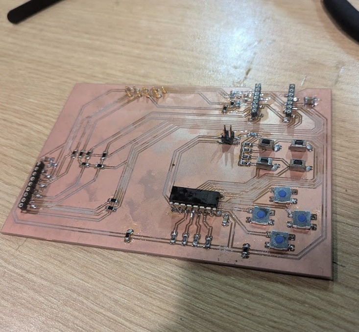
The solution: A Shift Register. You can think of this little chip like a USB hub for I/O pins on a microcontroller. Instead of having the XIAO listen to each of the 8 pins independently, instead we ask our shift register to listen to them, and then compile the states of each button as a byte that can be pulsed down a data line on series of clock pulses.
Anyways. What you're about to see below is one of the big circuits I spent basically all week trying to get working. Only for me to realize that making everything on one PCB probably wasn't necessary.
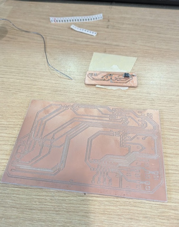
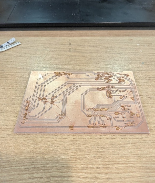
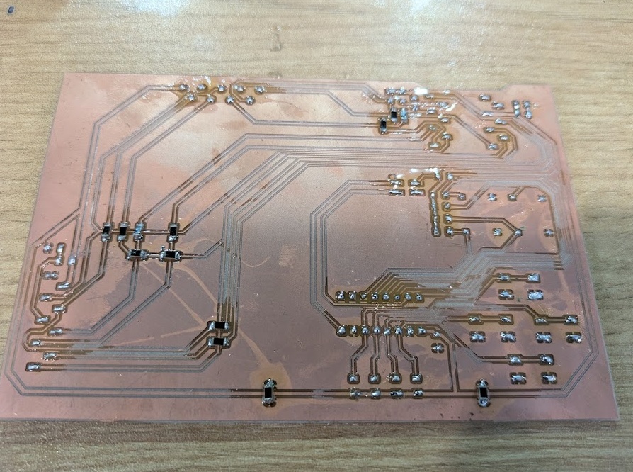
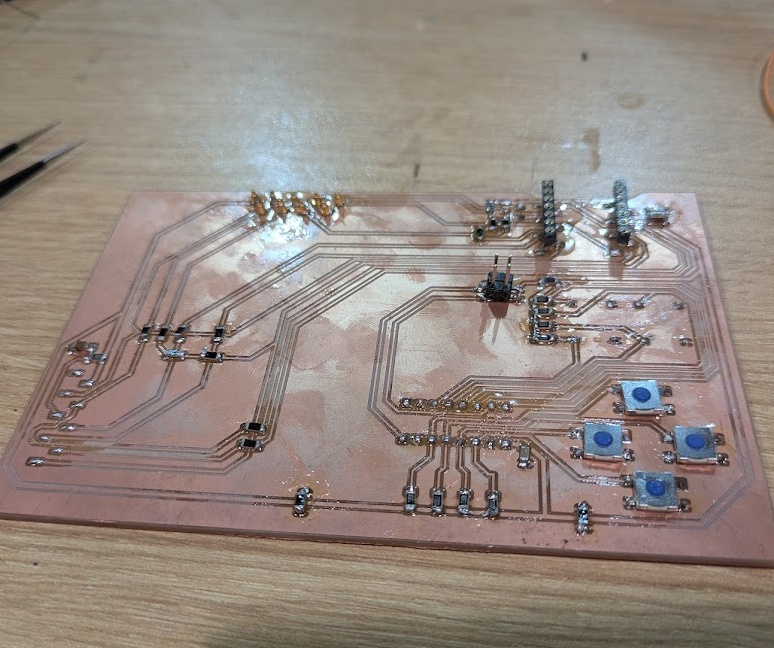
All that was left was to get some simple Circuit Python code cobbled together which was easy thanks to Adafruit's Resources.
import board
import digitalio
import time
import microcontroller


LATCH_PIN = microcontroller.pin.GPIO41
CLOCK_PIN = microcontroller.pin.GPIO39
DATA_PIN  = microcontroller.pin.GPIO40

latch = digitalio.DigitalInOut(LATCH_PIN)
latch.direction = digitalio.Direction.OUTPUT
latch.value = True

clock = digitalio.DigitalInOut(CLOCK_PIN)
clock.direction = digitalio.Direction.OUTPUT
clock.value = False


data = digitalio.DigitalInOut(DATA_PIN)
data.direction = digitalio.Direction.INPUT

button_names = [
    "A Button",
    "B Button",
    "Select",
    "Start",
    "D-Pad Down",
    "D-Pad Left",
    "D-Pad Right",
    "D-Pad Up"
]

last_pressed = []

while True:
    current_pressed = []

    #debounce
    latch.value = False
    latch.value = True

    for i in range(8):
        is_pressed = not data.value

        if is_pressed:
            current_pressed.append(button_names[i])

        clock.value = True
        clock.value = False

    if current_pressed != last_pressed:
        if current_pressed:
            print(f"Pressed: {', '.join(current_pressed)}")
        else:
            print("All buttons released.")

        last_pressed = current_pressed

    time.sleep(0.05)
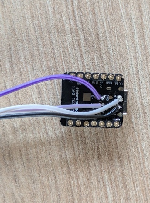
and then deploy it to the XIAO!
CARTRIDGE TESTS
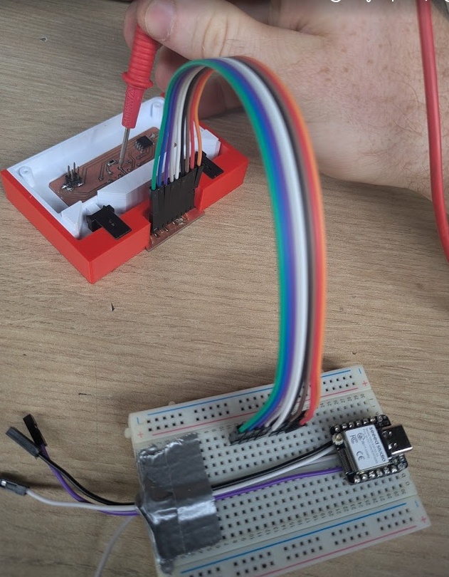
My final project utilizes individual cartridges to store each program's code (on W25Q128JVSIQ flash memory chips) but I'm also planning to support "expansion" cartridges that support additional functionality over a number of reserved pins. I used this week to start testing the functionality and practicality of running different interfaces over the pins connecting the PAK to each cartridge. This preliminary testing helped me learn a lot about what considerations I needed to make for my next prototype build. My original plan was to just reserve an I2C-SDA and I2C-SCL line for any expansion, but after some digging into specifications and learning about how data would need to be transmitted, I think I'm going to need more than just 9 pins for the final design.
You can read more about the actual ideation and prototyping process on my final project page., but in a nutshell, this week was about trying to test a system that would allow me to, in theory, install an "external" input or output device, and have it communicate to the XIAO explicitly through the cartridge pins.
Another nifty thing I'm planning on working into the cartridge is an "identification resistor" that the PAK can detect almost instantly as soon as a cartridge is inserted. Each cartridge has it's own resistor value (e.g. 1K, 4.7K, 10K, 47K, etc.) that will have it's assignment coded in the OS of the PAK. This is so the PAK can respond quickly to a new cartridge being inserted, rather than having to wait for all of the data to be schlept off the cartridge and into the PAK's RAM. It won't really save any time for that, but it let's us play a cute little animation or load in specific libraries for the cart we're about to use. More to come as I figure this one out!
➔ Accelerometer
I wanted to start with a device that natively speaks I2C for my cartridge testing, so I picked up one of the few boards I actually brought with me from Canada, a MPU6050 accelerometer. I had absolutely no issues getting talking to the XIAO over my cartridge. All I needed to do was run connect the SDA and SCK lines directly to the dedicated I2C lines I developed on my cartridge and then flash some code on to the XIAO.
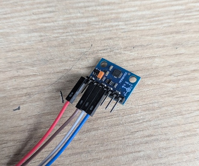
I first created some code to just read the values from the I2C, but displaying them in the Terminal as raw values didn't really communicate to me the full picture of what the sensor was reading. So I added a little bit of code to visualize the numbers in a "progress bar + bubble" kind of output, where values from the accelerometer are mapped (translated from the raw voltage values to positions on a -1 to 1 number line) for each of the 3 axes.
import busio
import microcontroller
import time

print("Accelerometer Test")

i2c = busio.I2C(scl=microcontroller.pin.GPIO6, sda=microcontroller.pin.GPIO5)
i2c.try_lock()

addresses = i2c.scan()
if not addresses:
    print("ERROR, NO I2C")
    i2c.unlock()
    while True: pass

MMA8452Q_ADDR = addresses[0]
print(f"found at 0x{MMA8452Q_ADDR:02X}")
i2c.writeto(MMA8452Q_ADDR, bytes([0x2A, 0x01]))
time.sleep(0.1)

buffer = bytearray(6)

def convert_12bit(msb, lsb):
    val = (msb << 8 | lsb) >> 4
    if val > 2047:
        val -= 4096
    return val / 1024.0

def draw_bubble(val, width=30):
    # Clamp and map
    val = max(-1.0, min(1.0, val))
    pos = int((val + 1.0) / 2.0 * width)
    track = ['-'] * (width + 1)
    track[width // 2] = '+'
    track[pos] = 'O'

    return "".join(track)

try:
    while True:
        i2c.writeto_then_readfrom(MMA8452Q_ADDR, bytes([0x01]), buffer)

        x_g = convert_12bit(buffer[0], buffer[1])
        y_g = convert_12bit(buffer[2], buffer[3])
        z_g = convert_12bit(buffer[4], buffer[5])

        x_bar = draw_bubble(x_g)
        y_bar = draw_bubble(y_g)
        z_bar = draw_bubble(z_g)

        print(f"\rX [{x_bar}] {x_g:5.2f}G | Y [{y_bar}] {y_g:5.2f}G | Z [{z_bar}] {z_g:5.2f}G", end="")

        time.sleep(0.05)

finally:
    i2c.unlock()
➔ Rotary Encoder
One of the ideas I had for a cartridge for the PAK was a game that utilized a rotary encoder as one of the main inputs. The encoder itself would be baked into the cartridge, and send it's data over the I2C lines. However, it was here that I realized that a little rotary encoder wasn't going to just speak I2C without extra onboard processing, something I wanted to avoid to keep cartridge manufacturing cost down. If I wanted to include non-I2C ready devices on cartridges, I would need to opt for a cartridge design that included more reserved pins, for different kinds of inputs and outputs. For this specific test, I just decided to hijack the I2C lines, remove the 4.7K Ohm Pull-Up resistors on the XIAO's end, and treat these two lines like any other GPIO lines.
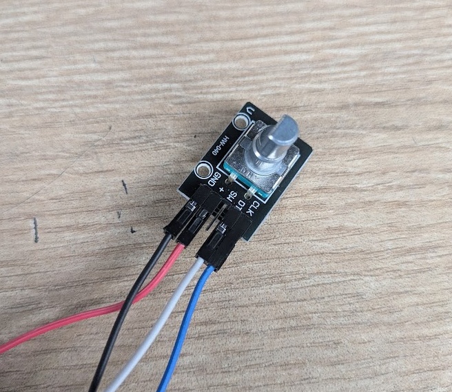
The rotary encoder works by outputting a quadrature signal (hold up, don't leave just yet, I'm going to explain!). Inside of the encoder, there is a conductive disc with gaps in it and two metal wipers (we'll call them A and B) that are spaced apart and complete their own circuits with the metal disc. If you spin the encoder clockwise, wiper A hits the metal first, followed by wiper B if you continue rotating. If you spin it the other way, wiper B hits first followed by wiper A. It's called a Quadrature signal because there are 4 possible states for A and B to be in together: (0,0), (1,0), (0,1) and (1,1). Repeating the spinning motion and subsequent contact pin-to-plate contact allows you to determine (using code) which way your encoder is traveling and how many "ticks" it has traveled.
Writing the code for it was quite trivial, as Circuit Python already has a library that handles this square wave signal. All I needed to do was call the encoder position, and then I could manipulate how that number was displayed in the Terminal. I opted to have the XIAO poll the encoder every 0.01 seconds and only print a new line in the terminal if the encoder position had changed. I could then do some simple comparison to determine if the encoder was rotating clockwise (values would increase) or counterclockwise (values would decrease).
import microcontroller
import rotaryio
import time

print("Rotary Encoder")

encoder = rotaryio.IncrementalEncoder(microcontroller.pin.GPIO5, microcontroller.pin.GPIO6)

#init pos
last_position = encoder.position

while True:
    # current pos
    current_position = encoder.position

    if current_position != last_position:
        if current_position > last_position:
            direction = "Clockwise  -> "
        else:
            direction = "Counterclockwise <- "

        print(f"{direction} Current Position: {current_position}")

        # update pos
        last_position = current_position

    time.sleep(0.01)
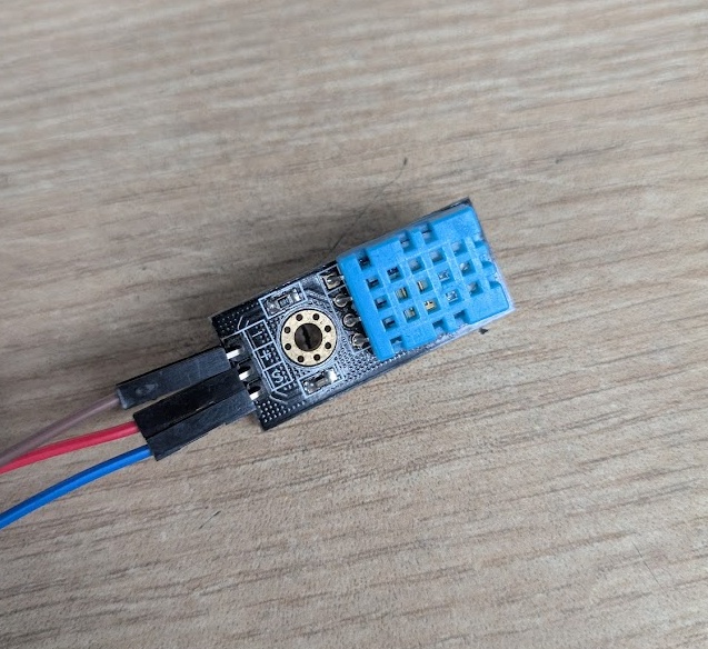
➔ Temperature and Humidity Sensor
Another application that I could develop as a cartridge could be a Weather "app" that not only reads your ambient weather via temperature sensor, but can also pull data from the internet to show you the forecast for your area.
I would again, need to hijack my cartridges supposedly dedicated I2C lines in order to send the data from this sensor. Luckily, this sensor only uses a single signal pin. The DHT11 is a "smart" sensor that has it's own microprocessor onboard and an analog to digital converter. It's able to output that digital signal that we spoke about earlier in the GPIO section on it's own.
The code uses the Adafruit DHT device library, and much like the encoder above, can be read with a simple call of the temperature and humidity objects. I could have this data just printed raw in the Terminal, though for sensors like these, it's a good idea for you to calibrate them by determining if what they are outputting matches what is output by another sensor that you know is reliable. To do this, take 2-3 measurements on both sensors and plot them to see if the relationship is linear, and if it is, you just need to modify the y-intercept to get the data points to line up.
import time
import microcontroller
import adafruit_dht

time.sleep(1)
dht_device = adafruit_dht.DHT11(microcontroller.pin.GPIO5)


prev_temp = None
prev_hum = None

while True:
    try:
        temp_c = dht_device.temperature
        humidity = dht_device.humidity

        if prev_temp is not None and prev_hum is not None:
            temp_change = temp_c - prev_temp
            hum_change = humidity - prev_hum

            temp_display = f"{temp_c:.1f}°C ({temp_change:+.1f})"
            hum_display = f"{humidity:.1f}% ({hum_change:+.1f})"
        else:
            #first loop
            temp_display = f"{temp_c:.1f}°C (---)"
            hum_display = f"{humidity:.1f}% (---)"

        prev_temp = temp_c
        prev_hum = humidity

        print(f"\rTemp: {temp_display}  |  Humidity: {hum_display}          ", end="")

    except RuntimeError as error:
        print(f"\rReading sensor... ", end="")
        time.sleep(2.0)
        continue

    except Exception as error:
        dht_device.exit()
        raise error

    time.sleep(3.0)
Conclusion
It feels like I’ve finally started bridging the gap between making things work on a breadboard (and all of my amateur bodges in electronics over the years) to actually engineering a consumer-grade functional system.
The shift register board was the heavy lifter here, and while it felt great to see those buttons register correctly on the first go, the real value came from all of the things I learned trying to test out PCBs for my final project. Upsetting as it was, I really learned a lot about PCB design, so many do's and don'ts that you can really only learn through experience, and of course the importance of patience (i.e. doing it right the first time).
It became pretty obvious that relying solely on I2C is a bit of a trap if I want the PAK to be truly modular with it's cartridges. Having to manually pull resistors and hijack lines for the encoder and DHT11 showed me that my initial 9-pin connector is just too restrictive for what I have in mind. In the future, I’d definitely spend more time mapping out a universal pinout that doesn't require these kinds of hardware hacks to function. That said, I'm proud of the simulations I created (with the help of Gemini) - I hope others stumble upon them and use them to teach or learn! Maybe I will compile them all on a single page when I'm finished up at Fab Academy this year.