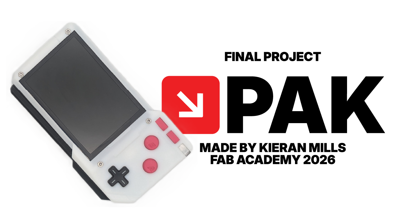
ABOUT THE PAK
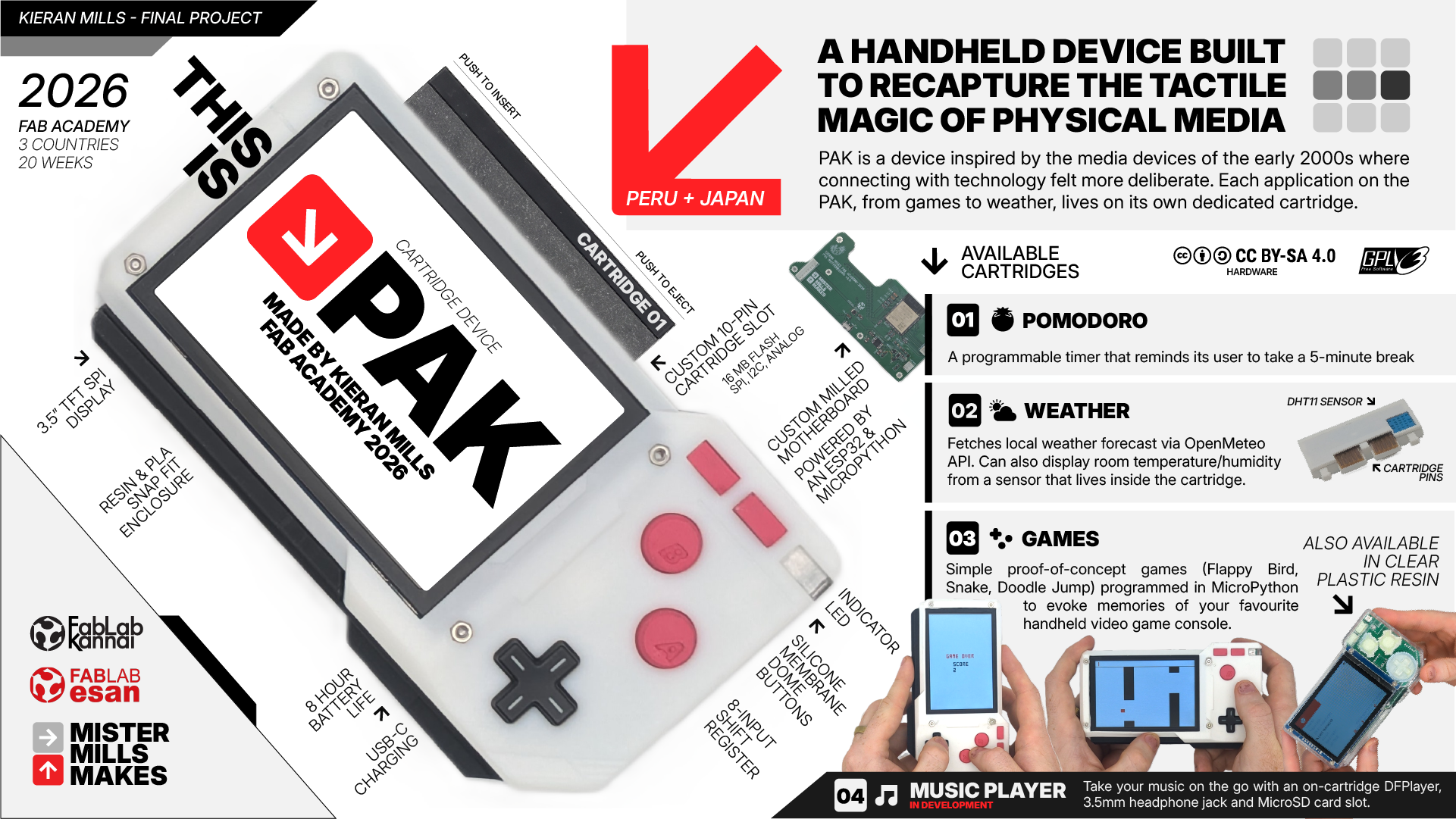
PAK is a handheld 'dumb' device designed to restore intentionality and satisfaction to our every day devices. In an age of multitasking, this device does the opposite: it is a modular host where every application lives on its own physical cartridge. The concept is simple: One app equals one cartridge. If you want to take notes, you insert the Notes cartridge. If you want to take a photo, you swap it for the Camera module. The device reintroduces the tactile joy of physical media (the satisfying click of a cartridge) and the deliberate act of powering something up and using it with your full attention. No notifications, no distractions. Just the satisfying tactile experience of a device that does one thing at a time, intentionally.
CARTRIDGES
Each cartridge is its own application, and development on each is tracked independently on top of the system software that runs the PAK's "operating system". In order of development, we have:

POMODORO
A simple timer/countdown cartridge that reminds the user to take a 5 minute break every 40 minutes.

WEATHER
Uses the ESP32's Wifi Connection to make an API call to Open Meteo, also uses an onboard DHT11 temperature and humidity sensor to poll the ambient temperature.

GAMES
Simple interactive games (really, proof-of-concept, I didn't have the time to game design from the ground up) coded natively for the PAK's custom operating system, such as Doodle Jump, Snake, and Flappy Bird.

MUSIC PLAYER
Currently in development. Utilizes a DHplayer and 3.5mm headphone jack to play music from a cartridge embedded microSD card.
HOW I MADE IT
The PAK was the summation of my 20-week journey in the Fab Academy 2026. You can follow my journey of each of my individual assignments by following the links found throughout this site, but if you're curious as to how I actually pieced this device together over the weeks, below is a detailed log of my prototyping, my research, and all of the little rabbit holes I found myself digging in over the course of 5 months. In the Fab Academy, we're encouraged to develop in "spirals", that is, to complete a simple form of the product first and then develop improvements around it, instead of trying to build the full thing from the get go. The first half of my Fab Academy journey was largely working through micro spiral developments of each of the sub-systems employed by the PAK, and then over the second half of the course, learning how to piece it all together.
AI DISCLAIMER
As an educator, I believe LLMs are a terrific tool to help us with learning but it's important that we do not let it take over our agency in producing the things we want to make as learners.

Throughout Fab Academy, I utilized Google's Gemini to help me through my learning as a conversation partner, soundboard, and expert debugger. I used Gemini to help me think through ideas, concepts, and gain a deeper understanding of the many different fields we cover in this 20-week whirlwind. For all of my assignments and work on the PAK, I would always start by trying things out myself first and, for lack of a better term, banging my head against the table to understand what it was I was trying to make. I would have lengthy conversations with Gemini to build my understanding and confidence. I primarily code in MicroPython for my final project, and would ask Gemini to assist me with understanding the best way to structure functions and classes, and help me with debugging errors and optimization. Unless otherwise stated, the work presented here is 100% my own. Designs, sketches, diagrams and renders are 100% human made.
PLANNING
The first half of Fab Academy was spent prototyping small parts and individual mechanisms of the PAK. You can see what I focused on in each week below.
In the months leading up to Fab Academy, words from one of my first meetings with my mentor Jorge at ESAN kept playing back in my head. He said to me that the best way to be successful in the course is to have a final project idea for the first week of classes. This tormented me for weeks, I had such a hard time coming to terms with the commitment. I quite literally had dozens of projects and things I wanted to explore, how could I pick just one?
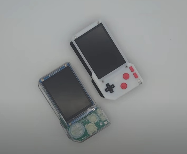
What I'm sharing with you today ultimately comes back to the object that got me into tech in the first place: an original purple Game Boy Advance, my first personal device. I've always been fascinated by consumer electronics and the design language of the big names in the industry: Braun, Nintendo, Sony, Teenage Engineering.
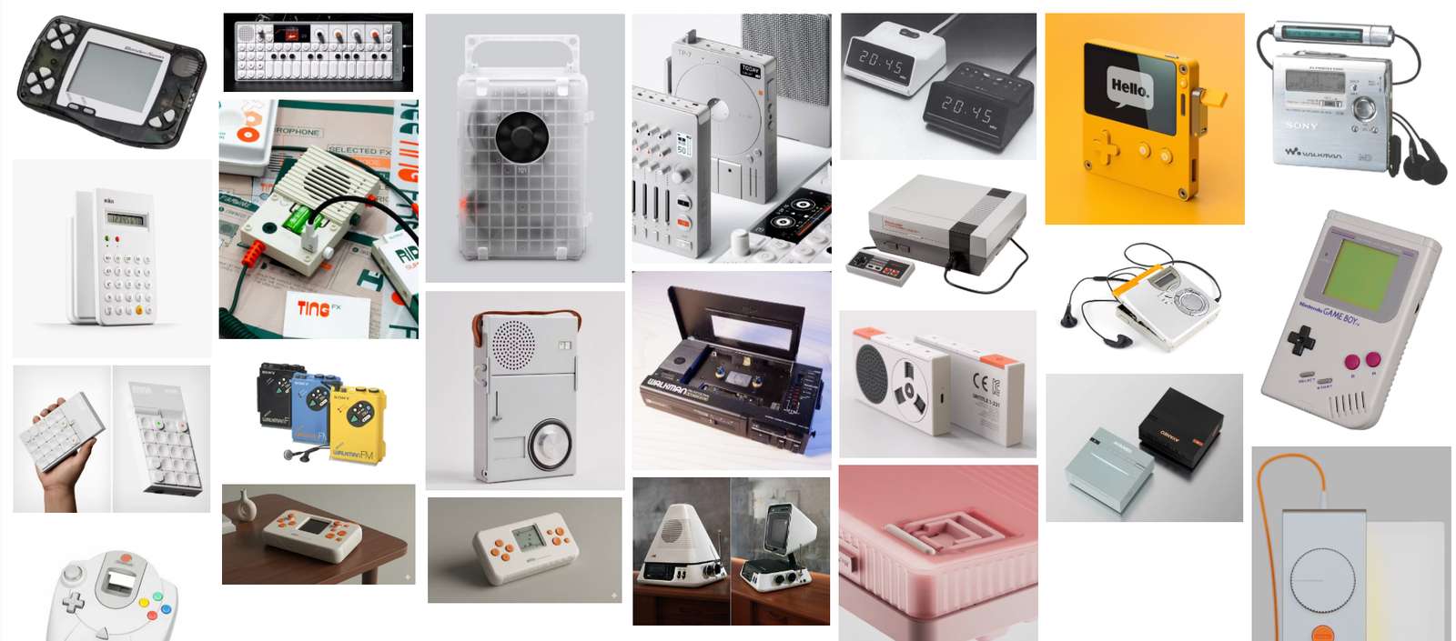
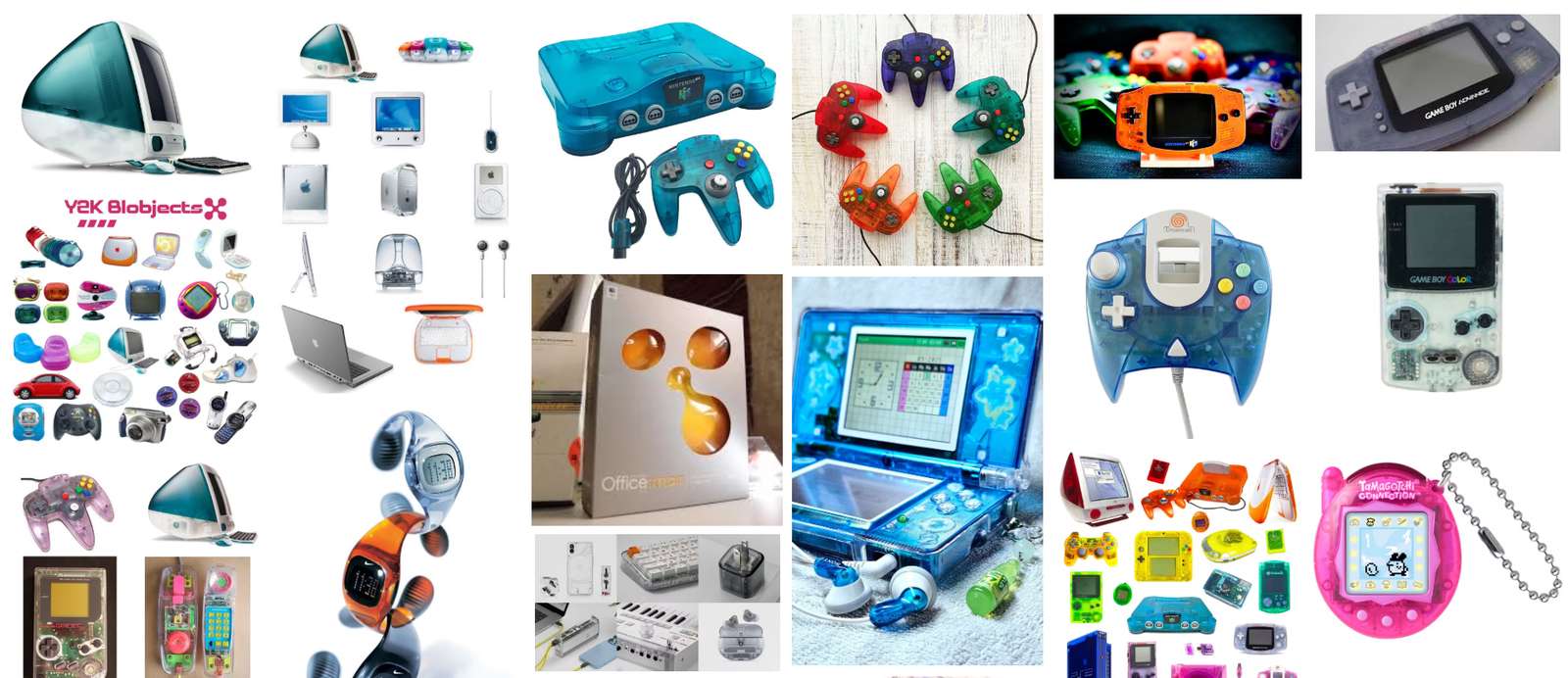
I'm also drawn to the aesthetics of the early 2000s (having a strong sense of nostalgia for that world), and would be interested in designing devices that call upon the "blobject" and "frutiger aero" design language of this idyllic world that we have all left behind for less green pastures.
I've tried creating my own very simple 3D-printed electronics enclosures and have created simple circuits by repurposing existing logic boards and utilizing commercial boards, but the Fab Academy is going to give me an opportunity to push this understanding and learn more.
I also wanted to center my project around a problem, as any good designer does. Look for a problem, not a solution. As a high school teacher, I am no stranger to the impact that cell phones have had on attention spans, focus, and our abilities to be comfortable being bored. Using the internet and a cellphone is a near requirement for participation in society these days, and the creators of these devices and the software that powers them do not have our wellbeing in mind when their design prioritizes increasing engagement and data collection above all else.
Enter, my final project idea:
FINAL PROJECT IDEA, JANUARY 2026
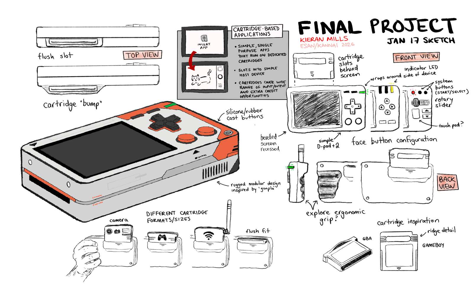
This is a handheld device meant to replace your smartphone but still give you access to important features needed for modern life. The catch is that each of the features exists on it's own dedicated cartridge, much like a single game can only occupy one Game Boy Advance cartridge. Swapping "apps" is a deliberate action the user must take. The intended user is someone who wishes to "unplug" from the modern world of electronics and return to a time that humans used technology with intention, not compulsion.
Your first impression may be that this sounds overly ambitious, and I agree. But the development of the device and the added cartridges are meant to be spiralled into bits and pieces that be developed independently, and I can have a minimum viable product with many stretch goals. My primary goal with this device is to create a simple handheld computer that I have created the enclosure, custom PCB and software for, with one cartridge that runs a simple program.
Towards the end of my sketching, I started playing with the idea of a third design language that I've been interested in, and one that ultimately was the inspiration for the stylesheet for this website.
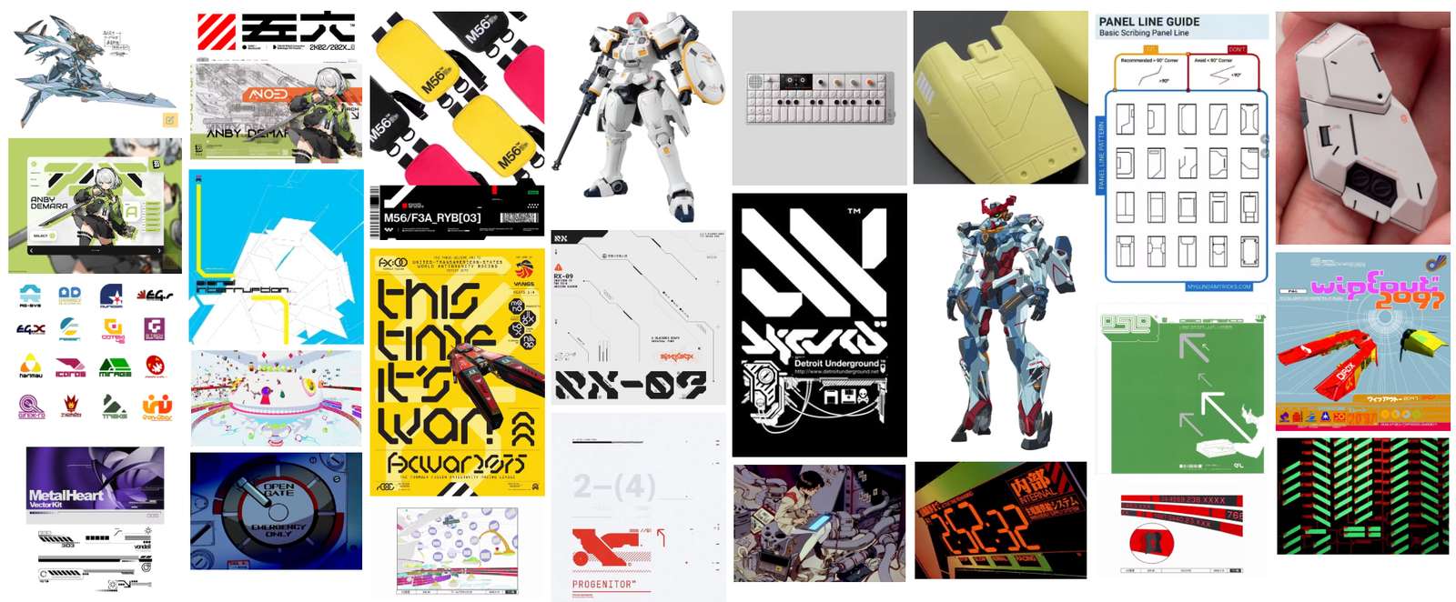
There are not a lot of words to describe this aesthetic. I tend to default to the Consumer Aesthetics Research Institute (CARI) when it comes to vocab. The site describes this look as: Vectorheart, characterized by "futuristic forms" and "high-contrast typography that borrows from both Swiss modernism and utilitarian industrial design".
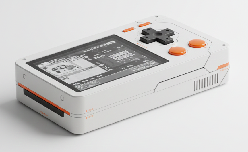
I had an idea to run my sketches through Gemini's Nano Banana image generator to see what it could create.
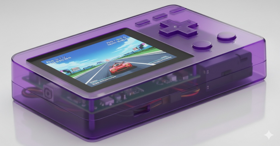
and for fun, I asked it to try out the same render in clear plastic, a la Y2K.
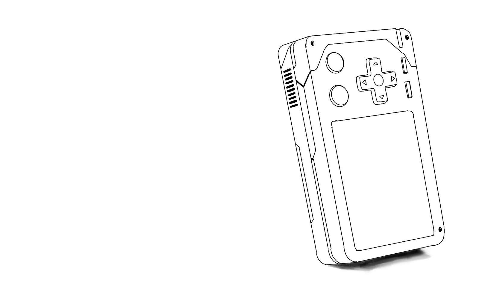
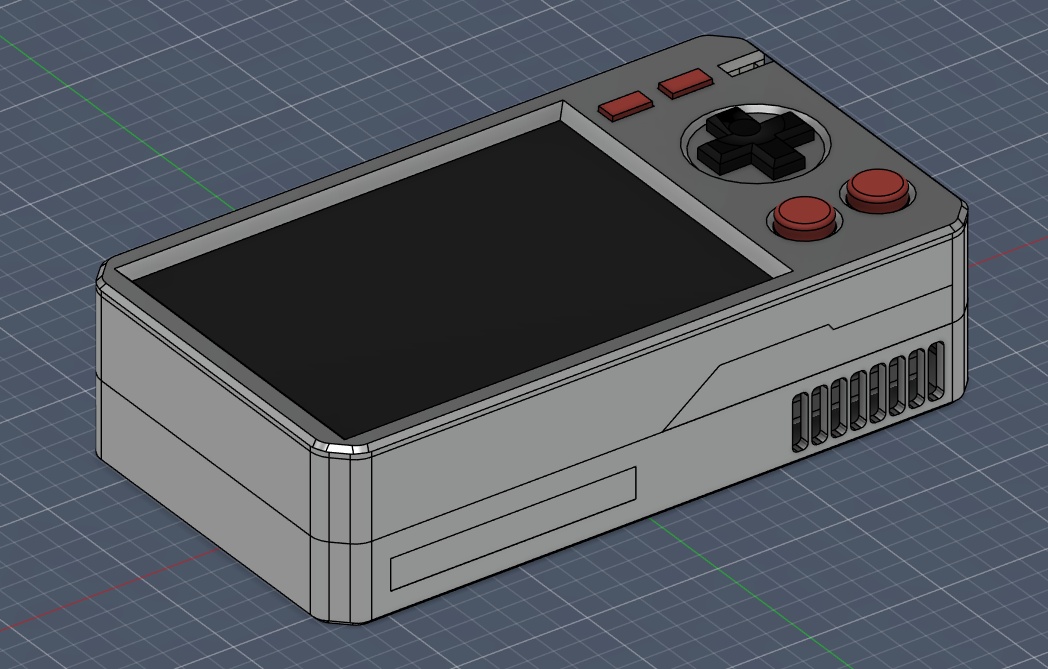
I knew that for my first iteration of my device (which is still unnamed) I would want to start with a simple enclosure, without trying to over-complicate things to start. I knew roughly that I wanted the device to fit nicely in a pocket, and comfortably in one hand (hence why all of the controls are on one side). The user is meant to hold the device like a point and shoot camera, not a game console (despite the appearance haha).
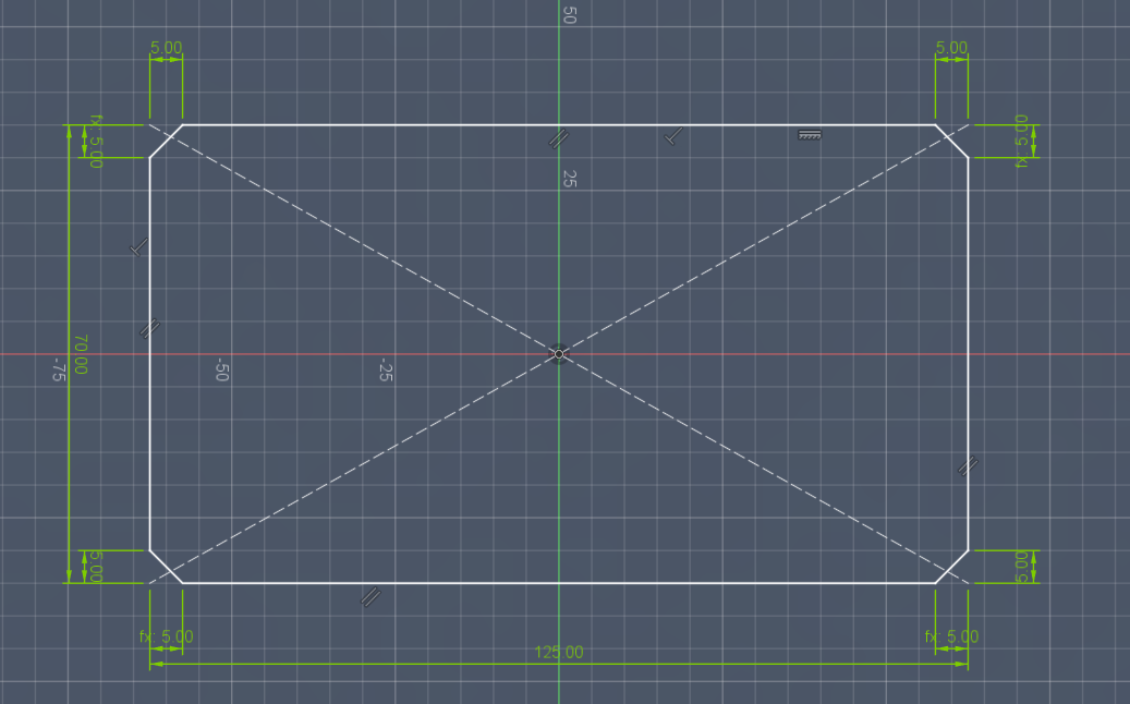
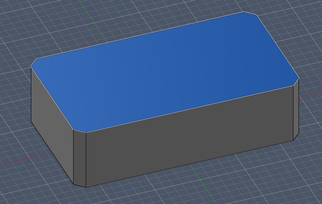
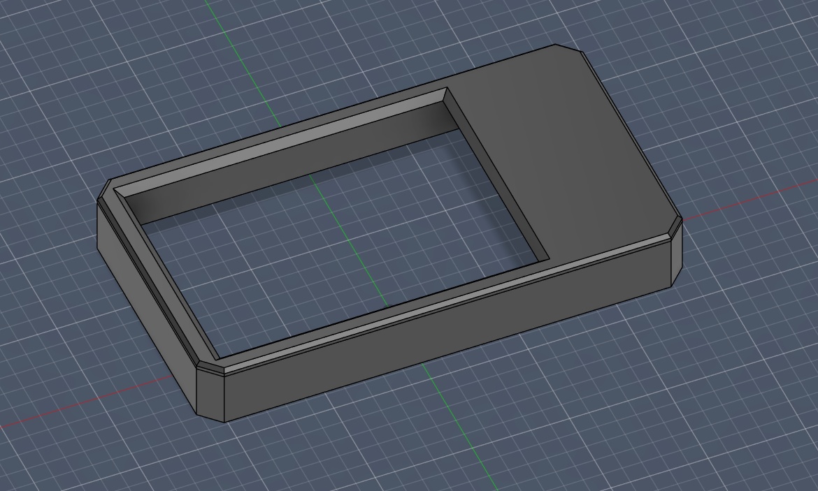
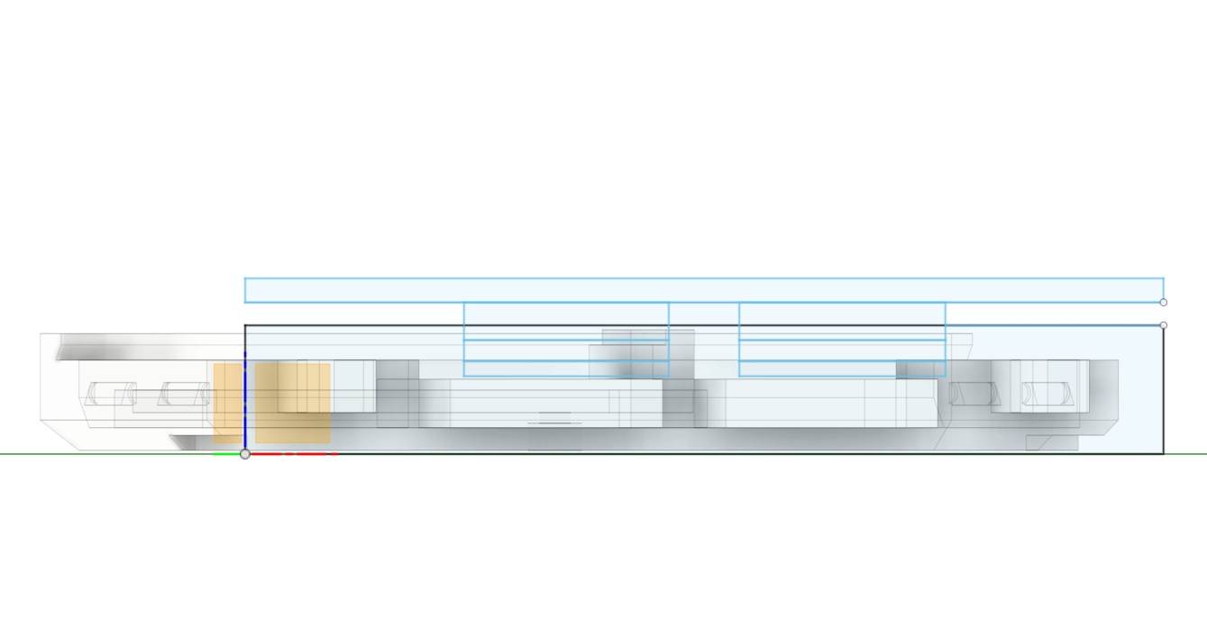
I started out with a simple rectangular shell (dimensions can be found above), and carved out the space for the screen. I added a simple chamfer to the edges of the device and a bevel to the screen.
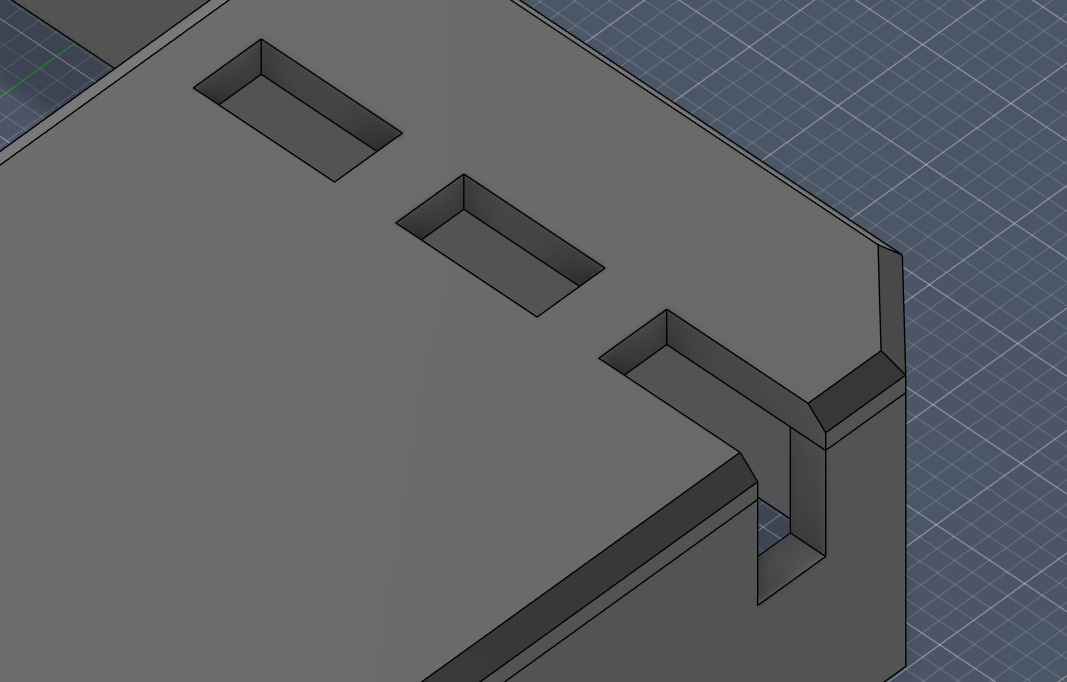
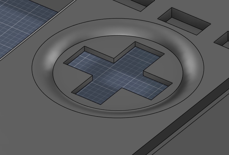
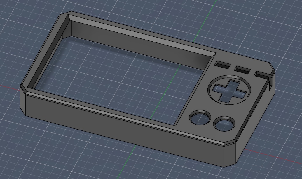
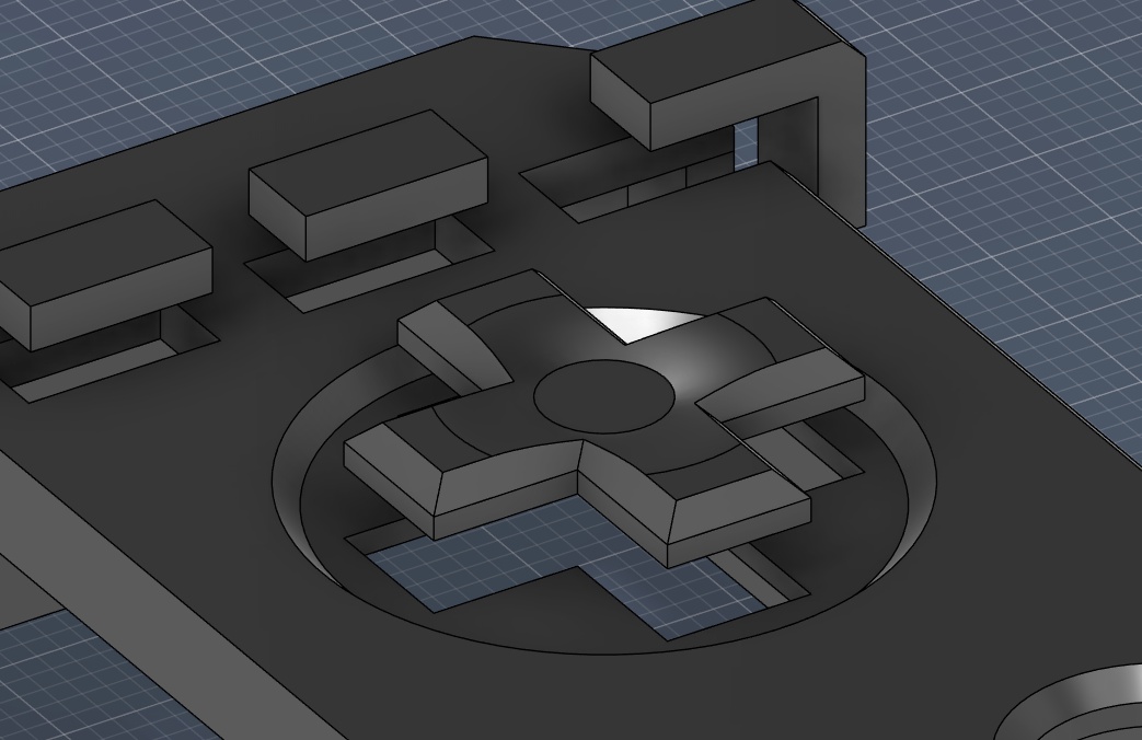
Using additional sketches on top of the top face of the main body, I started playing with shapes for the buttons and added electronics. Since I don't know what my final design will incorporate, I just used dimensions that felt right for placeholders. The beauty of parametric design is that I can easily come back and edit the numbers to fit different parts.
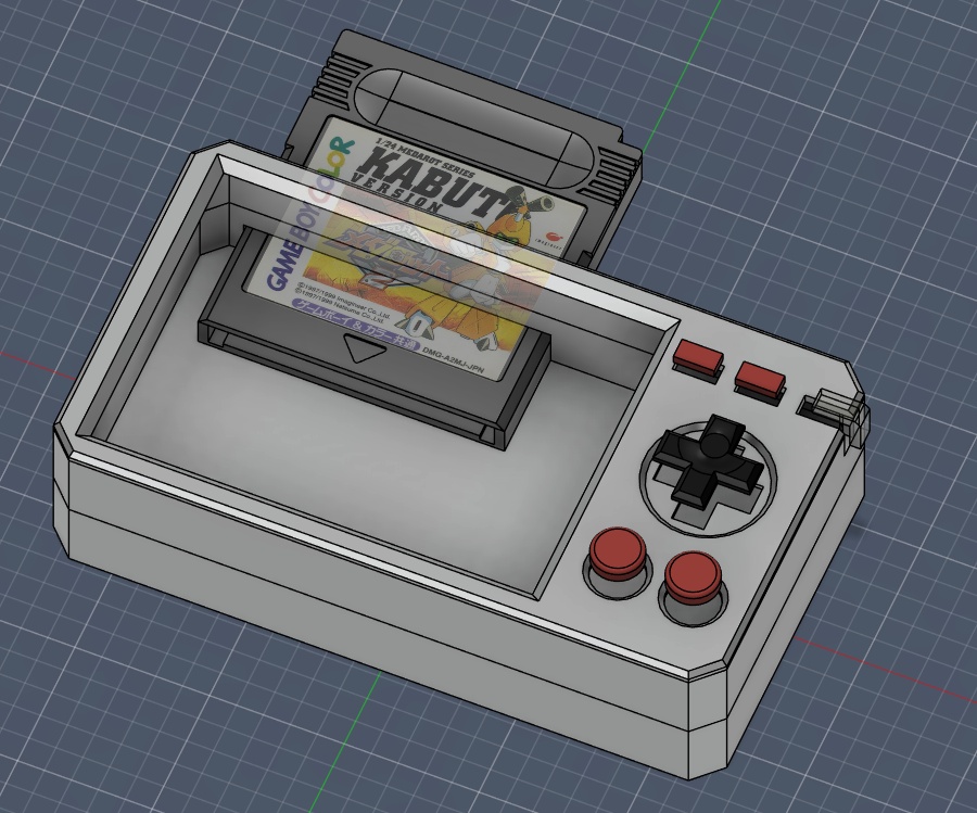
Since I also needed to revisit what the final cartridge design would be later, I decided to just import the Game Boy cartridge I modelled earlier as a placeholder. I intend to iterate on the design of the cartridge and make it something that better fits the aesthetic, form and function of the device. I was telling my mentor, Jorge, that I think one of the most important parts of the cartridge and device is getting the tolerance spot on for that perfect insertion feel.
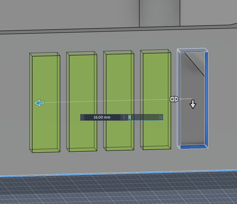
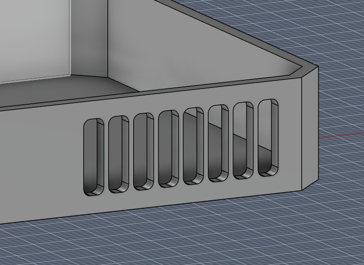
Once I had a good starting place with the shell, I decided to try adding some surface motifs, like small vent holes, detailing lines, additional fillets to the corners for comfort. All things I want to iterate with once I'm able to start 3D printing prototypes.
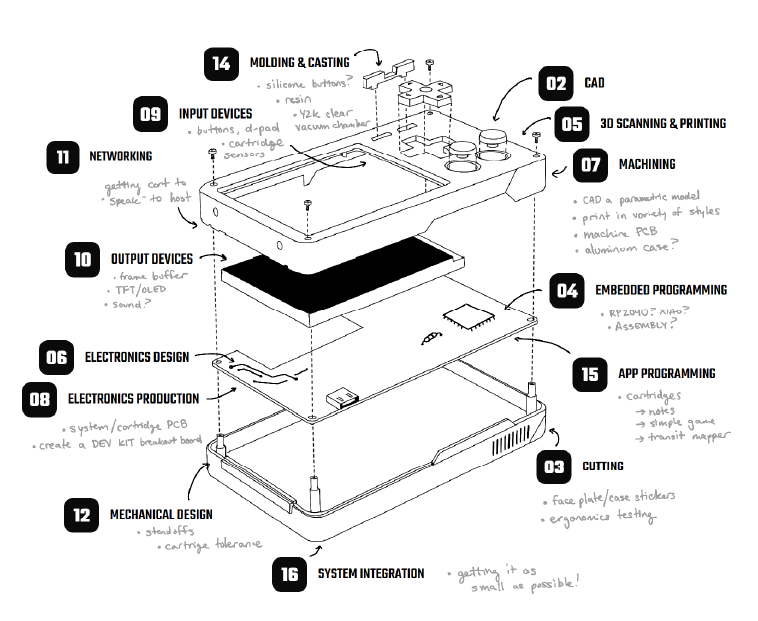
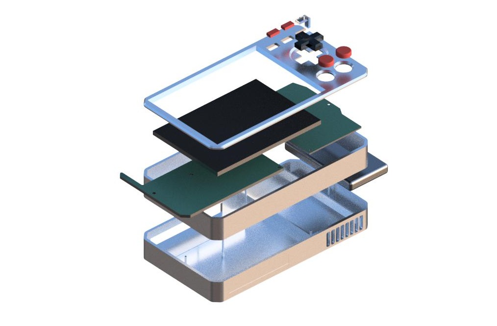
I even went so far as creating placeholder internal components, like PCBs, a LiPo battery and screen. Obviously all TBD, but it allowed me to render out this terrific expanded view, and the animation that can be see as the (header for week 02)[./assignments/week02.html].
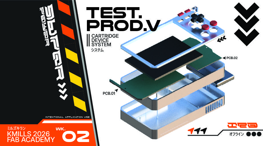
This was also a great opportunity to create some "promotional" material using my Illustrator skills. I created this image using some of the vector motifs I designed - which, unfortunately does not stand the test of my photo compression script. Perhaps I can use some kind of hybrid .svg and raster format for presenting my work. I would like to preserve that super clean minimalist high-contrast look.
SUB-SYSTEM PROTOTYPING
To get to the first working version of the PAK, we need to test and iterate each of the individual sub-systems, like the screen, the controls, the cartridge slot, etc. I tried to match each week's course content with something I could prototype or test (or really just learn more about). You can see each of the week numbers on the left side and what I tried testing as the title of each drop down. These tests are ways to help me learn what to do and what not to do for the next spiral!
As of April 23rd, 2026, the PAK has taken shape into its first prototype form, with all bells and whistles in tact. It's not pretty, but almost everything that will be in the final build is there on a fundamental level, and most importantly it works.
I wanted to take the opportunity this week to explore my options for the PAK's architecture. After doing a bit of reading and testing, I determined that the RP2350 would be the best fit for the PAK's main driver.
My main focus this week was to become a bit more familiar with developing for the RP2350 and slowly start to develop the actual development process for creating future PAK cartridges on the chip. I decided that, in place of a traditional app launcher (reminder that the PAK has no built in apps), I wanted a little character to be shown on the screen, and it could react to the user's inputs, animating when the user presses buttons or even inserts a PAK into the system!
Since I didn't have the full screen I wanted to use yet, I figured I would start develop a placeholder, or at least something that I could scale up to other device sizes.
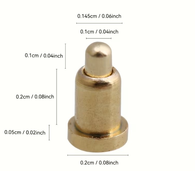
This week I wanted to start actually fleshing out the design and shape of both the PAK itself and the cartridges that would interface with it. After some earlier thinking, I decided that the best interface for the cartridges to the main unit would be through the use of spring loaded POGO pins, so I placed an order at the end of last week for a pack of 100. In the meantime, I could start thinking about how they would interface with the plastics. This would be design consideration #1.
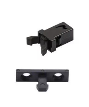
Design consideration #2 would be to determine how I want the cartridges themselves to interface with the unit. I could opt for a friction fit akin to the Game Boy or home consoles like the SNES or N64, or I could opt for a push-push latch mechanism that feels a bit more luxurious and secure akin to a microSD card or Nintendo DS/3DS cartridge.
I found this 3D printable spring push-push mechanism on Makerworld that I thought would be a good start. It utilizes a heart shaped track/cam that allows a pin to travel in one direction around the path, preventing the spring from debouncing once pressed in.
The spring mechanism is one thing but I would also need to envision away to "latch" the cartridge in place. There's a great video by Engineezy that shows how the mechanism for microSD cards works that I took inspiration from.
After some failed prints and further frustration with trying to wrap my head around how this mechanism would work, I attended the Global Open Time on Saturday and Saheen recommended to me a part I could order that would make my life much easier rather than trying to 3D print micro compliant mechanisms.
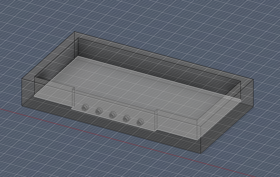
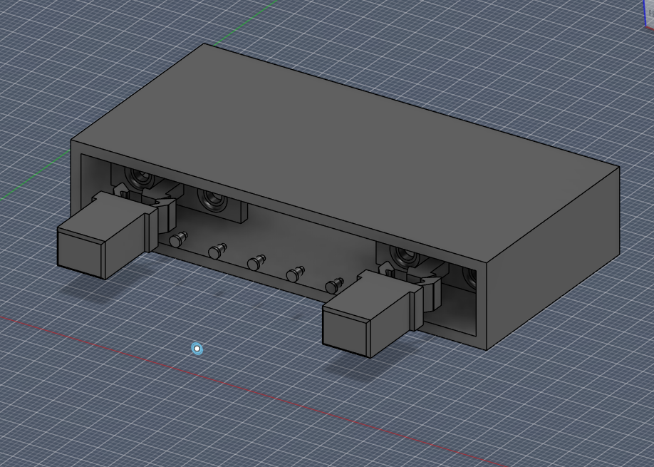
Design consideration #3 was to engineer a way that restricts the user from inserting the cartridge the wrong way (and thus shorting or messing with the pogo pin wiring). To do this I would take a page out of Nintendo's book with their Game Boy cartridge design. It has a chamfer on two edges of the same face that is complimented by a guiding "rail" inside the slot. Try to put it in the other way and you'll find the cartridge doesn't fit.
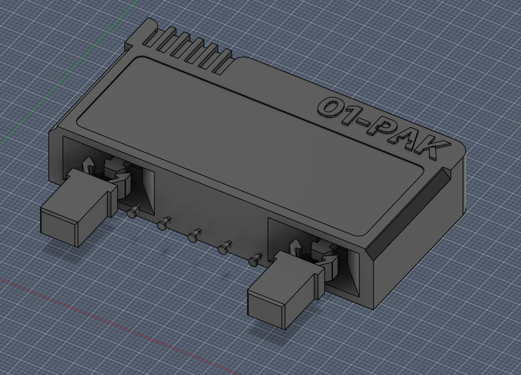
This was a great start to developing the actual shell to the device. I finally have one constraint to work around (although, the cartridge itself could still change sizes), so I can at least start with dimensioning out a PCB for the cartridge and perhaps the main unit next week and then continue iterating on the full shape of the case. I will say that I think the final unit itself needs to be fabricated with something a bit more fancy that PLA or ABS. I did like the way the resin print came out, so it's something to consider, but at least I have a good tool for rapid prototyping.
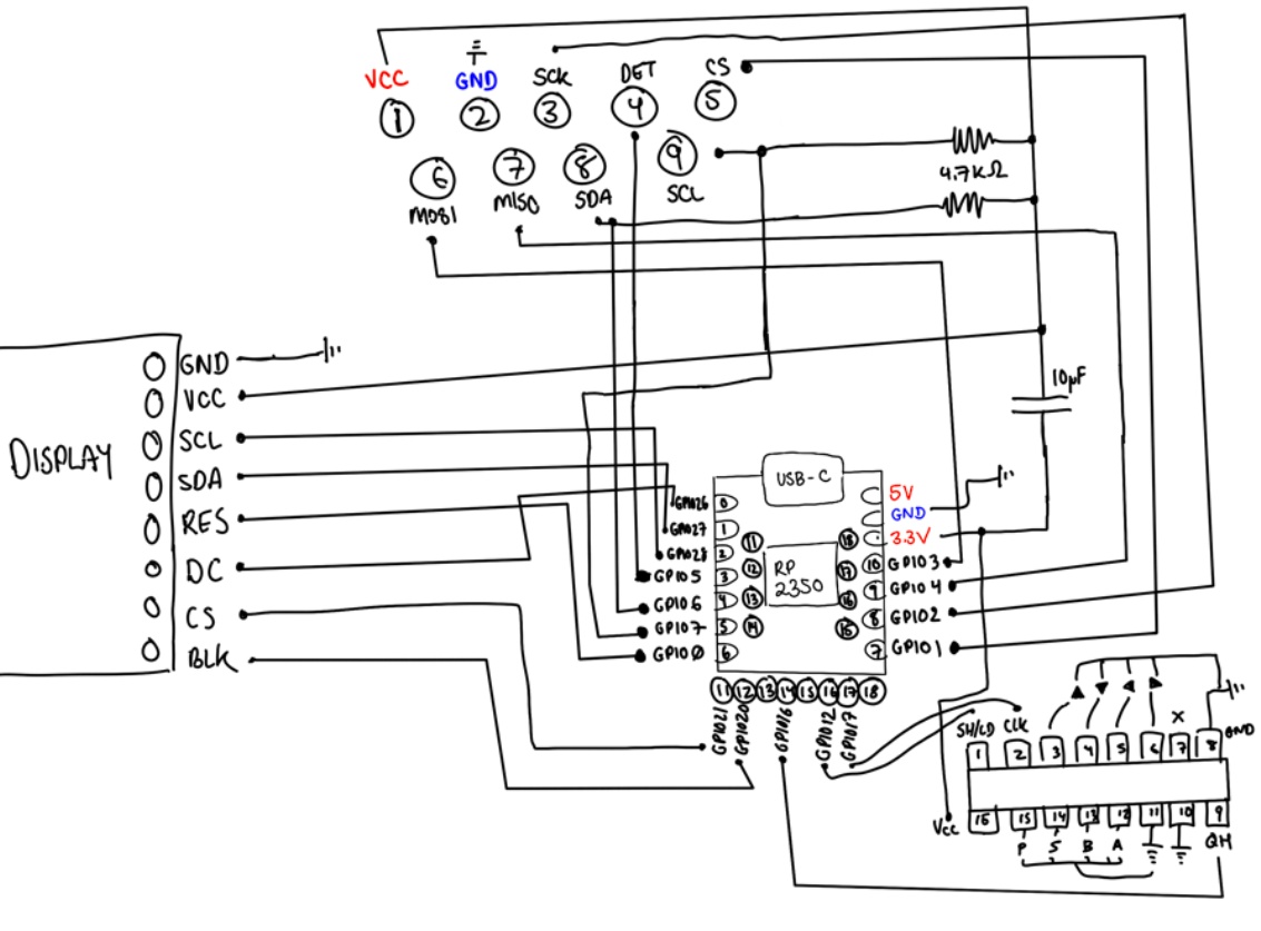
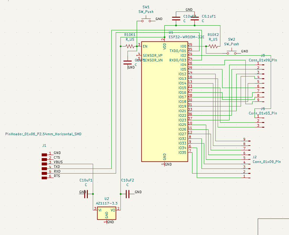
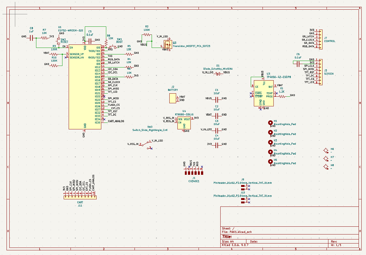
A key design decision made this week was the implementation of a dual-protocol bus for the cartridge, instead of picking either SPI or I2C, I chose to develop a system that could accommodate both as a future proofing method. The W25Q16 Flash IC that will store each cartridges software will communicate with the PAK via SPI (Clock, MOSI, MISO, CS) using a 7-pin configuration. I also chose to include an integrated I2C (SDA, SCL) line on pins 8 and 9 to allow for future "Hardware Apps." Once I've created the first simple cartridge (likely the Pomodoro app), I want to develop cartridges with more I/O functionality that isn't present on the main board. A single cartridge could house a camera module, a DAC for high-fidelity audio, or environmental sensors, all sharing the same two I2C pins.
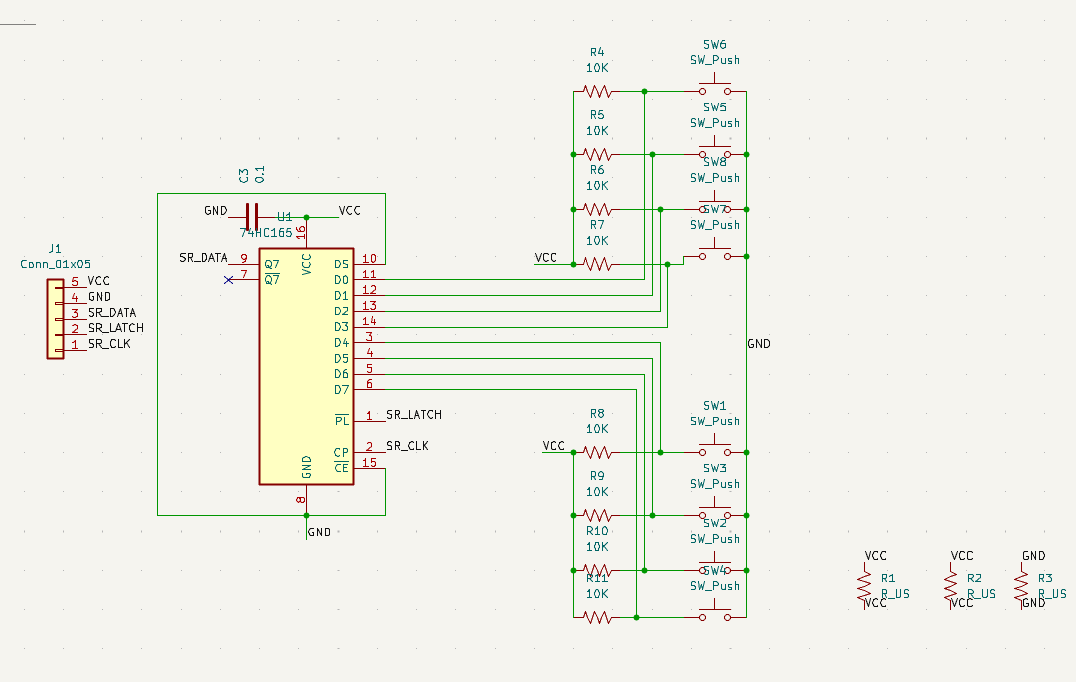
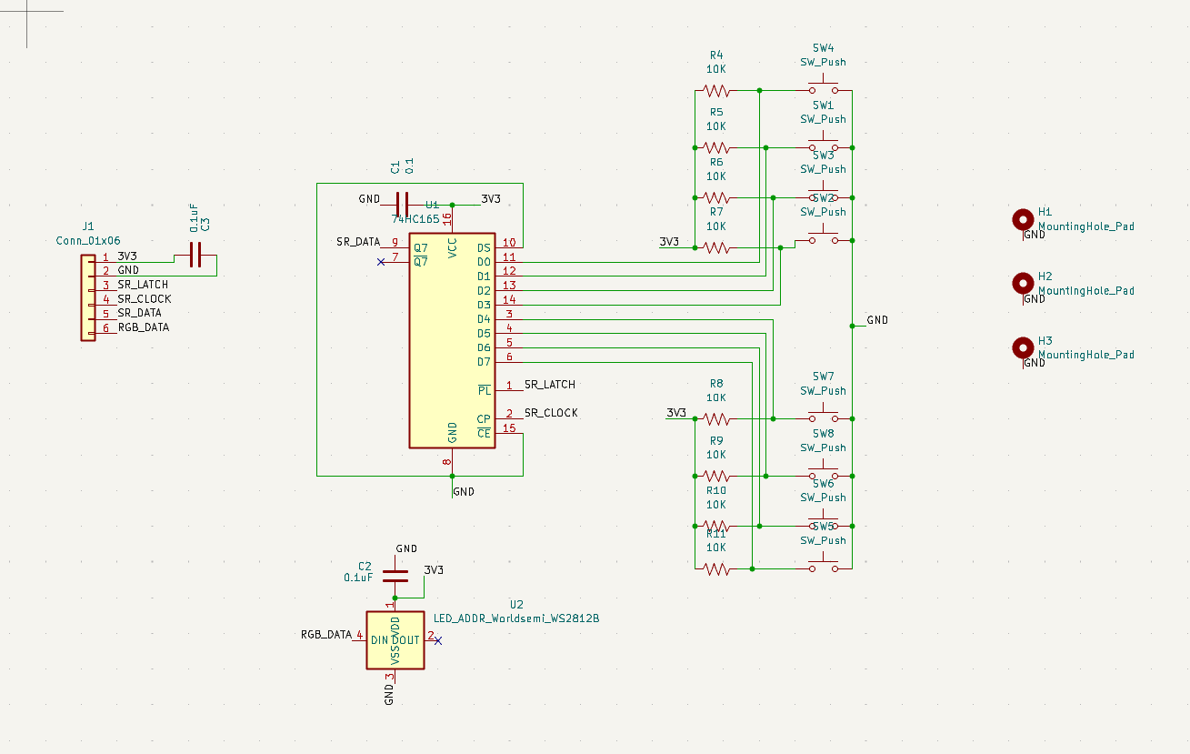
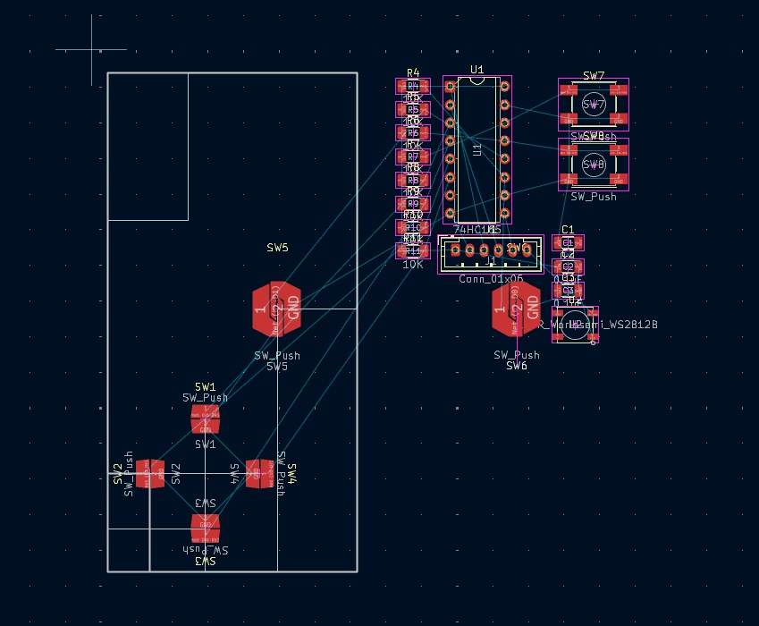
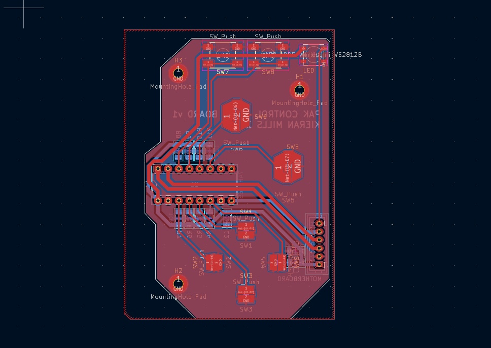
The PAK will also feature a D-PAD and 4 face buttons (A, B, START, and a fourth button I'm calling the "P" button for now). I want to be able to open the possibility to low latency gaming on the device, so I didn't want to pick a communication between the buttons and the microprocessor that would introduce any extra processing time, so I'm taking a page out of Nintendo's books and using an old school shift register (shown in the bottom right of my drawn schematic).

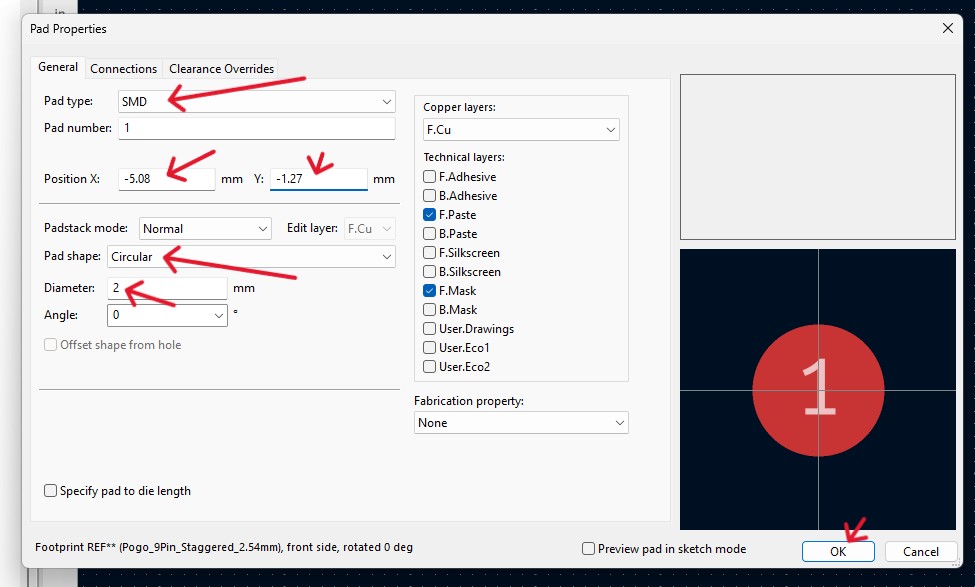
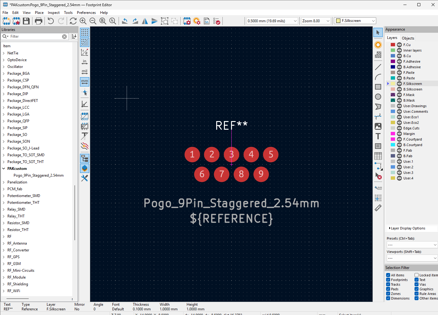
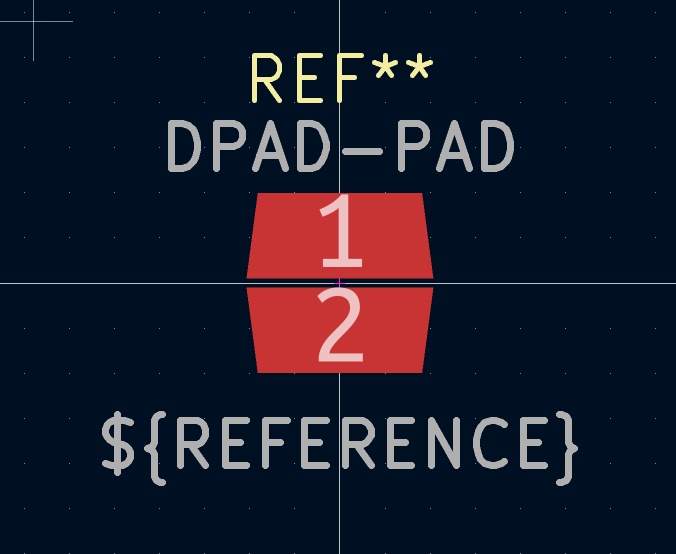
As I've explored in previous weeks, I'm exploring the use of Pogo Pins as the interface for the PAK, which means each cartridge would need a complimentary set of pads to connect with. Using the KiCAD Footprint Editor, I designed a custom 9-pin staggered layout in KiCAD's Footprint Editor.
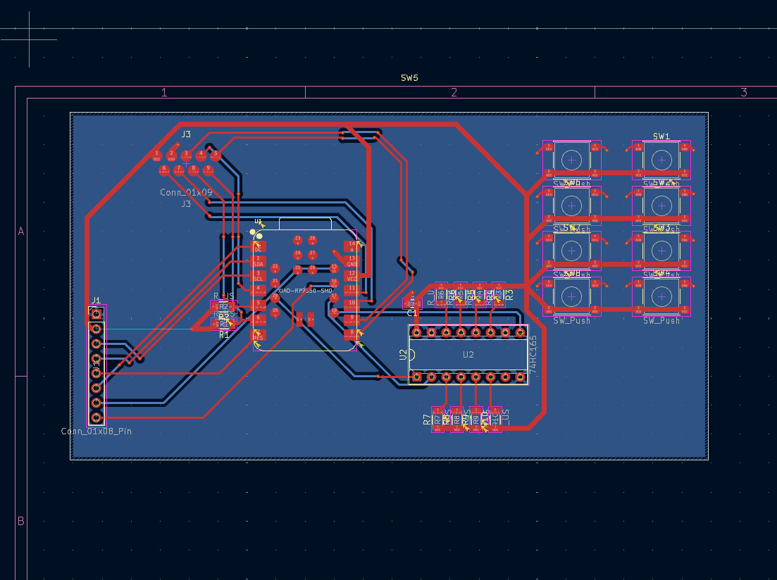
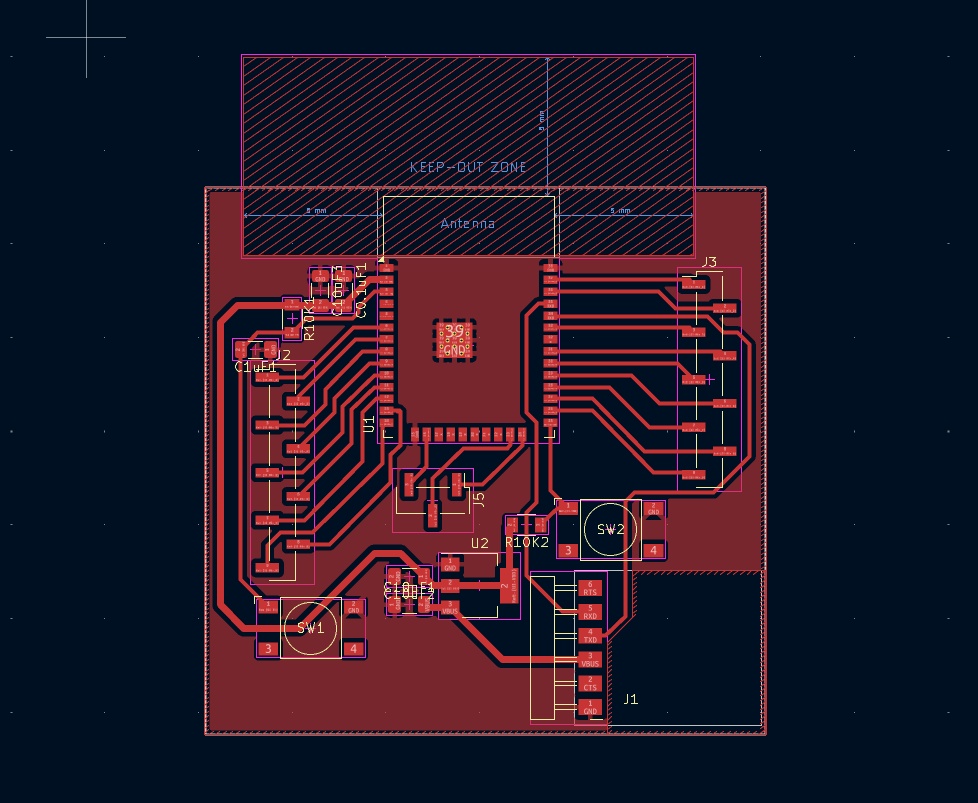
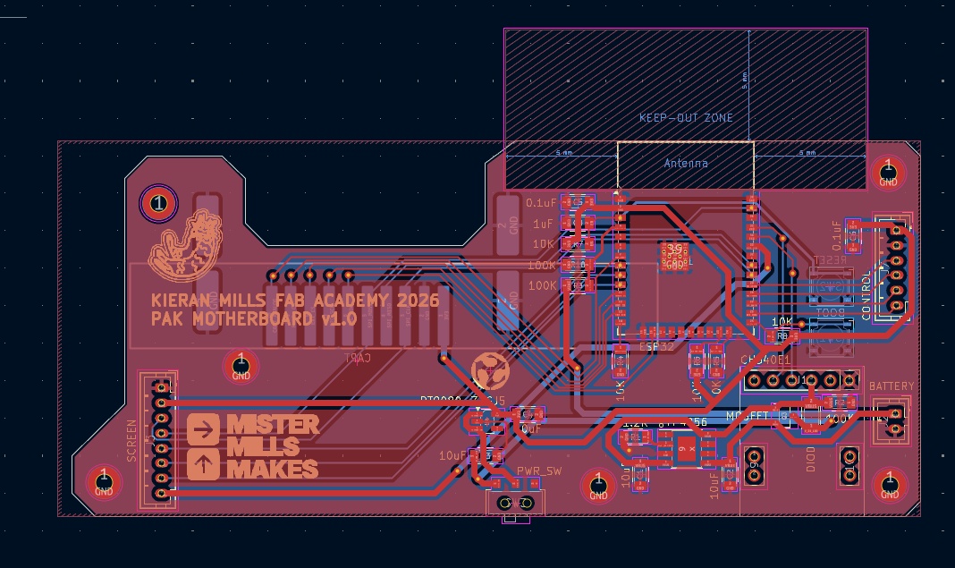
Under the guidance of my mentor, Jorge, I opted to design a two-layer board rather than a simpler single-sided milled board. This was specifically chosen to increase the technical challenge and improve the device's performance. The entire bottom layer is a dedicated GND plane. This provides the shortest possible return path for high-speed signals, significantly reducing the electromagnetic noise generated by the display and flash memory clocks. Implementing this required the use of vias (small holes connecting the front and back layers).
The goal this week was to create a "development board", not something that I can easily slide into the PAK's case right away. Just something that will help me quickly test and prototype the software and electrical connections. The board is using the XIAO, which is technically a daughterboard. I would like to eventually create this board with my own power regulation and and a baremetal RP2350, but I'm going with the XIAO for convenience for now as I continue to learn. The next version will also need precise M2.5 or M3 screw holes for mounting inside the 3D-printed case. The buttons and screen are currently placed for routing ease and debugging, and as
I mentioned in the weekly documentation, D-PADs aren't typically done with push buttons, but this is something to iterate on in the future once we have full access to the PCB milling machine!
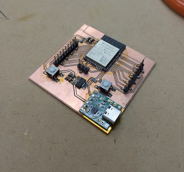
If you read the full article from this week, you'll know that I had a tough ride, but I did manage to prototype and test more aspects of the PAK this week.
My goal for this week was to develop a circuit board for a PAK "dev kit", that is, a less "put together" version of the PAK that I can focus entirely on development with, rather than aesthetics. I wasn't able to mill the board out in a functional state, but I was at least able to test layout and practice my PCB design skills more.
After what I learned this week, I'll be redesigning the dev kit for a single side board, with more surface mounted components wherever possible.
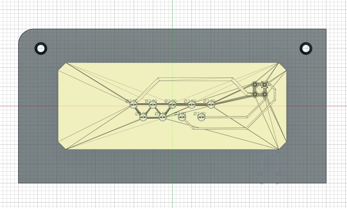
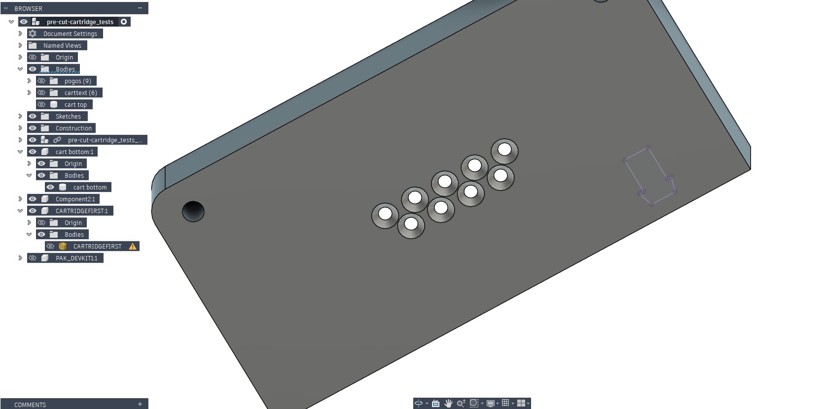
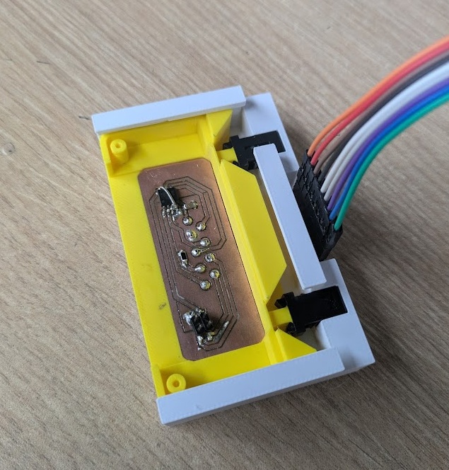
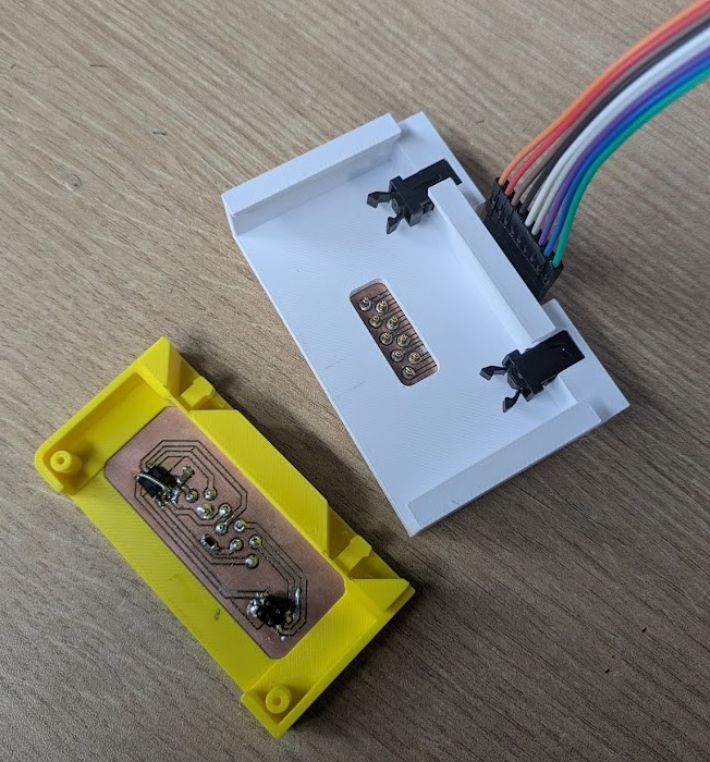
The thing I did get closer to figuring out though was the cartridge mechanism, including the interface for where the pogo pins on the dev kit/main machine will slide into the cartridge.
and coupled with the push push mechanisms that my wife brought with her last week when she came to visit me, I was able to get the first functional prototype of the cartridge interface, with this SUPER satisfying click!
I really wanted this week to be the turning point for the PAK, where I start developing my Fab Academy assignments in the actual PAK architecture. The goal for the start of this week was to create a working prototype of the cartridge and slot mechanism, and then just run all of the Input Devices (and similarly: next week's output devices) through some breakout pins that I could clean up later.
That was the plan of course.
As you can read in this week's assignment page, I managed to get a working prototype but it only cost me my sanity and a little bit of burnout.
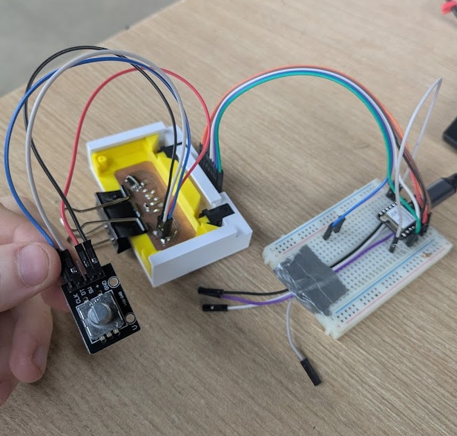
The pogo pins are a neat thing to incorporate. My original plan was to have them run parallel to the push-push latches, but they simply do not have enough spring distance to match the latch spring. It would have also been harder to create two PCBs that would have run perpendicular to the main components inside of both the main device and the cartridge. So I tried running the pins perpendicular to the direction the cart would travel. My thinking was that the pogo pins would be supported by a 3D printed bracket, and I would position them at the right height to juuuuust miss rubbing against the plastic and introducing the lateral motion that would sheer any soldering job. I managed to get it working in principle, but it was delicate. It was not the kind of sturdy I would want for a final polished project.
So I'm making the decision here to abandon the pogo pins and switch to a more typical edge connector solution. I still really want to use the push-push mechanisms because the click is super satisfying, so I'll need to figure out a way to reduce the friction on the receiving end while still having enough tension to make contact with the cartridge pin pads.
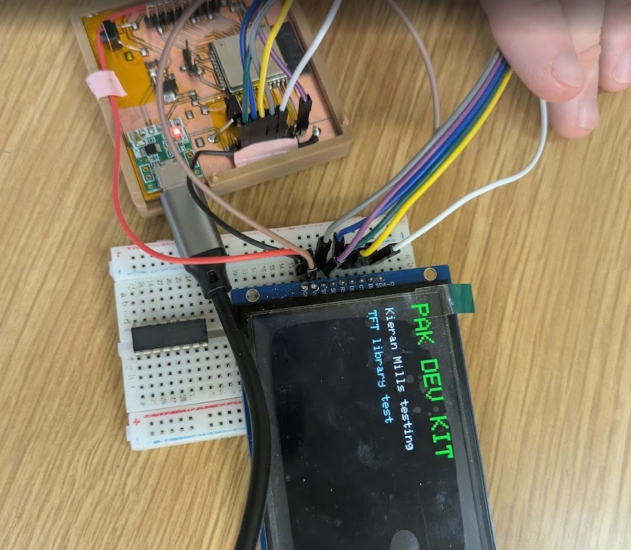
The PAK has two main output devices that are built into the main unit: the 3.5" TFT display and an RGB indicator LED that communicates the current state of the device to the user. My goal for this week was to try integrating more of the output device-based cartridges I had in mind for the final device directly into the cartridge prototype, but if you've read the progress I made in Week 9 (just above) on this, you'll know that I had a lot of trouble getting the cartridge PCB to play nice with the Pogo pins and I spent the next few weeks researching and determining an alternative plan for the pins. That left prototyping to be relatively simple for this week, and was really just an excuse to get the 3.5" screen up breathing for the first time. You can read about all of the bits and pieces on the page for Week 10.
TFT SCREEN
I managed to get the screen powered on through SPI and ran some stress tests to see what data load it could handle.
INDICATOR LEDs
You can again, read more about the process of creating the light pipe tests on the assignment page for this week. The idea of the light pipe is to funnel the light out to the edge of the case and diffuse it so it appears more attractive and easier on the eyes!
DEV KIT
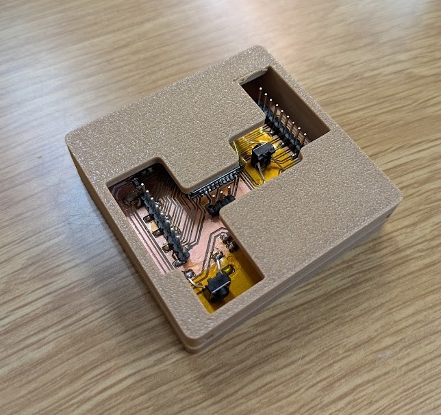
The PAK has taken shape into its second prototype form as of May 5th 2026, with all bells and whistles in tact. I've taken all of the components from the first prototype and printed plastic casings for them. It's not pretty, but almost everything that will be in the final build is there on a fundamental level, and most importantly it works. My next steps are looking ahead at spiral 3. You can read about my continued plans in my midterm review page.
Documentation for the final project across weeks 11 through 14 are a bit cloudy and kind of merge together in places due to my move from Peru to Yokohama. Over these weeks I was ready to fully commit to a new development plan and create the DEV kit again from scratch, and I was successful in creating the very first prototype shown above!
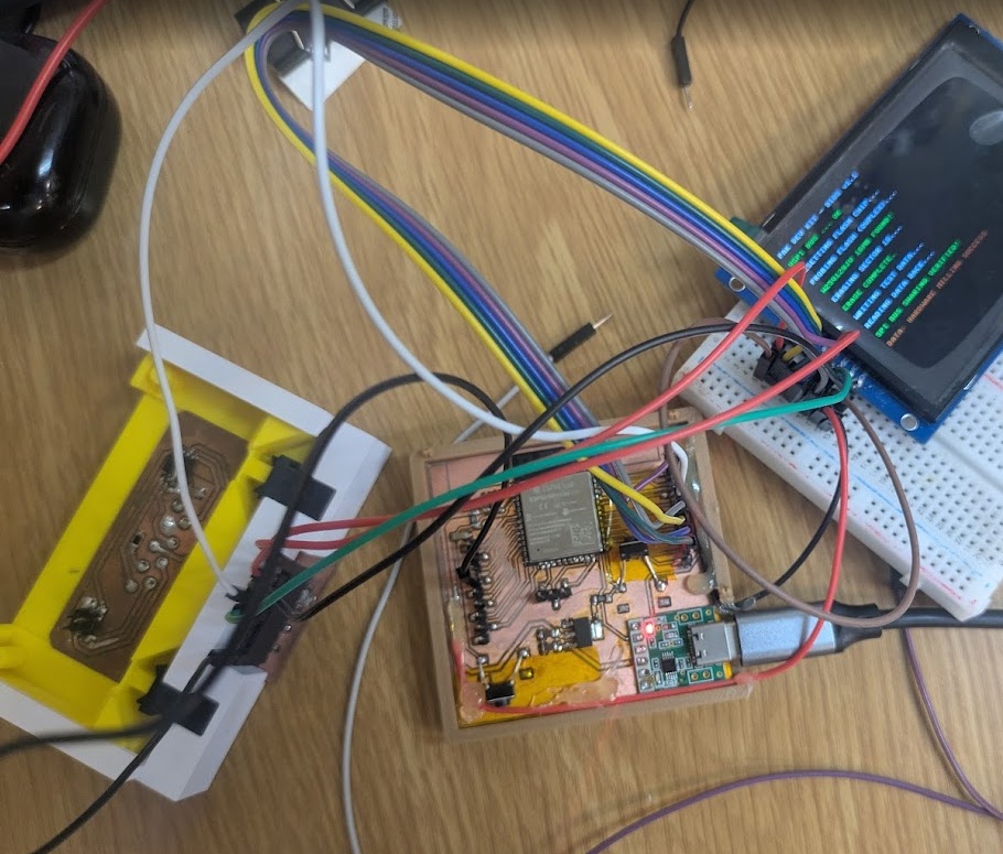
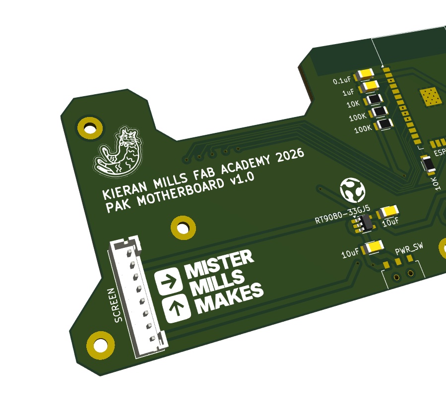
The first step to getting the DEV KIT assembled was getting the motherboard, where all of the other companion boards and components would link up to, designed and milled. So I used what I learned from my existing schematics and pieced together a MUCH better wiring.
Breaking up the DEV KIT into several boards means I can test all of the individual components without having to worry about the whole thing breaking. One by one I was able to test:
THE SCREEN
THE FLASH MEMORY CHIP
THE RGB LED
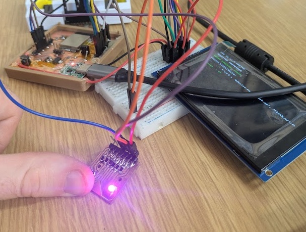
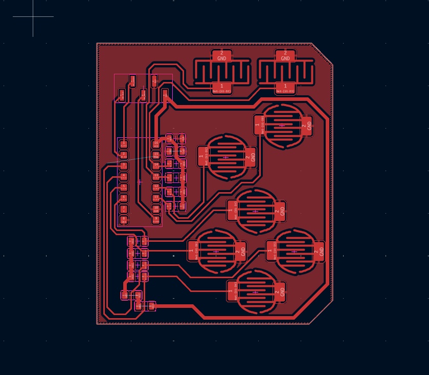
and then I was able to design and mill out a secondary board that would have the shift register and buttons on it. Here you'll see a custom footprint I designed to test out membrane style buttons, which I plan on creating in the molding and casting week.
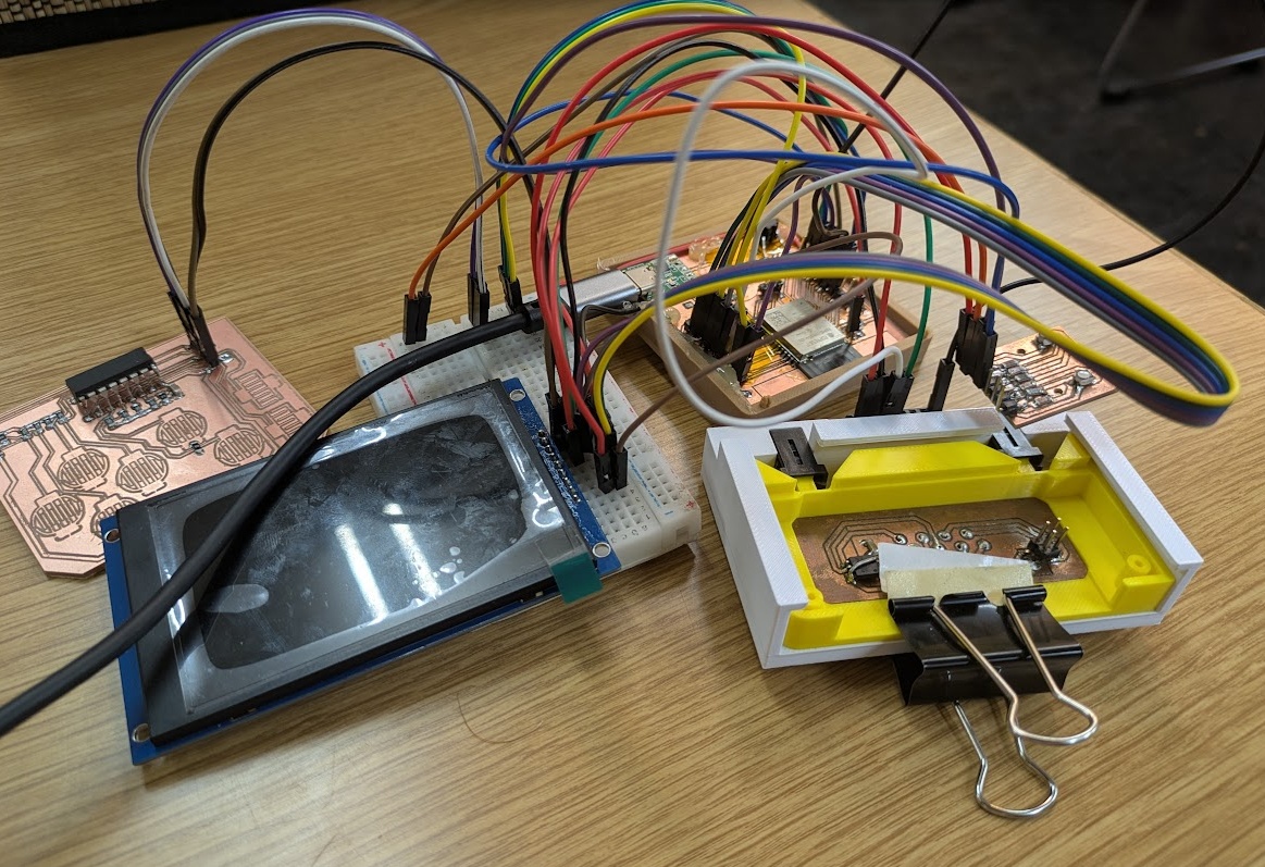
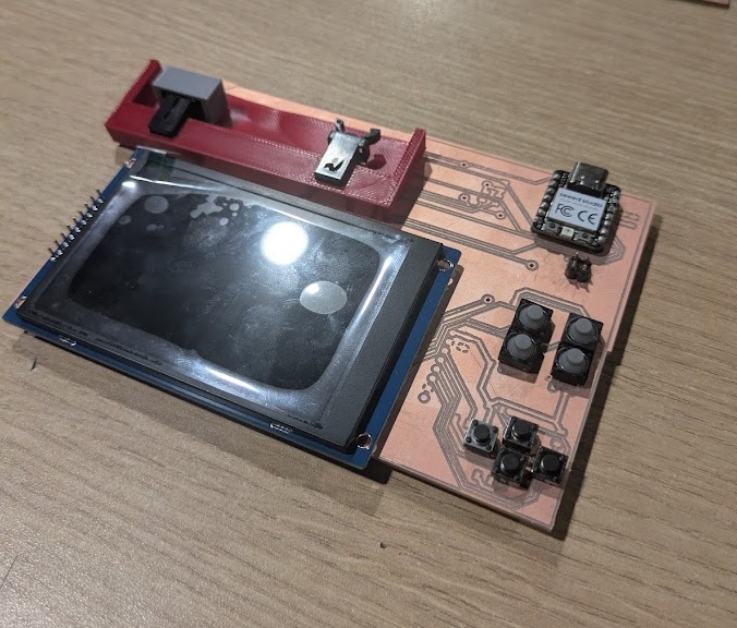
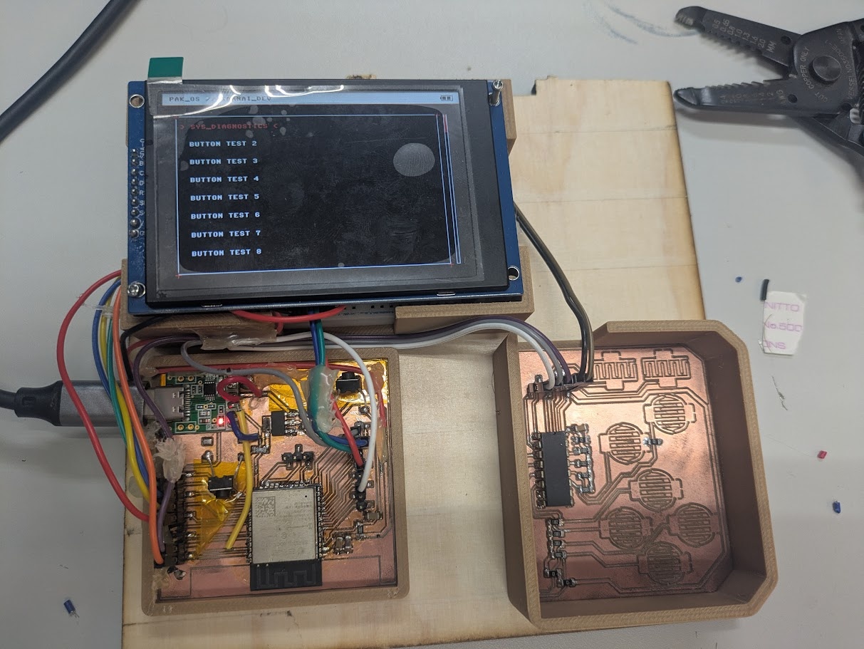
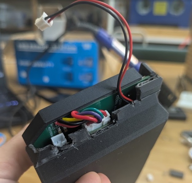
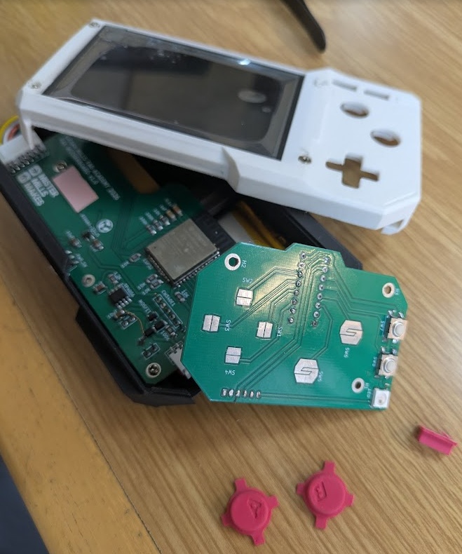
Which brings us to our first fully functional prototype of the PAK. Everything is here! Even if it looks like a bowl of spaghetti, we're officially through our first spiral of development!
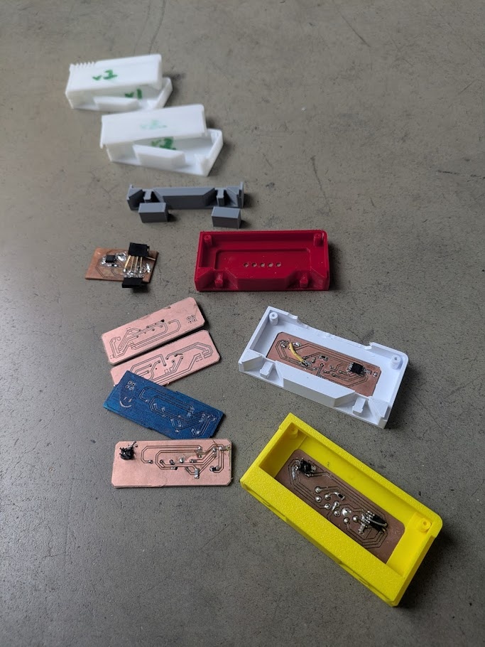
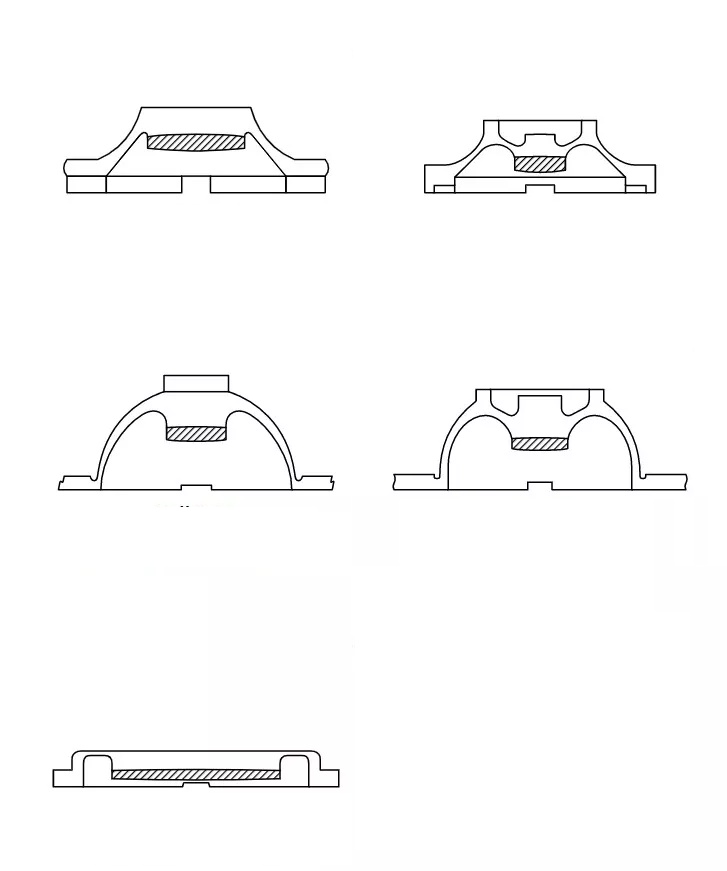
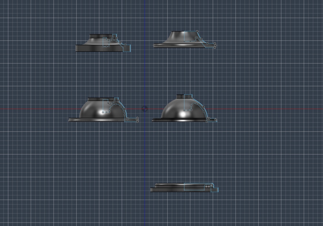
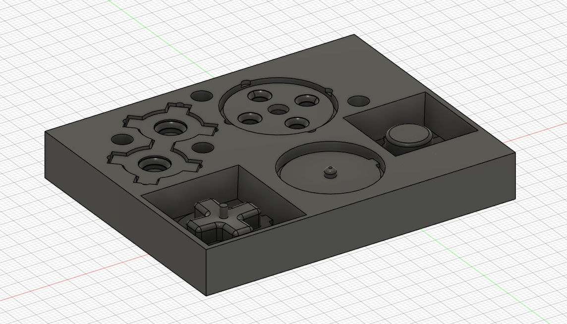
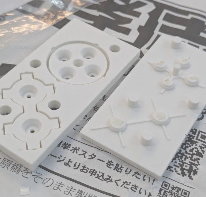
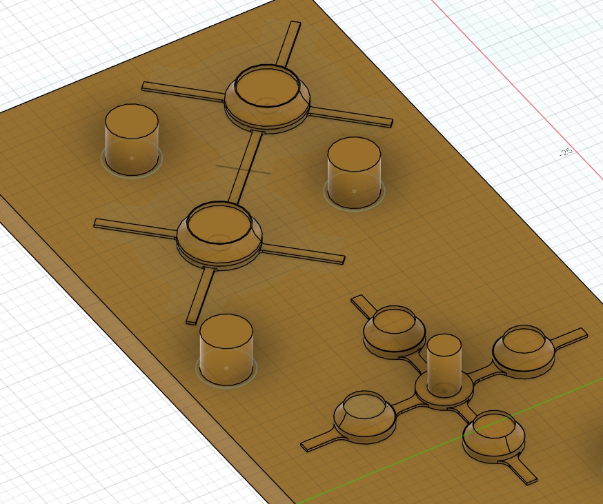
I knew that I wanted a more premium feel for the PAK, and to avoid just simple tactile buttons for the finished product. A lot of consumer electronics that I am modelling the PAK after utilize silicone/rubber membrane pads with conductive carbon pills to bridge the connection between two pads. The silicone/rubber acts like a spring that decompresses the plastic button on top after each press. Normally these molds are made with a specific kind of rubber that best handles the wear and tear and desired feedback, so I knew I would need to iterate and try out lots of different ideas if I wanted to use the silicone product we have in house. I found some great sites with lots of information that lead me to testing a few different kinds of button profiles.
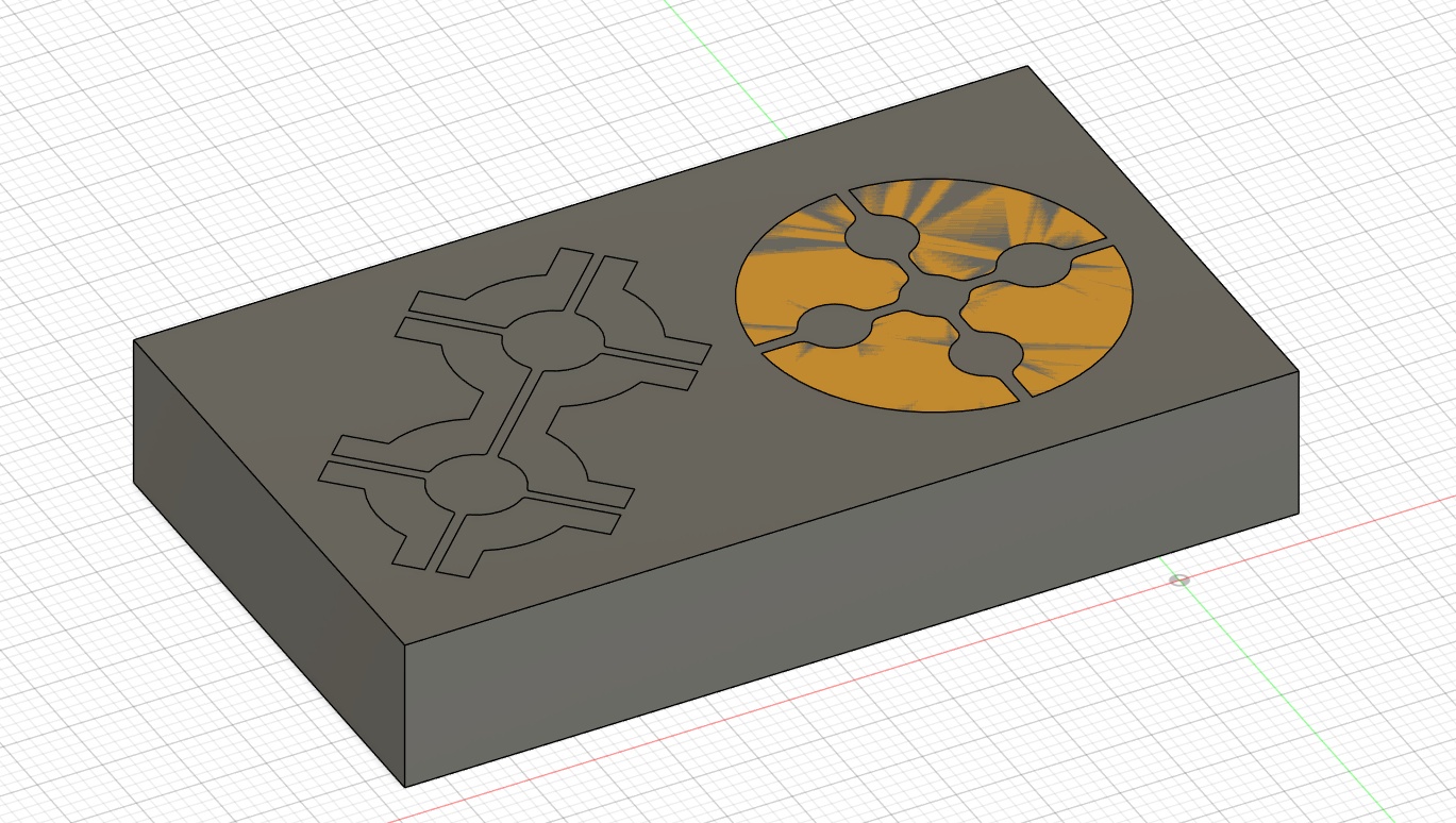
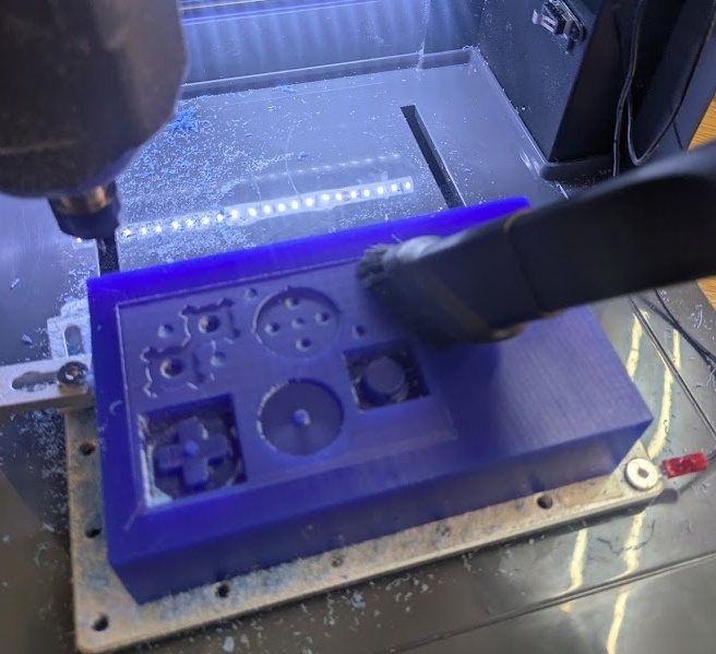
I talk in depth about the process of how to create these buttons over on the assignment page for Week 14 if you'd like to read more about the process. For the next iterations, I actually decided to go with a 3D printed mold (with the lowest possible layer height) as I found the surface finish to be indistinguishable from the milled molds and it was exponentially faster.
The next step was to try out some D-PAD designs, which require a little post/rocker in the middle to prevent multiple directions from being pressed at once.
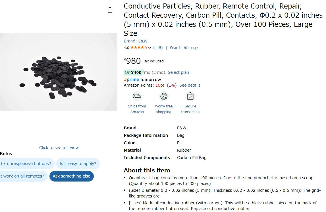
I also found these cheap insertable conductive carbon pills I could add or glue into the moulds.
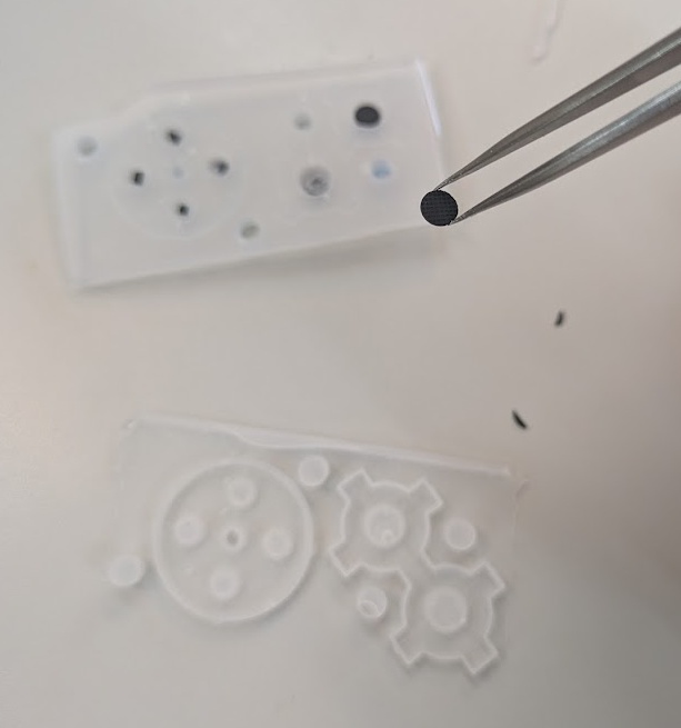
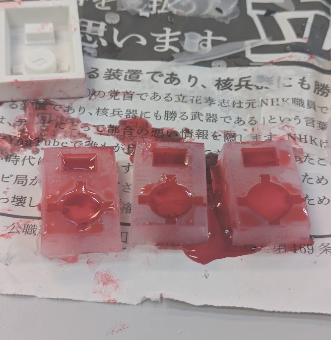
After some initial tests, I was ready to cast the actual silicone rubber. I 3D printed the mold instead of wax milling it because I actually had better success.
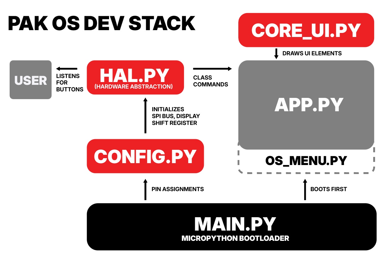
It was time to start developing the foundation to continue building apps/cartridges for the PAK. In Week 15, I dive deep into the choices I made to create the development stack for the PAK, including the many different scripts that are layered and run concurrently on the ESP32. You can read the full dive on the assignment page for this week..
This week, I created two test applications using the above dev stack, the Pomodoro Timer v2 and a Weather Application.
SYSTEM INTEGRATION
With all of the individual components now working in isolation and many working together on the DEV KIT, our next step was going to need to start putting everything in one place.
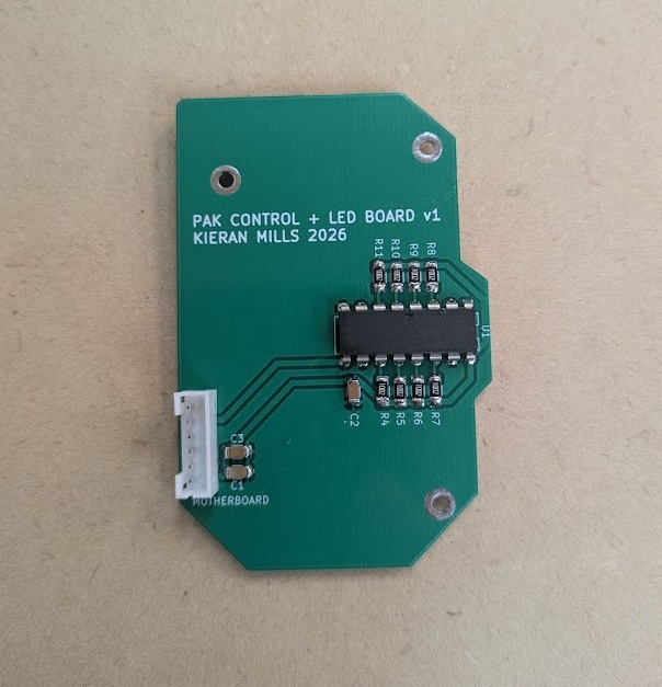
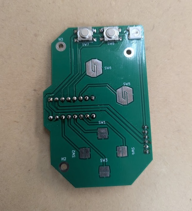
After having the Spiral 2 Dev Kit break on me pretty much immediately after getting into a completed state, I knew it was time to get the final boards (or at least the next iteration) shipped off to a board house so I could stop worrying about being too rough with the system.
and here's what they looked like upon arrival and assembly!
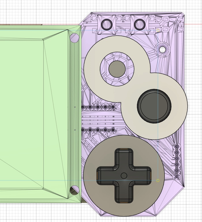
Now that things were starting to come together for the board and I had committed to a placement of the buttons, I figured I would start casting and testing more button designs to get closer to the final iteration. I modelled the D-PAD after a Wii Remote design but altered some of the measurements to have it better fit my board.
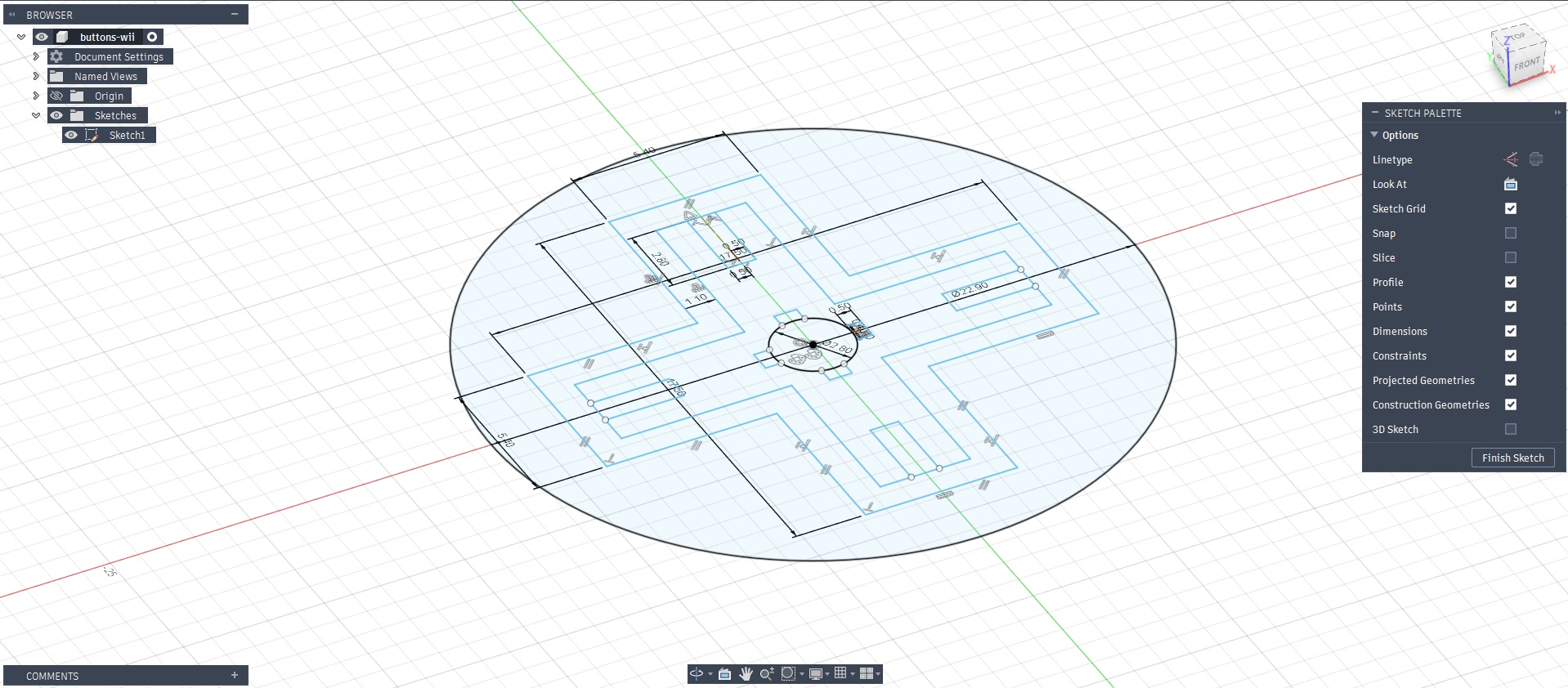
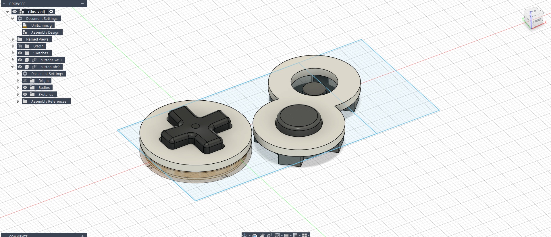
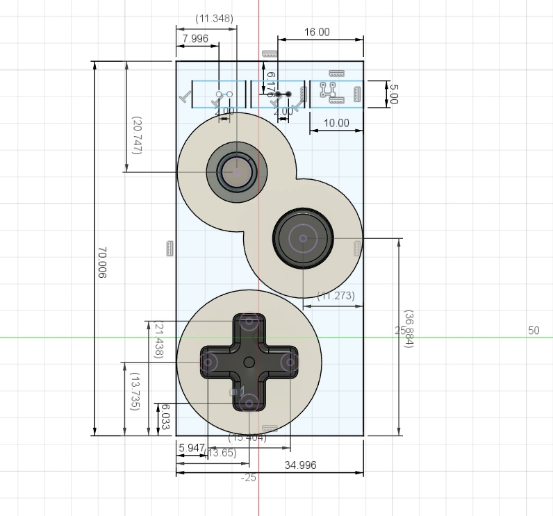
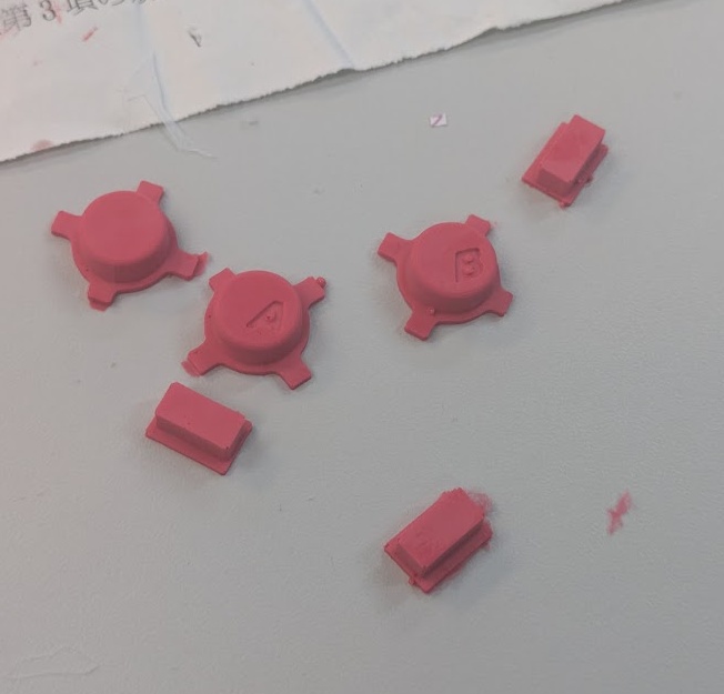
I cast the buttons for the PAK out of plastic using silicone molds which were cast from 3D prints.
The case of the PAK, believe it or not, is actually the lowest prority design item. I made all of my system integration decisions above based on the fact that I can rapid iterate on cases, so if something doesn't fit, I can just move things around in CAD and reprint. The top priority were the PCBs, which take the most time (even if I was doing those 2 in house). My process for developing the case for the PAK is better described in depth on the assignment page for Week 16.
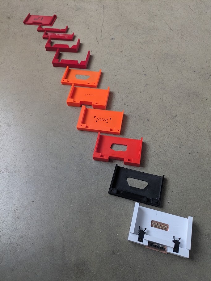
However, I spent a crazy long amount of time iterating on the case design. Printing 5 different prototypes this week, refining the shape and aesthetic (and function - making sure it all fits) each time.
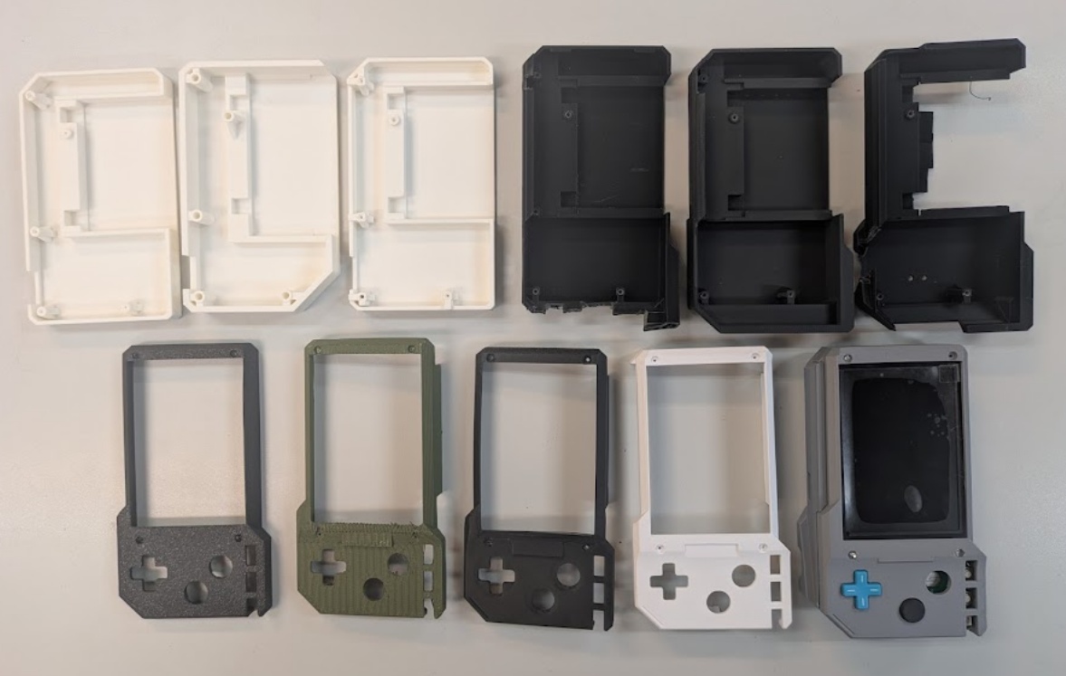
I was mostly concerned with the fit and screw bosses of the PCBs, and then ran into some issues with how my JST connectors were fitting, so I had to revise the edges so I could actually unplug and plug in the the connectors, since I had them pretty flush to the walls.
but then I became totally sucked into how I would actually assemble and disassmble the device. I really wanted to be able to have it come apart really easily so I could show people what was inside, but that's actually a really tough thing to do, especially when you're already deep into other priorities. I ended up going for 3 screw holes on the bottom to seal the whole thing shut and some ribs around the inner edges to help with the gap, something you find in other electronics enclosures.
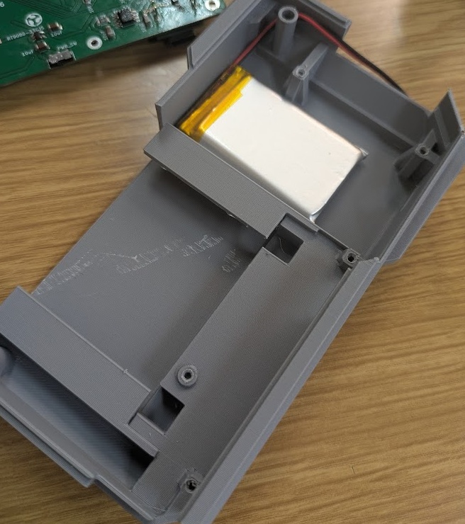
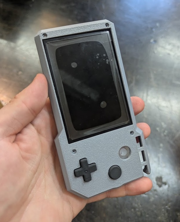
After a full week of just printing prototypes and testing what works and what doesn't, I decided to bite the bullet and call it (I really could work on this alone for weeks to get it just right) and I decided to order some resin prints from JLCPCB (since there is no SLA printer here at Fab Lab Kannai). Here's an image of the FDM printed case that I did in house, and what I'm likely going to be presenting with since the JLCPCB parts might not make it in time!
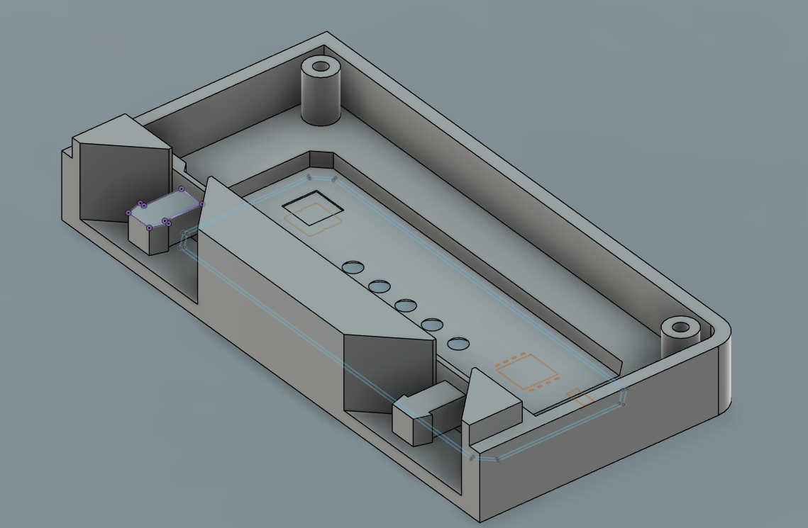
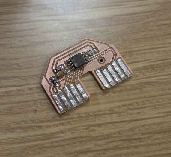
I knew that I would need to redesign the cartridge at some point to fit to the new motherboard and daughterboard combo, so I took the opportunity to see if I could come out of this with a slightly smaller footprint - something that would afford me better system integration.
I knew that my pogo pin design from earlier just wasn't going to cut it. The latch mechanism was just too large to accomodate pins in the same direction, and I wouldn't be able to run pins perpendicular to the board since there would be a lot of shear force from insertion. I thought for a while, and considered doing an edge connector board, but I would lose the amazing click mechanism that I spent so much time researching and planning for, so I kept looking. I found these excellent sized spring loaded connectors on DigiKey that I thought would be a good substitute.
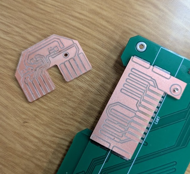
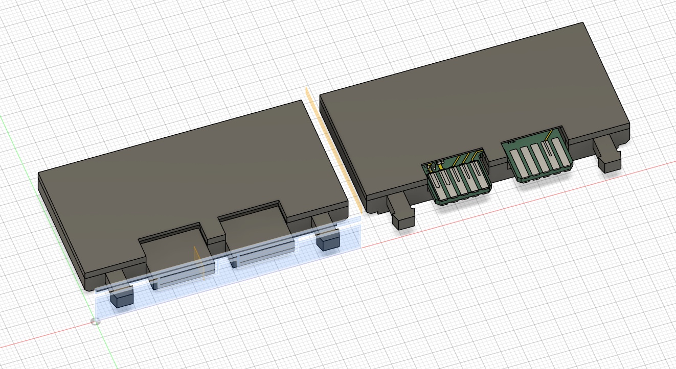
I designed a new footprint for the PCB in KiCAD. I made it shaped a bit like an "A" to help with the force of inserting and removing the cartridge. The gap in between the pins would have a plastic shelf that could help with a bit of that force.
However, at this point, I hadn't actually got the final PCBs in my hands, so I was really concerned with alignment. While I was designing the final motherboard, I added extra long solder pads for where I could attach an extension daughter board, which you can see in the image above, in case my springs didn't line up nicely with the cartridge (and so I could correct an error I made - swapping MISO and MOSI by accident). In hindsight, this was a really stupid decision as it just made things difficult to design around, rather than just coming up with a design and tolerance for error in the beginning - but hey, I learned a great lesson here and it's not one I'd be happy to repeat!
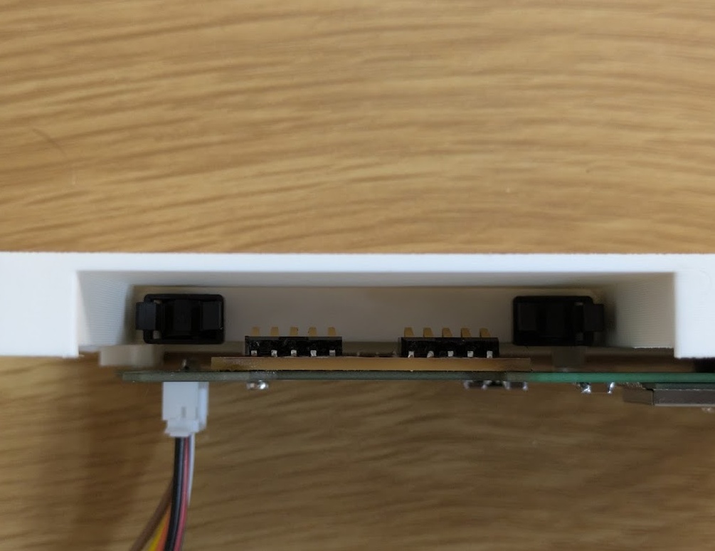
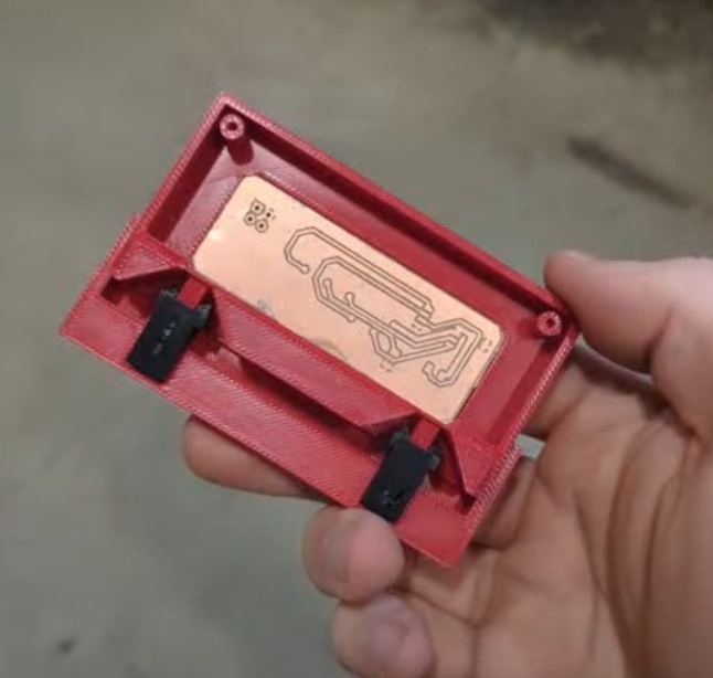
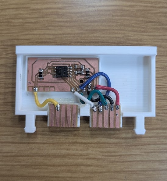
Once the parts arrived, I was able to solder them on, but I had a new problem. Getting the exact height for the circuit board to sit to make the right amount of contact with the spring loaded pins! I thought I had calculated this properly Fusion, my initial tests were either too loose and not making enough contact or too tight and I risked ripping the spring pins right off the board.
I unfortunately was limited by the height of cartridge's soldered components in the end. If I was just a millimeter closer to the board, I would have had to settle for this ugly bodge, but you live and learn.
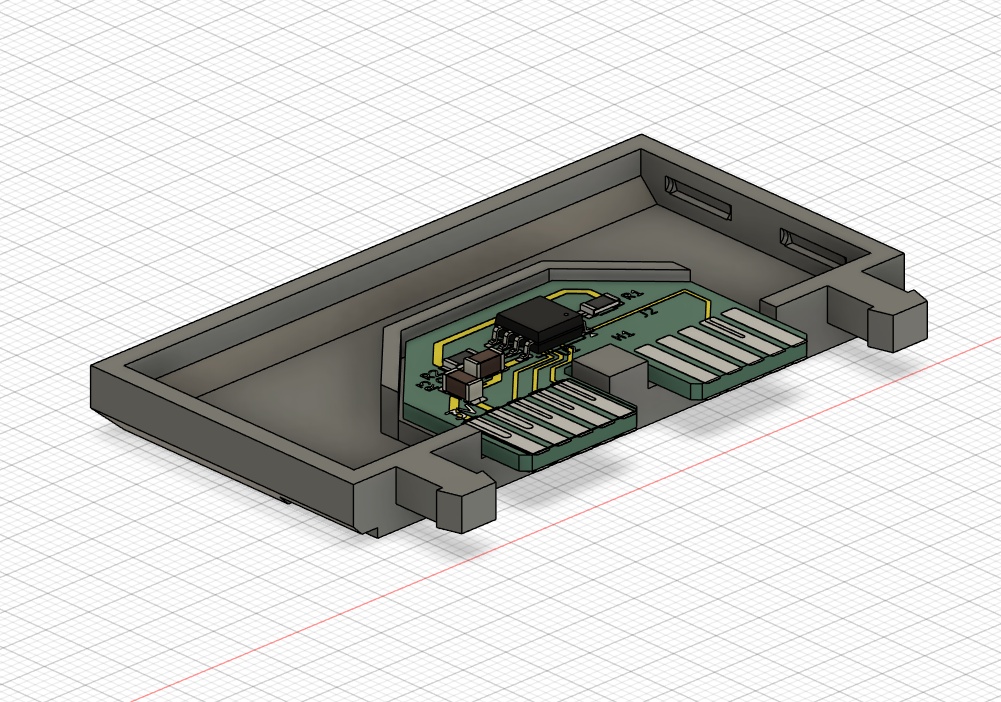
The fix is: three seperate "boards", two of them at the height where the pins would interface naturally, and the main board with all of the components isolated and positioned off to the side, and then connected with soldered wires. It's certainly not graceful, but I was anxious about getting the rest of the work done. Without redesigning the rest of the main unit, the next logical fix would be using a double-sided board and just having the cartridge mount upside down with the components facing the other way and the pins interfacing on the other side. I tried to give this ago, but then I was reminded about just how difficult it was to do.
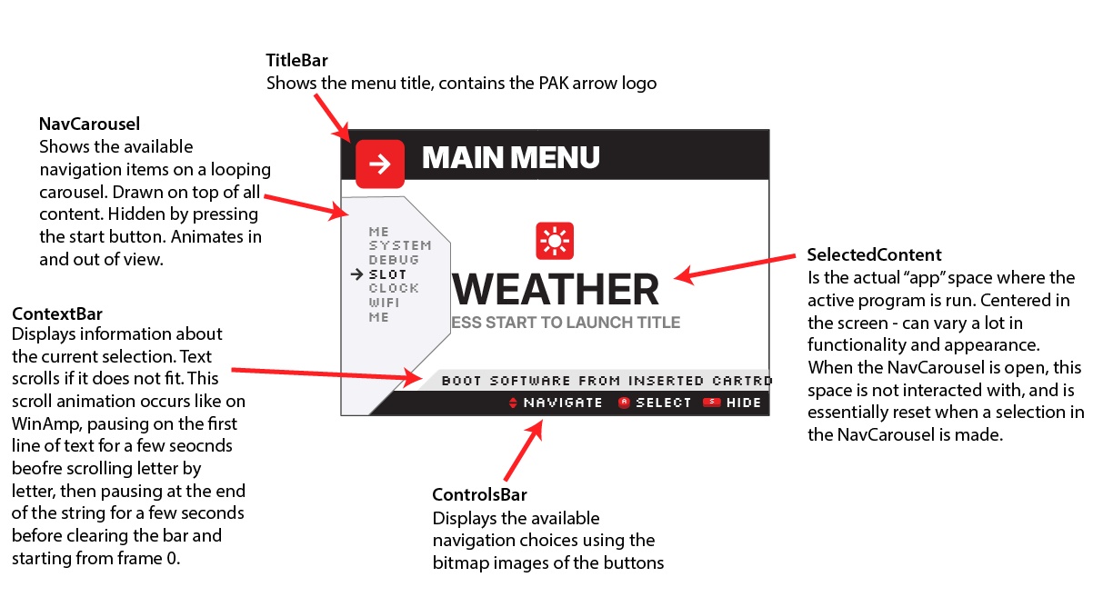
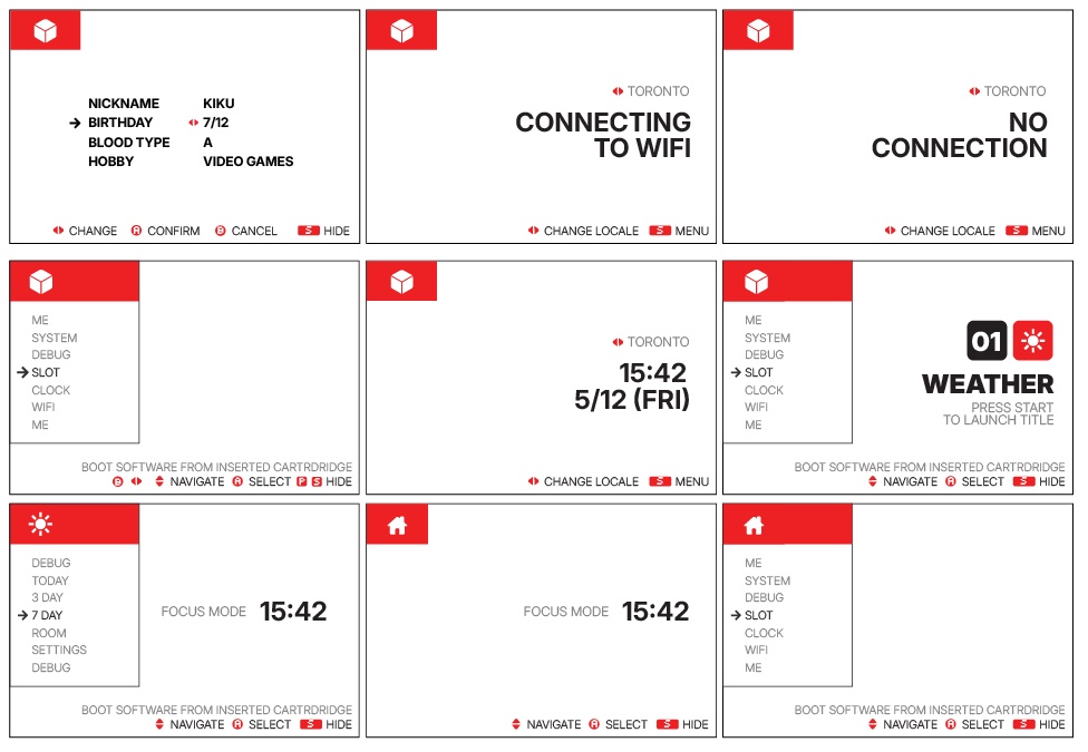
I spent the first half of my last week before my presentation nailing down the user interface and reconfiguring the ui_core.py that I explain earlier in spiral 2. Since I was running low on time, and I had already coded a lot of what I needed to do myself, my workflow for this involved drafting out designs in Illustrator and then asking Gemini to take my graphics and apply them to my existing code base, updating the classes I defined earlier with the new looks. The behaviours all pretty much stayed the same.
I would ultimately need to scale things down, even with the minimal approach to the UI above, as the SPI TFT display coupled with the ESP32 really couldn't handle a lot of the really fluid user experience I was aiming for. I bought these screens all the way back in week 4, and I didn't know enough back then to realize how difficult and slow they would be to work with without adequate memory on board. I found some bodges though and I got it working.
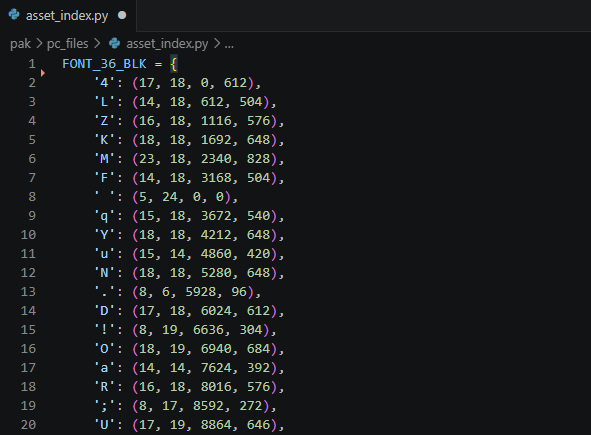
The big tricks were creating bitmap versions of the fonts I wanted to use and saving them in an assets.bin file on the device. I asked Gemini to create me a script that could take a .ttf file and output a literal pixel-by-pixel array of what each letter looked like. The downside is that you lose any anti-aliasing in this approach, so I made sure to find fonts that looked good at the sizes I needed them at. The original .bin file I configured was actually way too big to load into memory all at once, so I had to create a second asset_index.py script that my applications could consult to find the byte offset to use to pull out the correct character.
The full code base, that builds off of my work from the section above (week 15), can be accessed here:
Before I could get any of the apps actually running off cartridges, I would need a way to actually initalize the cartridge as a file system, which thankfully, already exists. This handy script from Peter Hinch allows me to create a littlefs filesystem on the W25Q128JVSIQ flash memory chips on each cartridge, and then essentially just read from them as though they were part of the ESP32/micropython's own file system. The first app I would actually need to code would be a cartridge manager that could format and push the scripts to the device.
Using the FLASH method from flash_spi, I was able to create a script that was able to do just that! I used a lot of the same code I had already tested back in week 08 ran into a lot of the same errors as I did back in week 08 and week 09 as well, but with a bit of debugging support from Gemini, I was able to get an app that I could launch from os_menu.py and push other scripts to the cartridge's flash memory.
APP_DESC = "Cartridge Data Manager"

import os
import time
import sys
import machine
from flash_spi import FLASH
from hal import hw, QuitToMenuException
import ui_core
import config

class CartManagerApp:
    def __init__(self):
        self.current_sel = 0
        self.carousel = ui_core.NavCarousel(
            0, 54, 240,
            ui_core.sys_font_16_act,
            ui_core.sys_font_16_gry,
            ui_core.sys_spr_arrow,
            ui_core.sys_spr_app_icon
        )
        self.refresh_menu()

    def refresh_menu(self):
        self.staging_apps = self._get_local_apps()

        self.menu_items = []
        self.file_map = {}
        self.descriptions = []

        for app in self.staging_apps:
            if app == "NO LOCAL APPS":
                self.menu_items.append("NO LOCAL APPS")
                self.descriptions.append("NO VALID APPS IN /APPLOAD")
                continue

            display_name = app[:-3].upper() if app.endswith('.py') else app.upper()

            self.menu_items.append(display_name)
            self.file_map[display_name] = app
            self.descriptions.append(f"PUSH {display_name} TO /CART")

        self.menu_items.extend(["FORMAT CART", "RETURN"])
        self.descriptions.append("ERASE AND FORMAT CARTRIDGE AS LITTLEFS")
        self.descriptions.append("RETURN TO OS MENU")

        #cursor fix
        if self.current_sel >= len(self.menu_items):
            self.current_sel = max(0, len(self.menu_items) - 1)

    def _get_local_apps(self):
        apps = []
        path = '/appload' if sys.implementation.name == 'micropython' else 'appload'
        try:
            for file in os.listdir(path):
                if file.endswith('.py') and file not in ['__init__.py', 'main.py']:
                    apps.append(file)
        except OSError:
            pass
        return apps if apps else ["NO LOCAL APPS"]

    def copy_file(self, display_name):
        actual_filename = self.file_map.get(display_name, display_name)
        src = f"/appload/{actual_filename}"
        dest = f"/cart/{actual_filename}"

        ui_core.sys_context.draw(f"COPYING {display_name}...")

        try:
            if os.statvfs('/') == os.statvfs('/cart'):
                raise Exception("NO CART DETECTED")

            src_size = os.stat(src)[6]

            with open(src, 'rb') as f_src:
                with open(dest, 'wb') as f_dest:
                    while True:
                        chunk = f_src.read(512)
                        if not chunk:
                            break
                        f_dest.write(chunk)

            try:
                dest_size = os.stat(dest)[6]
                if src_size != dest_size:
                    raise Exception("VERIFY FAILED")
            except OSError:
                raise Exception("WRITE FAILED")

            ui_core.sys_context.draw("TRANSFER COMPLETE")

        except Exception as e:
            err_msg = str(e)[:15].upper()
            ui_core.sys_context.draw(f"ERROR: {err_msg}")

    def get_controls(self):
        if self.carousel.is_open:
            sel = self.menu_items[self.current_sel]
            #dont delete these buttons haha
            if sel not in ["FORMAT CART", "RETURN", "NO LOCAL APPS"]:
                return {"UD": "NAVIGATE", "A": "EXECUTE", "B": "DELETE", "START": "HIDE"}
            return {"UD": "NAVIGATE", "A": "EXECUTE", "START": "HIDE"}
        else:
            return {"START": "MENU"}

    def run(self):
        hw.display.fill(hw.c_wht)

        self.carousel.draw_header()
        self.carousel.draw(self.menu_items, self.current_sel)

        ui_core.sys_controls.draw(self.get_controls())
        ui_core.sys_context.draw(self.descriptions[self.current_sel])

        prev_btn = 0

        while True:
            btn = hw.read_buttons()
            pressed = btn & ~prev_btn
            prev_btn = btn

            if pressed:
                if pressed & config.BTN_START:
                    self.carousel.toggle(self.menu_items, self.current_sel, hw.c_wht)
                    ui_core.sys_controls.draw(self.get_controls())
                    ui_core.sys_context.draw(self.descriptions[self.current_sel] if self.carousel.is_open else "")

                elif self.carousel.is_open:
                    if pressed & config.BTN_DOWN:
                        self.current_sel = (self.current_sel + 1) % len(self.menu_items)
                        self.carousel.draw(self.menu_items, self.current_sel)
                        ui_core.sys_controls.draw(self.get_controls())
                        ui_core.sys_context.draw(self.descriptions[self.current_sel])

                    elif pressed & config.BTN_UP:
                        self.current_sel = (self.current_sel - 1 + len(self.menu_items)) % len(self.menu_items)
                        self.carousel.draw(self.menu_items, self.current_sel)
                        ui_core.sys_controls.draw(self.get_controls())
                        ui_core.sys_context.draw(self.descriptions[self.current_sel])

                    elif pressed & config.BTN_B:
                        sel = self.menu_items[self.current_sel]
                        if sel not in ["FORMAT CART", "RETURN", "NO LOCAL APPS"]:
                            actual_filename = self.file_map.get(sel, sel)
                            try:
                                os.remove(f"/appload/{actual_filename}")
                                ui_core.sys_context.draw(f"DELETED {sel}")
                                time.sleep(0.5)

                                self.refresh_menu()

                                hw.display.fill(hw.c_wht)
                                self.carousel.draw_header()
                                self.carousel.draw(self.menu_items, self.current_sel)
                                ui_core.sys_controls.draw(self.get_controls())
                                ui_core.sys_context.draw(self.descriptions[self.current_sel])
                            except OSError:
                                ui_core.sys_context.draw("ERROR: CANNOT DELETE")

                    elif pressed & config.BTN_A:
                        sel = self.menu_items[self.current_sel]

                        if sel == "RETURN":
                            raise QuitToMenuException()

                        elif sel == "FORMAT CART":
                            ui_core.sys_context.draw("FORMATTING... PLEASE WAIT")
                            try:
                                try:
                                    os.umount('/cart')
                                except OSError:
                                    pass

                                tft_cs = machine.Pin(config.PIN_TFT_CS, machine.Pin.OUT)
                                tft_cs.value(1)

                                hw.spi.init(baudrate=5_000_000)

                                cs = machine.Pin(config.PIN_FLASH_CS, machine.Pin.OUT)
                                cs.value(1)
                                time.sleep_ms(1)

                                cs.value(0)
                                hw.spi.write(bytearray([0xFF]))
                                cs.value(1)
                                time.sleep_ms(10)

                                cs.value(0)
                                hw.spi.write(bytearray([0x66]))
                                cs.value(1)
                                time.sleep_ms(1)

                                cs.value(0)
                                hw.spi.write(bytearray([0x99]))
                                cs.value(1)
                                time.sleep_ms(30)

                                flash_dev = FLASH(hw.spi, (cs,))
                                os.VfsLfs2.mkfs(flash_dev)
                                os.mount(flash_dev, '/cart')
                                ui_core.sys_context.draw("FORMAT COMPLETE")

                            except Exception as e:
                                err_msg = str(e)[:15].upper()
                                ui_core.sys_context.draw(f"FMT ERROR: {err_msg}")

                            finally:
                                hw.spi.init(baudrate=40_000_000)

                        elif sel != "NO LOCAL APPS":
                            self.copy_file(sel)

            time.sleep(0.01)

def main():
    app = CartManagerApp()
    app.run()
The next step would be to start porting over some of the scripts I had already written in previous weeks on other hardware (sometimes simulated) onto the current iteration of the PAK with all the updated pinouts and hardware changes. The first app I coded all the way back in Week 04, the pomodoro timer, was the first cartridge I had in mind. Since I had all of the basics of my operating system and UI elements in simple classes, really all I had to do was bring over the logic of the timer and countdown and make it function on the larger display - which was farily simple to do. I asked Gemini with some help on fixing the screen tearing issues, as I've mentioned - the SPI screen really isn't as fast as I thought it was going to be originally, so I need to allocate some memory to a frame buffer for elements that are going to change often on screen. Gemini provided me with some code that reserves portions of the memory for the exact size of block to be drawn and then does some garbage cleanup with gc.collect() when we transition to different states that won't reuse assets.
Developing applications for the PAK is relatively straightforward. The software stack, described earlier, essentially just looks for python scripts in a few different directories (including the file system stored on the cartridge) and then populates a list on the home menu. My next demo app, since at the time I was having some trouble, would be a simple input tester - showing button presses on screen. This one was super straightforward to put together.
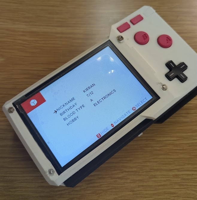
After that, I added a little "my profile" page reminiscent of early PDAs and gaming devices. Needed a bit of charm. These values are read and saved to a .json file stored locally on the ESP so in theory, other applications could be set up to read from them!
Next up I worked on a Date/Time app that could show the time in the three locales I've been studying in the last 5 months. The ESP32 does have an onboard clock but it loses persistance without power, so I would need to take advantage of my specific ESP32's onboard WiFi antenna to poll internet time. I added the SSID and security info of my router to the root of the ESP's filesystem in a .json folder and then a python script could poll for internet time and display it in EST/EDT, PET and JST! I did the same with the weather application I wanted to create, that could use an onboard DHT11 sensor to read the ambient temperature in the room as well as show you the forecast!
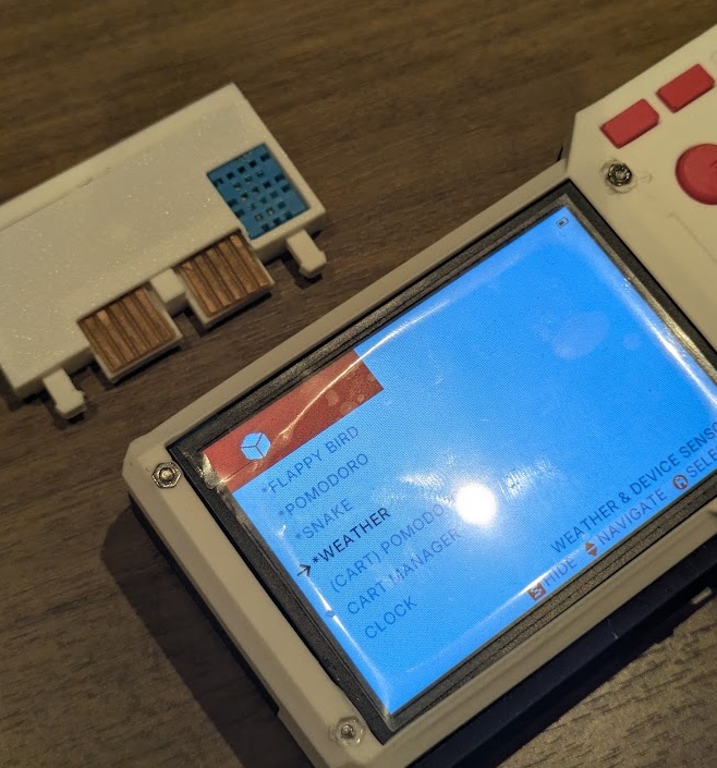
With my code base now easy to iterate on, I uploaded my entire code base to Gemini and asked it to help code some simple games to serve as proof of concepts for the PAK. I think the lowest hanging fruit for a simple device (that I've been struggling with memory and screen buffering on) was Flappy Bird, Doodle Jump and Snake, all shown below.
At this point, I only really had 3 physical cartridges fabricated, but it was possible to load multiple scripts on to a single cart (they are 16MB after all)... but I figured that would kind of defeat the purpose of the device haha! All of the scripts for the apps I coded (and vibe coded) can be found here:
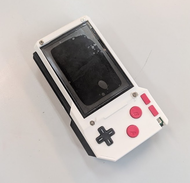
On the Thursday right before my Monday presentation, the polished resin prints from JLCPCB arrived! I was so nervous they were going to arrive late but incredibly relieved that they came early! They looked absolutely incredible, especially the transparent resin case I ordered as a backup. It felt like all the hard work was finally crystalizing into a real, physical product.
The first step was using my soldering iron to carefully press-fit the metal nuts into the top case to hold the screen in place. It's a delicate process where you have to heat the nut just enough so it melts perfectly into the plastic without warping the surrounding area or leaving burn marks.
Getting all of the components into the case and aligned to their stand-offs and screwholes was incredibly satisfying. However, I spent a surprisingly long time just adjusting the screw tightness. If the screws were too tight, the rubber membranes would stay compressed and the buttons would stick. If they were too loose, the controls felt mushy and unresponsive.
With the physical devices finally assembled, I spent the next two entire days locked in the photobooth. I needed to collect a mountain of pictures and videos for my final presentation. I took video demonstrations, hero shots, and some stop-motion animations. Finally, I took all of that footage, along with my exploded render view from Fusion, and edited my final project slide in Illustrator and my presentation video in CapCut. You can find a link to the finished thing at the top of this page!
With 1-2 days left before my presentation, I really wanted something fun to end on. You know the meme: "Can it run DOOM?" I decided to lean into it and see if I could actually get DOOM installed on the PAK.
Since I was already using MicroPython on my main ESP32, getting a native C application like DOOM running would mean destroying my partition and reformatting all of my hard work, ultimately losing the functionality of what I built in the first place, so my compromise here is that Doom isn't actually going to run on a cartridge, it pretty much needs to occupy the full 4MiB of flash storage on the chip to make this work. I transferred all of my working PAK components and software over to the new clear model so I could get Doom running exlcusively on the white model.
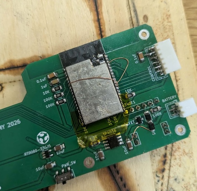
For the original case, I ended up soldering a new ESP32-WROVER to a spare motherboard. I realized pretty quickly that the WROOM chip I was using just would not be able to hold the game in the flash memory and run it on it's own memory. I needed more firepower so I ordered a devboard on Amazon that came the next morning. The WROVER is slightly longer than the ESP-WROOM-32 I designed the board for, but thankfully, the pinout for the overlapping footprint is practically identical. I just put some Kapton tape down over the extra pins to prevent any shorts and managed to get it in!
To actually get the game running, I started with an old 2017 repo (espressif/esp32-doom). Because of how old the codebase was, I had massive issues compiling it. I knew I would need to completely swap out the screen logic and button logic to make it work with my ST7796 TFT and the 74HC165 shift register, but most of the problems I encountered were way above my expertise. I had Gemini help me rewrite the C code to match my specific hardware, and we came across some major hurdles along the way:
The modern framework deprecated and moved almost all core APIs that the 2017 Doom port relied on. We had to manually re-link drivers for SPI, Partitioning, GPIO, and Flash, and update dozens of header paths (e.g., swapping esp_spi_flash.h for spi_flash_mmap.h). The compiler encountered code written in older C standards that were no longer valid. We had to fix "multiple definition" errors where the 2017 port used custom functions (like access) that conflicted with the modern ESP-IDF Virtual File System, and update outdated macro names (e.g., changing portTICK_RATE_MS to portTICK_PERIOD_MS).
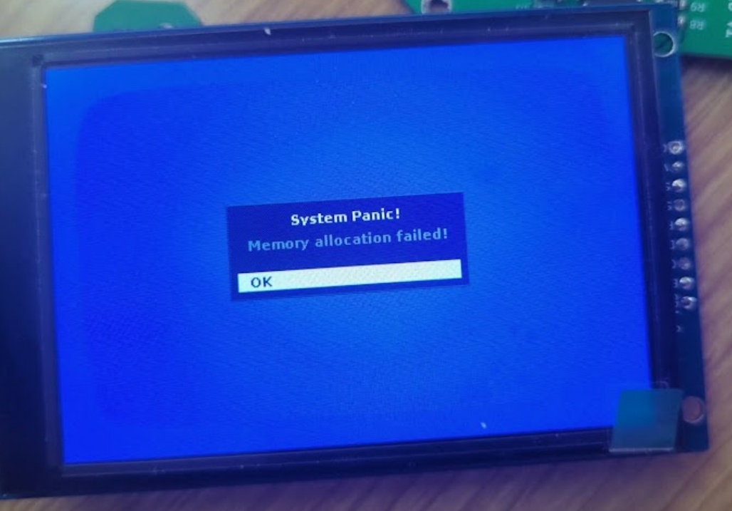
This was the most critical issue. The original code attempted to allocate massive video buffers in the ESP32's tiny internal memory, which immediately triggered memory allocation panics. We fixed this by forcing the engine to allocate the frame buffer in the 8MB PSRAM and utilizing a permanent, tiny 640-byte internal "bounce buffer" to stream the display.
Because the Doom engine is so demanding, it was essentially "hogging" the CPU and failing to yield to background tasks, triggering the Task Watchdog Timer to reset the board. We resolved this by injecting vTaskDelay hooks to feed the Watchdog without impacting game performance.
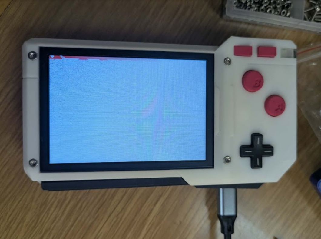
We had to manually perform the hardware-level initialization of the ST7796 panel, resolve the inverted color output (the infamous "cyan tint" issue), and implement a manual coordinate offset to center the 320x240 frame inside the PAK's 480x320 physical screen, all while painting a hardware-level black border. The audio engine was trying to write to an uninitialized memory queue. Since my project didn't require onboard audio, we performed an "audio lobotomy" by stubbing out those functions to ensure they would return "success" to the Doom engine without trying to access hardware memory that didn't exist.
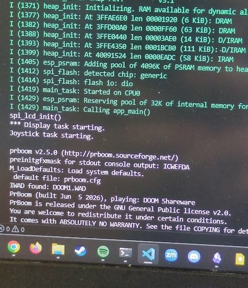
After banging my head against the wall with C code for hours, seeing the terminal finally spit out a successful boot sequence was massive. I immediately texted all my friends to tell them my project could run Doom.
POST GRADUATION
The PAK was finished up! I presented the PAK on the first day of presentations for Fab Academy 2026 along side my Kannai colleagues. My Fab Academy journey in Japan was wrapping up, but my work on the PAK was not yet finished.
The PAK I presented was not perfect. There were so many things that needed to be reworked or redesigned entirely.
THE CASE
One of the biggest struggles with designing and fabricating the PAK was that early into the previous cycle, I bit the bullet on ordering PCBs without fully CADing out the rest of the design with system integration in mind. I felt I needed to get my hands on something right away and get a sense of the size and scale of the object before I finalized the case design. This was a bit of a mistake because I ended up having to bodge together aspects of the final case design. It may not be noticible to you, dear reader, but it is to me! And it constrained some of the things I could do with the ergonomics. Lesson learned, CAD out everything first, heck, even 3D print the circuit board footprint if you're worried about the real world alignments.
THE MEMBRANE BUTTONS
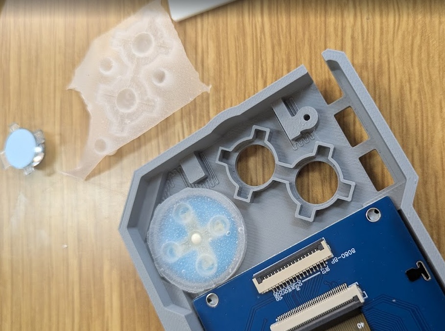
After passing around the PAK to show off to my friends, family and students, I noticed the D-PAD and A/B buttons, which are all actuated with a carbon pill silicone membrane cast dome button, started to become less responsive over time. I learned over time that this was due to the membranes shifting within the case, despite thinking I had the perfect fit. I noticed in teardowns of other electronic devices that use membrane domes that many of them had a silicone cast key to align and keep the membrane structure in the correct place, in addition to the perimeter keying. This change would require a drill hole included in the PCB and likely another modification to the final case design as well.
THE CARTRIDGE
One of the key elements I wanted to get perfect with the PAK was the cartridge. This was absolutely the most difficult to get right, especially because the slightest sub-millimeter change in a printed prototype results in a completely different feel for the cartridge. I thought that, prior to sending off the final high quality print to JLCPCB, that my design files were right were they needed to be. However, the presentation version of the PAK suffers from occasional misalignment with the cartridge pins. To fix this, I would need to redesign the cartridge. However, one of the biggest constraints with the cartridge was the size I had worked myself into. My cartridge was quite restrictive with the size and how it needed to slot with the push-push mechanisms. My problem was that the pins themselves were not at the right depth to make contact with the spring loaded pins on the motherboard (or, actually the bodge daughterboard that was added to correct alignment, another thing to fix in the SP version). That problem could not be corrected easily by just raising the floor of PCB holder in the cartridge would make the flash chip embedded in the cartridge bulge out. The top of the cartridge case was already as thin as I could get it.
I chose to write the OS for the PAK in MicroPython as it was a language I was more familiar with at the time, and something I wanted to develop more confidence with - so I could teach it to my students!
The big problem is that MicroPython has a lot of overhead for a device like this. The ESP32 struggled to handle the SPI bus of the cartridge and screen at the same time, and run complex code like a game where the screen needs to update often.
After swallowing my pride, I decided to explore what the PAK Operating System would look like if I chose the C++ route earlier in my project. I had resisted the idea of using Claude the entire Fab Academy cycle, but now that I had graduated, I figured I'd give it a go and see what all the hype was about.
Claude was able to take my whole code base in MicroPython and successfully rewrite it in C++ in a single prompt. I was floored. Instantly a 100% increase in performance. Of course, Claude found a lot of errors and bad code that I had stubbornly included in my MicroPython implementation and cleaned it up too, but I was amazed just how quick the OS worked now. The TFT display still had a bit of screen tearing, but it was much less noticeable.
As I mentioned earlier in week 21, the cartridge had issues making contact with the motherboard, a complete redesign of the circuit board was needed to address this. I simplified the design and reconfigured the routing of the traces to allow for a double-sided board that would mount the flash chip underneath, rather than getting in the way of the cartridge case top half.
I sent the gerber files to JLCPCB, as I don't have any way to make my own PCBs here in Toronto (no milling machine yet, but I'm trying to find one!)
Once the PCBs arrived, I made some modifications to the cartridge CAD file, and reprinted the enclosures on my Bambu A1 mini at home.
CODENAME: SPECIAL PLAYER
Throughout Fab Academy and creating the PAK, I was already thinking about the successor of the PAK, much like how the Game Boy received many successors and alternative models to improve or add quality of life features (Game Boy Light, Advance, Advance SP, etc.). I was already giddy to think about what features I would include in the PAK's successor. In homage to the Game Boy Advance SP, I chose to dub this successor project "CODENAME SPECIAL PLAYER".
Project SP is something I want to continue working on outside of Fab Academy to help build my skills and experiences creating consumer level products with home/hobbyist maker tools.
The big ticket items that I want to prioritize and try learning for this project include: creating a clamshell design with ribbon cables for the screen/hinge, an edge connector slot for the cartdige instead of a spring loaded latch mechanism, and a more robust pin-out that could feature up to 20 pins more expansive and thoughtful on-cartridge sensors.
BILL OF MATERIALS
Everything below is in Canadian Dollars.
| Part Name | Price | Unit | Forward Cost | Link |
|---|---|---|---|---|
| Motherboard PCB | $3.94 | 1/5 | $0.788 | JLCPCB |
| Controls PCB | $4.64 | 1/5 | $0.928 | JLCPCB |
| ESP32-WROOM-32D | $7.78 | 1/1 | $7.78 | DigiKey |
| 3.5 inch TFT Screen | $31.07 | 1/2 | $15.535 | AliExpress |
| Pogo Pins | $13.16 | 0/100 | $0.00 | Temu |
| 0.1uF Capacitor | $49.62 | 3/500 | $0.30 | DigiKey |
| 1uF Capacitor | $49.62 | 1/500 | $0.10 | DigiKey |
| 10uF Capacitor | $49.62 | 4/500 | $0.40 | DigiKey |
| 1K Ohm Resistor | $18.94 | 1/1000 | $0.02 | DigiKey |
| 1.2K Ohm Resistor | $18.94 | 1/1000 | $0.02 | DigiKey |
| 10K Ohm Resistor | $18.94 | 7/1000 | $0.11 | DigiKey |
| 100K Ohm Resistor | $18.94 | 2/1000 | $0.04 | DigiKey |
| Diode Schottky | $68.00 | 2/250 | $0.54 | DigiKey |
| JST Connector | $18.33 | 2/200 | $0.18 | Amazon JP |
| Switch Slide Right Angle | $32.05 | 1/25 | $1.28 | DigiKey |
| TP4056-42-ESOP8 | $6.55 | 1/10 | $0.66 | Amazon JP |
| RT9080-33GJ5 | $0.47 | 1/1 | $0.47 | DigiKey |
| LiPo Battery | $4.40 | 1/1 | $4.40 | Amazon |
| MOSFET (PCh, SOT23) | $140.90 | 1/250 | $0.56 | DigiKey |
| Button ESwitch | $0.04 | 2/2 | $0.04 | MadeInChina |
| Conductive Carbon Pills | $8.50 | 6/150 | $0.34 | Amazon |
| CH340E USB Serial | $4.77 | 1/1 | $4.77 | Akizuki Denshi |
| M2 Screws | $11.25 | 10/304 | $0.40 | Amazon JP |
| M2 Nuts | $11.25 | 4/304 | $0.17 | Amazon JP |
| Double Sided Tape | $17.40 | 1cm/2286cm | $0.01 | Amazon |
| SLA Resin | $15.40 | 2/2 | $15.40 | JLCPCB |
| Smooth-On Plastic | $75.99 | 5g/907g | $0.43 | Amazon JP |
| Clear Acrylic | $35.99 | 2cm^2/11482cm^2 | $0.01 | Amazon |
| W25Q128JVSIQ | $1.38 | 1/10 | $0.138 | AliExpress |
| Copper PCB Board | $11.35 | 7cm^2/60cm^2 | $1.32 | Amazon JP |
This puts the total cost of one PAK's raw materials at $55.68 Canadian Dollars, with the bulk of that price coming from the screen and the professionally manufactured resin prints. As for the costs with research and development included... well.. that might make the PAK one of the most expensive ways to play doom.
FILES
If you're interested in building a PAK yourself, here are all the files you need to get started.
All code is licensed under the GNU General Public License v3.0, or GPLv3.
All physical designs, 3D models, PCB schematics, and instructional materials are licensed under Creative Commons Attribution-ShareAlike 4.0 International, or CC BY-SA 4.0.
 PAK_cartridge.f3z
PAK_cartridge.kicad_pcb
PAK_cartridge.kicad_sch
PAK_case.f3d
PAK_controls.kicad_pcb
PAK_controls.kicad_sch
PAK_daughterboard.kicad_pcb
PAK_daughterboard.kicad_pro
PAK_motherboard.kicad_pcb
PAK_motherboard.kicad_sch
 pomodoro.py clock.py input_test.py my_page.py input_test.py doodle_jump.py flappy_bird.py snake.py