INTRODUCTION
It's my last week in Peru, and in order to make sure I get the full Peruvian experience (as my colleagues at ESAN like to say), I went ahead and got myself a case of gastroenteritis and spent most of this week in bed. Thankfully, after a visit to the ER for some antibiotics, I was able to recover quite quickly and managed to get 2 days of lab time. Nothing can stop me from making!
[x] Measure the power consumption of an output device.
[x] Document your work on the group work page and reflect on your individual page what you learned.
[x] Add an output device to a microcontroller board you've designed and program it to do something.

[x] For my students: Continue making some demonstrations of electronics interfacing!
You can also read about our group assignment at Fab Lab Kannai here. Once again, adding content here retroactively even though I wasn't in Japan yet. My group members in ESAN were not available and I do not have repo access to the ESAN page.
Ghost in the Machine
You might think that this week (Output Devices) would have a similar ring to last week's content (Input Devices), but we're really looking at a completely different world. However, one line that we'll return to from last week's documentation is a reminder that computers aren't magic. They interact with humans and the world around them "simply" through a process of binary signals and processing. Outputs, just like inputs, must come from an electrical signal. To actually "affect" the physical world, a computer requires an actuator, something that will turn that electrical signal into a different more perceptible form of energy, and these changes are often a lot simpler than the tricks we invent to get the signal to flow the other direction. I could group these signal changes into three groups:
-
Light. Converting electrical current into visible light. This can be achieved in something like an LED where electrons release energy as photons after dropping to a lower energy state through a semi-conductor material.
-
Sound. Converting electrical current into sound waves, physical pangs of air pressure. We spoke a little bit about how piezoelectric crystals can oscillate in the presence of a current, essentially creating a little current controlled drum.
-
Magnetic. Converting electrical current into magnetic fields, which are mostly used to make things move, like a motor! Applying a current to a coiled wire induces a magnetic field, which can attract or repel certain magnetic materials. Hook this up in a circle and alternate which coils are on/off, and you've got something that spins!
-
Heat. The secret fourth group. Often unwanted. You gotta remember that entropy really wants to take all of this energy we're using and just push it out into the universe as heat. Heat will be a byproduct of all of the above processes, as energy conversion is never 100% efficient. With electronics, heat is generally something that is telling you you're doing something wrong. You've either got a short or your hardware is pulling too much current.
Data Lines (Reviewed)
To continue our interactive demonstrations from last week, let's review some of the ways we can actually "send" different voltages down our microcontroller pins, and different ways that signal can affect change through an actuator.
Once again, I'm using a combination of Illustrator, HTML/CSS and Gemini to create these simulations. I create the nonstandard SVG shapes in Illustrator, export them as .SVGs (which is just a series of vector definitions), add them to a little HTML div that inherits the CSS of my site, and then ask Gemini to bring them to life with Javascript. Here's the prompt:

You are an expert front-end developer and web animation specialist. Help me write vanilla JavaSript (not React) to animate several core concepts in electrical engineering for a widget on my website. I will provide you with a prompt that describes the concept as I want to convey it, how the user interacts with it, state machines to consider, the SVG objects and their names, the HTML layout of the site that I've already configured, and some CSS properties of the interactive components. [Insert individual prompt here]
➔ DigitalWrite
When we use a command like digitalWrite(HIGH), we are telling a microcontroller to open an internal gate that connects the pin directly to its 3.3V power source, pushing electrons out into the circuit. When we call digitalWrite(LOW), it connects the pin to Ground (0V), preventing that flow. By toggling between these two absolute states, we can directly control simple output devices when we wire them in to our circuits. Importantly, whatever we're wiring still needs needs a proper path to ground (or Vcc if it's using a common anode like my RGB LED example coming up)
AI Prompt Attribution
➔ PWM
As Neil pointed out in this week's lecture, we can't really do an "analogWrite", that is: send a voltage reliably somewhere in between 0V and 3.3V. Microcontrollers are strictly digital devices, meaning they can only push out a full 3.3V (HIGH) or 0V (LOW). However, they can fake an analog signal using a technique called Pulse Width Modulation (PWM).
By turning a digital pin ON and OFF incredibly fast (often thousands of times a second), the microcontroller controls the percentage of time the pin spends at 3.3V. To human eyes, an LED driven high 50% and low 50% of the time doesn't look like it's flashing, it simply looks like it is receiving half the voltage, making it appear half as bright. This optical and electrical illusion allows us to fake the values in between for a lot of devices, and as you'll see later, something we got to capture on the oscilloscope!
AI Prompt Attribution
➔ I2C
Inter-Integrated Circuit. As we discussed last week, I2C uses two wires to packages every command with a specific hardware address, and it works in both directions, which means it is half-duplex. Output devices can (and should) talk back to the microcontroller to confirm receipt of any instructions.
I2C also solves the problem of running out of pins on your microcontroller by allowing you to run devices on the same bus, because each device will only listen for it's address before reading what's inside the package. Because these devices communicate by pulling the line to ground (0V) rather than pushing voltage out, the bus requires pull-up resistors to keep the default state HIGH.
AI Prompt Attribution
➔ SPI
Serial Peripheral Interface. Again, this works in a similar way to I2C, but instead of addressing individual components in binary, we directly wire them up with something called a "Chip Select" pin for each device. However, instead of using the same SDA line, we have a dedicated talk/receive line, making it "full-duplex".
AI Prompt Attribution
Probing
This was technically a requirement of last week's assignment, but I'm bringing it forward to this week because I feel it's a great bridge between what I learned about data transfer and power. Here, I have a simple script to oscillate the level of the backlight on a 3.5" TFT screen.
import time
import math
import board
import busio
import displayio
import terminalio
import pwmio
from adafruit_display_text import label
from circuitpython_st7796s import ST7796S

print("Starting...")

displayio.release_displays()
spi = busio.SPI(clock=board.D8, MOSI=board.D10, MISO=board.D9)
display_bus = FourWire(spi, command=board.D2, chip_select=board.D3, reset=board.D1)
display = ST7796S(display_bus, width=480, height=320, rotation=0)

splash = displayio.Group()
display.root_group = splash
text_area = label.Label(terminalio.FONT, text="OSCILLOSCOPE TEST", color=0xFFFFFF, scale=3)
text_area.anchor_point = (0.5, 0.5)
text_area.anchored_position = (240, 160)
splash.append(text_area)

backlight = pwmio.PWMOut(board.D6, frequency=1000, duty_cycle=0)

angle = 0.0
speed = 0.05

while True:
    brightness = (math.sin(angle) + 1.0) / 2.0
    backlight.duty_cycle = int(brightness * 65535)

    angle += speed
    if angle > math.pi * 2:
        angle = 0.0

    time.sleep(0.01)
Then I'm able to wire up the leads from the oscilloscope to the ground and backlight pin to measure this oscillation. We've got a GDS-11521A-U here in the lab. Set up was simple. Get it plugged in, attach the lead to COM1, and adjust the volts dial to a suitable range (we're looking at 0 to 3.3V), then have it record the signal at a suitable threshold (halfway or around 1.52V is good).
Power Consumption
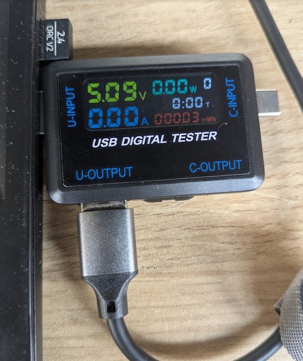
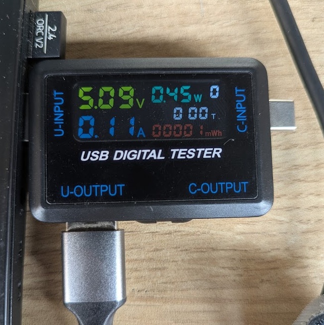
Part of the Fab Academy curriculum this week includes talk about power. Our assignment this week, in part, asks us to measure the power draw of a particular output device. This is an excellent opportunity to start thinking about the power requirements of my final project, the PAK. I brought a little USB power analyzer with me from Canada that intercepts your USB power interface and acts as a little multimeter in the power delivery circuit. I could hook this up to my power source (in this case, my computer's USB-A port) and wire the XIAO ESP32-S3 on the other side, and begin tinkering with it.
The microcontroller itself doesn't seem to draw a lot of current on it's own, at least under a weak load. My analyzer had a hard time picking up much of anything when it was running some simple Circuit Python scripts with no other loads. We'll be able to do some finer testing once I have scripts that really put this thing under load, but from what I've read, the max it will pull won't be much more than 100mA.
I knew that the screen would be the next (or largest) source of power draw, especially since I'm opting to use a much larger 3.5" TFT rather than the standard 0.91" models that are being stocked in the Fab Inventory. In my testing, it seems as though the backlight is the largest source of power draw, which makes sense considering it's the part that is pushing the most light out. I'm prototyping the PAK to also use 1-2 RGB LEDs for status indicators on the device, those will also draw an amount to consider.
The other components on the stock PAK (shift register, buttons, flash memory, etc.) draw a negligible amount of power. The big variability is going to be from cartridges that require their own processing or are driving some auxiliary output device. The big examples I can think of would be the DFplayer cartridge, which has it's own pre-amp to drive a speaker (but I think I might just use a line level input for headphones exclusively) and the camera module.
This would let me do a bit of napkin math to calculate theoretical battery life of the PAK.
ESP32-S3 ~ 100mA
TFT Screen ~ 110mA
Indicator LEDs ~ 50 mA
Intensive Cartridges ~ 50mA
TOTAL: 260-310 mA
Using a typical 2000mAh LiPo battery would put me at 2000mAh/300mA = ~6.6 hours of battery, which is totally acceptable given this device isn't meant to be always on. You're only meant to power it on when you want to intentionally use something!
Project Testing
➔ TFT Screen
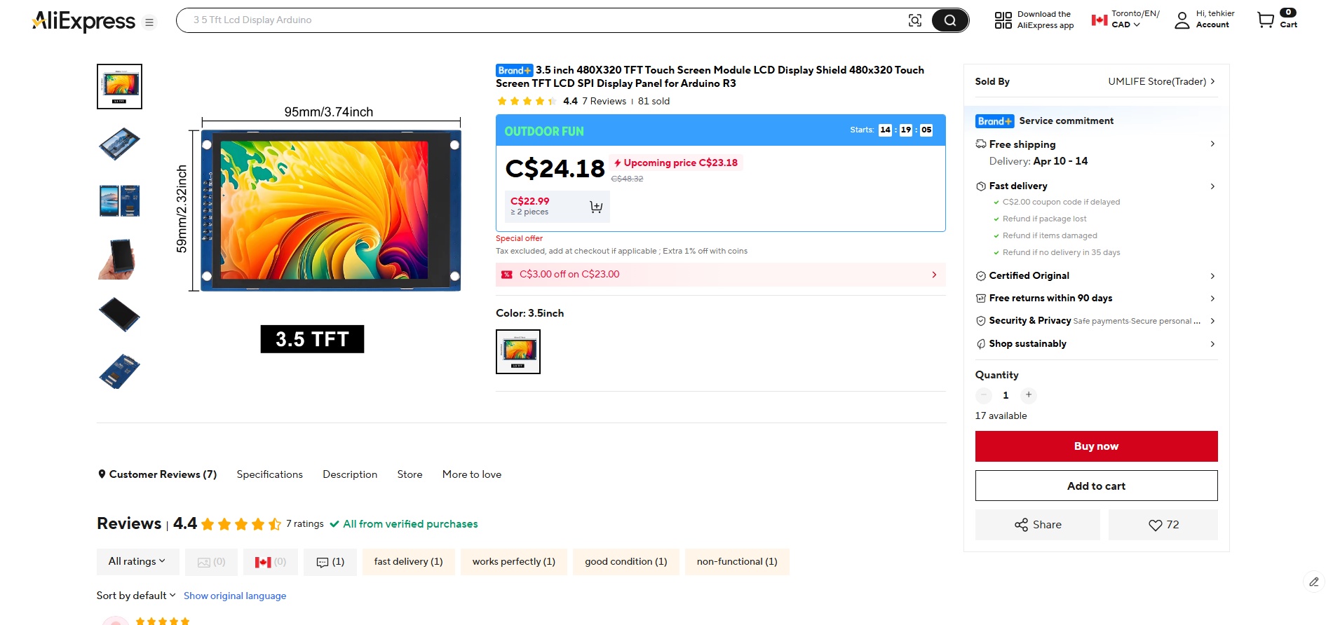
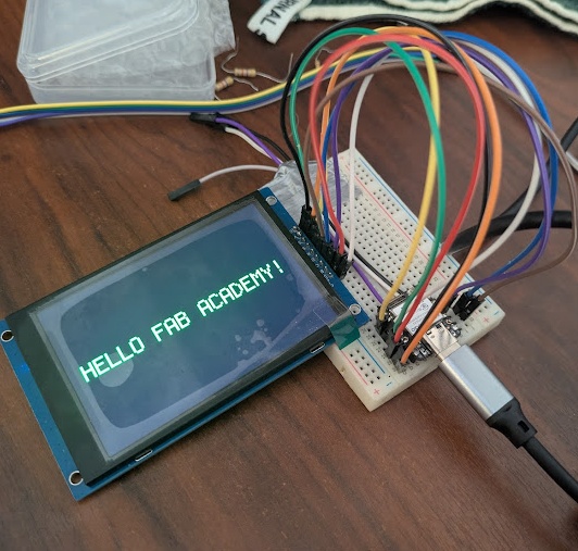
I had done tests on smaller screens before, including for a little circuit I continue to use every single day here at ESAN to help me take breaks, but I knew I would need something larger for my final project. In the early weeks of my time here at ESAN, I placed an order on AliExpress for this 3.5" TFT Screen so I could begin development on the PAK at the native resolution. Apart from trying to get a big circuit board working in Week 08, I haven't really had the time to actually test out the screen and get it working.
Despite there being no documentation for this particular screen (or at least I could not find anything that matched this specific one), writing code for it is quite simple using the adafruit circuitpython_st7796s library. I'm still having some compatibility issues with Circuit Python (it's making me regrettably want to switch to C++), but I was able to fix it by trying to import FourWire from displayio.
import board
import busio
import terminalio
import displayio

try:
    from fourwire import FourWire
except ImportError:
    from displayio import FourWire

from adafruit_display_text import label
from circuitpython_st7796s import ST7796S

print("Starting...")
displayio.release_displays()
spi = busio.SPI(clock=board.D8, MOSI=board.D10, MISO=board.D9)

#pins
tft_cs = board.D3
tft_dc = board.D2
tft_rst = board.D1

display_bus = FourWire(spi, command=tft_dc, chip_select=tft_cs, reset=tft_rst)
DISPLAY_WIDTH = 480
DISPLAY_HEIGHT = 320

display = ST7796S(display_bus, width=DISPLAY_WIDTH, height=DISPLAY_HEIGHT, rotation=180)
splash = displayio.Group()
display.root_group = splash

text_area = label.Label(
    terminalio.FONT,
    text="HELLO FAB ACADEMY!",
    color=0x00FF00,
    scale=4
)

text_area.anchor_point = (0.5, 0.5)
text_area.anchored_position = (DISPLAY_WIDTH // 2, DISPLAY_HEIGHT // 2)
splash.append(text_area)

print("Text is on screen")

while True:
    pass
and here it is working!!
➔ RGB LED + Light Pipe
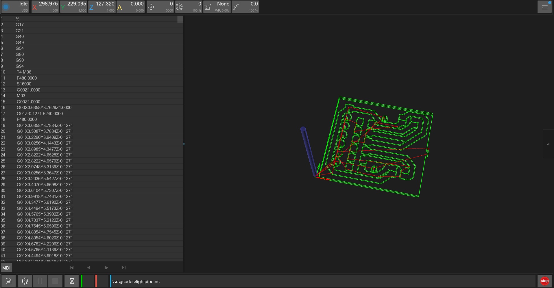
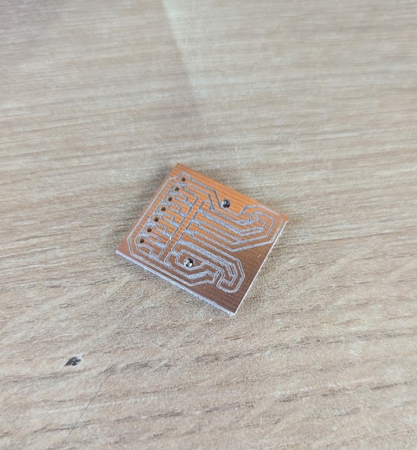
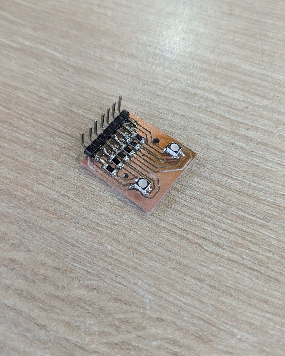
I mentioned earlier that I wanted to include an indicator LED on the PAK. This gets me closer to achieving the retro inspired design language of the devices from my childhood, but also helps me with a critical aspect of development - troubleshooting. It's super important to have multiple places to you can listen to the microcontroller from. Typically, I code my projects so that I am ALWAYS pushing statements to the terminal whenever I am expecting an action in the real world. This will get tough when I am looking to troubleshoot the hardware untethered and on-the-go, so implementing a hardware LED is going to be important.
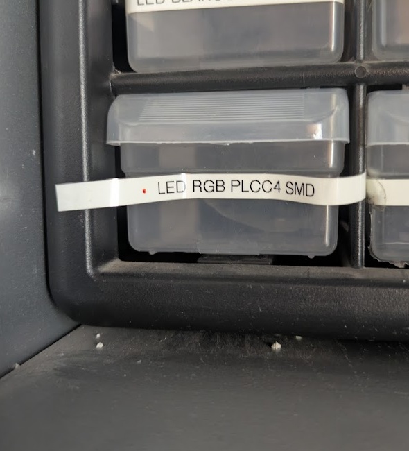
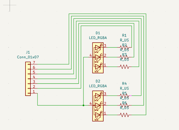
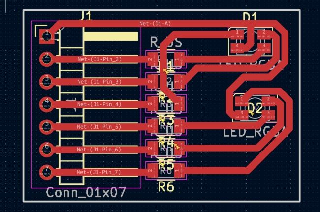
I created a board in KiCAD to help me test. I included two SMD RGB LEDs for fun, though in developing this, I realized just how many GPIO pins would be needed to properly control this. I would probably stick to a single LED in my final project. The alternatives would be to include some kind of I2C daughterboard for LED handling, use another one of my shift registers (which still requires 3 pins) or a neopixel board - all of which overcomplicate things a lot for just two LEDs.
With a bit of simple code to test the full spectrum of HSV values (rather than RGB which often just ends up giving you a bunch of bright whites as you're mixing). This function works by translating the RGB values of each HSV section into 16-bit PWM values, which are actually inverted since the LED uses a common anode (65535 is OFF, 0 is totally on).
import time
import board
import pwmio

print("Starting...")

led1_b = pwmio.PWMOut(board.D0, frequency=5000, duty_cycle=65535)
led1_g = pwmio.PWMOut(board.D1, frequency=5000, duty_cycle=65535)
led1_r = pwmio.PWMOut(board.D2, frequency=5000, duty_cycle=65535)
led2_b = pwmio.PWMOut(board.D3, frequency=5000, duty_cycle=65535)
led2_g = pwmio.PWMOut(board.D4, frequency=5000, duty_cycle=65535)
led2_r = pwmio.PWMOut(board.D5, frequency=5000, duty_cycle=65535)

led_1 = (led1_r, led1_g, led1_b)
led_2 = (led2_r, led2_g, led2_b)

def set_color(led_tuple, r, g, b):
    led_tuple[0].duty_cycle = 65535 - int((r / 255.0) * 65535)
    led_tuple[1].duty_cycle = 65535 - int((g / 255.0) * 65535)
    led_tuple[2].duty_cycle = 65535 - int((b / 255.0) * 65535)

def hsv_to_rgb(h, s, v):
    if s == 0.0:
        return (int(v * 255), int(v * 255), int(v * 255))
    i = int(h * 6.)
    f = (h * 6.) - i
    p = v * (1. - s)
    q = v * (1. - s * f)
    t = v * (1. - s * (1. - f))
    i %= 6
    if i == 0:
        return (int(v * 255), int(t * 255), int(p * 255))
    if i == 1:
        return (int(q * 255), int(v * 255), int(p * 255))
    if i == 2:
        return (int(p * 255), int(v * 255), int(t * 255))
    if i == 3:
        return (int(p * 255), int(q * 255), int(v * 255))
    if i == 4:
        return (int(t * 255), int(p * 255), int(v * 255))
    if i == 5:
        return (int(v * 255), int(p * 255), int(q * 255))

hue_1 = 0.0
hue_2 = 0.5
speed = 0.005

while True:
    r1, g1, b1 = hsv_to_rgb(hue_1, 1.0, 1.0)
    r2, g2, b2 = hsv_to_rgb(hue_2, 1.0, 1.0)
    set_color(led_1, r1, g1, b1)
    set_color(led_2, r2, g2, b2)

    hue_1 += speed
    hue_2 += speed

    if hue_1 > 1.0:
        hue_1 -= 1.0
    if hue_2 > 1.0:
        hue_2 -= 1.0

    time.sleep(0.02)
After milling and soldering the board, the result is this nice little breakout test system that I can plug directly into the XIAO.
Except, I really don't like the look of a bare SMD LED! They are too bright and leak a lot of light if you're trying to get them positioned in a plastic 3D printed case. The solution: create 3D printed "light pipes" out of translucent and opaque filament. I tried some different designs for the 3D printed light pipes to gain some information.

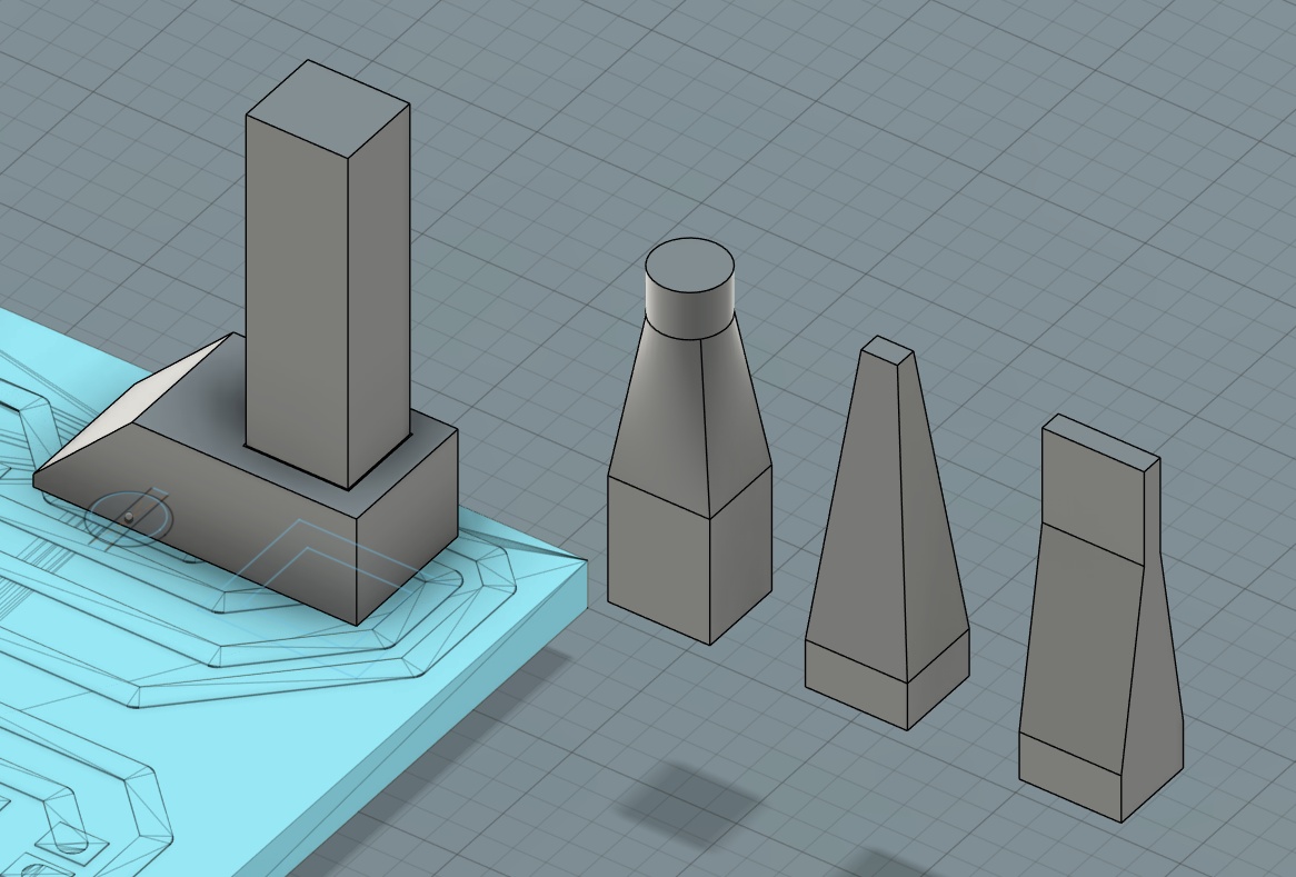
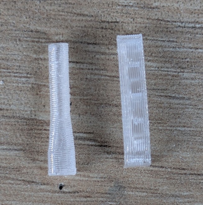
The idea is to funnel the light out to where you want it, ideally away from the PCB that is deep inside of the case, and also diffuse the light so that it's a little nicer to look at!
What I learned here is that you need to force your light pipe to be printed with layer lines running parallel to the direction you want the light to run. You can see here in the pictures that the pipes that were printed standing up block a fair amount of the light early and it doesn't make it to the end, you can see it even better in the pipe that "bends", changing the layer line direction.
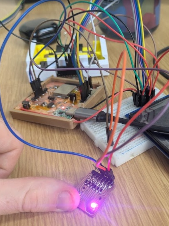
Here's a photo of the same RGB LED board being used later on a dedicated ESP board (the breadboard in the picture is not part of the circuit, it's being used to hold a TFT display).
➔ Audio DFPlayer
One of the stretch goals for the PAK is to create a little walkman-inspired MP3 player cartridge. I learned this week in the lecture that there is a perfect little daughter board, called the DFplayer, that can handle this over a super simple UART connection to the microcontroller. Testing this was a lesson in the fragility of hardware though...
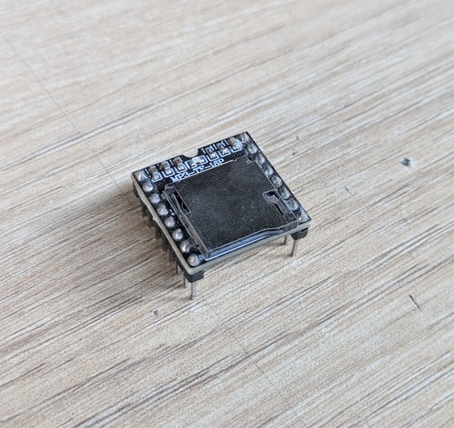
The module takes a TF (microSD) card that must be formatted in FAT32. By default, it handles very simple .mp3 playback assuming you've got the file structure figured out. I had to name my files 0001.mp3, 0002.mp3, etc. to get it to work, but I'm sure with a little more tinkering and code, I could get it to recognize and parse more complex file system information.
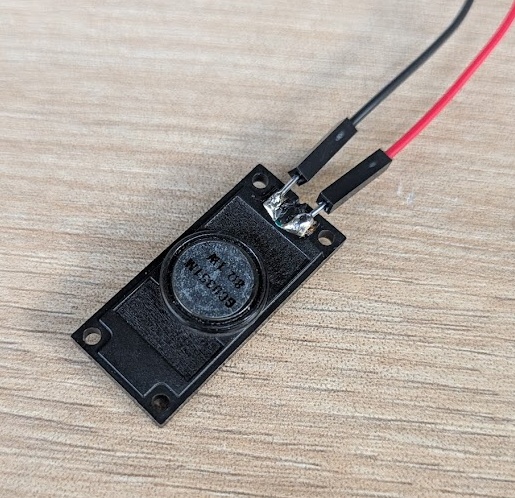
You wire up the DFplayer with pretty much just RX and TX lines. You do need a resistor on the RX serial line to bring down the 5V logic noise from the device to the 3.3V that the XIAO needs. ESAN didn't have any 3.5mm headphone jacks for me to test a line level signal on, so I soldered leads on a simple little 1W 8-ohm speaker and wired it to the SPK+/- pins on the DFplayer.
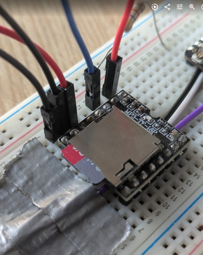
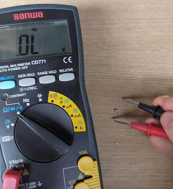
And it worked!!! I was eager to test different files on it, so instead of getting photos/videos, I swapped out the card and plugged it back in, only to find that it wouldn't power on. I probed some of the pins to check continuity... before I shorted one of the pins with the 5V signal, instantly melting the onboard chip and releasing the magic smoke.
Destroying ESAN's only DFplayer in inventory... Oops.
Conclusion
This week definitely didn't start the way I wanted it to... haha. Output devices turned out to be a lot more satisfying than I expected, and it was nice to ideate beyond just the screen for my final project and think about what other kinds of cartridges I could design that were more "output" focused. Seeing my expensive 3.5" TFT finally on with some of my own code felt like a proper step towards getting my final project finished, especially since I'd been sitting on the screen for weeks without a reason to wire it up.
I’m also genuinely glad I took the time to mess around with the 3D-printed light pipes - it inspired me to think of fabrication ideas for my final project more.
Next time, I’ll be much more intentional with my probing (RIP again to the DHplayer) - and make sure to take pictures before I pop the magic smoke. At least the data I gathered on power consumption and PWM logic gives me a clear roadmap for how the PAK is actually going to function once it's off the USB tether and running on a battery.