
Week 10
Week 10: Output Devices
I built output-device experiments around the glasses system, including a 3D PCB concept with display, buzzer, and LED, then worked through milling, soldering, and display issues.
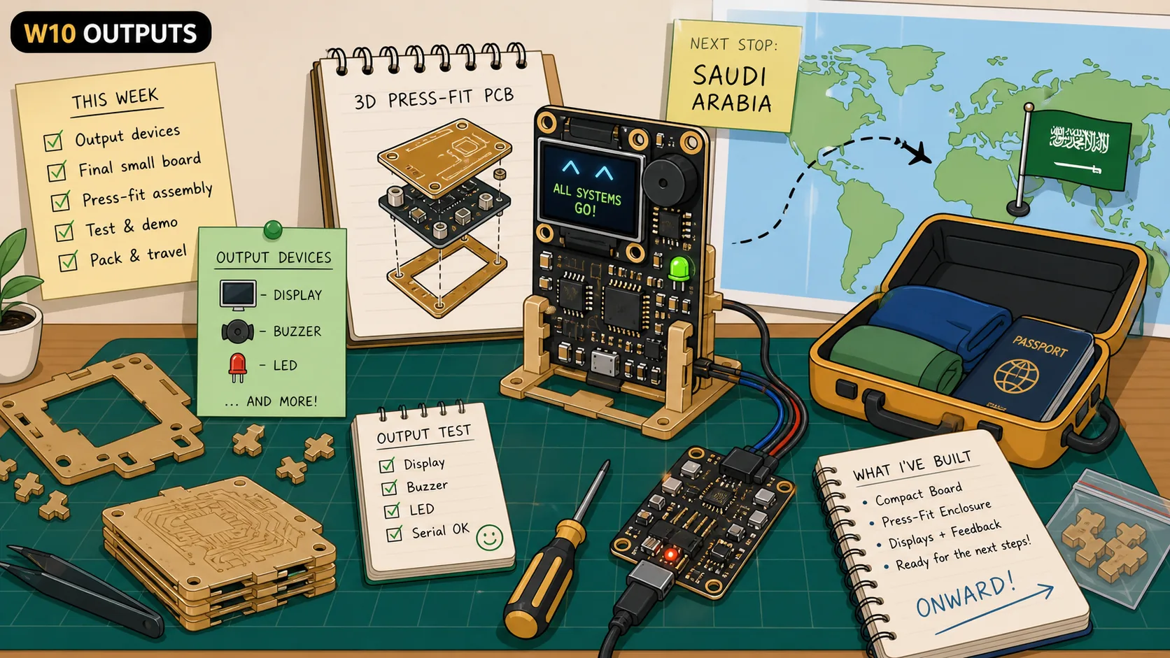
This week, I wanted to start experimenting with a custom PCB for my glasses. I started by experimenting with creating a 3D PCB where two "separate" PCBs press-fit into each other and get soldered into one that contained an LED, a buzzer, and a display.
Along the way, I needed to pivot slightly to get the assignment done, but will get to recreating it depending on what I'll need for my final project. :)
During this week, I also came back to Saudi to reunite with my family before flying to Japan to complete my journey at FabAcademy, some parts of this assignment was completed in Japan :D

Back home in Saudi with friends!
Jump to this week's checklist
Group Assignment: Measuring the Power Consumption of an Output Device
The group assignment this week was about measuring how much power an output device actually pulls. The full group write-up is linked above.
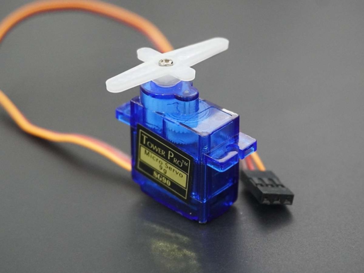
We tested a Tower Pro SG-5010 servo motor, which is a small hobby servo rated for 4.8V to 6V. We ran it on 5V from a Pico W using the standard Arduino Servo library Sweep example, which just walks the shaft from 0 to 180 degrees and back, over and over.
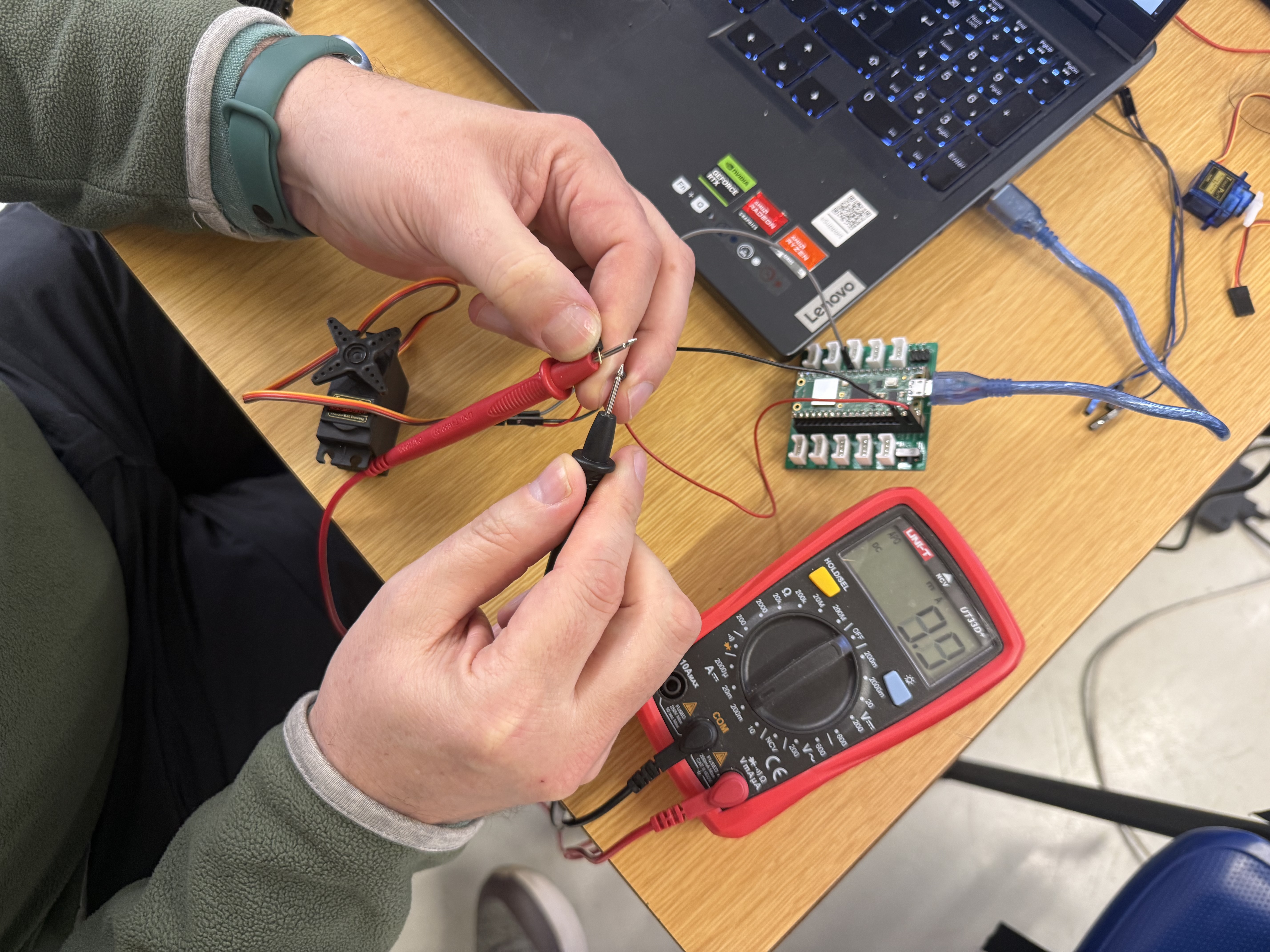
To measure current, we broke into the red power wire and put the multimeter in series, set to the 200 mA range. You have to break the circuit and let current flow through the meter itself. Different from voltage where you just probe across two points.
The numbers we got were:
About 10 mA when the servo was just holding or moving steadily
About 20 mA at the moments the servo changed direction
Up to 60 mA when we physically blocked the shaft and forced a stall
The control signal wire, measured separately, drew less than 1 mA.
The stall current being 6x idle is the number that stuck. Budget only for the idle case and the first time the shaft gets jammed, your regulator gets hot.
Voltage alone doesn't tell you much. Measure current, not just voltage.
For the rest of the week, I wanted to test an output device I'll be using in my final project, a DISPLAY xD.
Learnings
Output devices are the part where things get physical. Light, motion, sound, display. The session covered a lot of ground, LEDs to brushless motors to soft robots made from inflatable silicone. Neil also gave me direct feedback on my EEG final project during the session, which I'll note at the end.
Electrical Safety
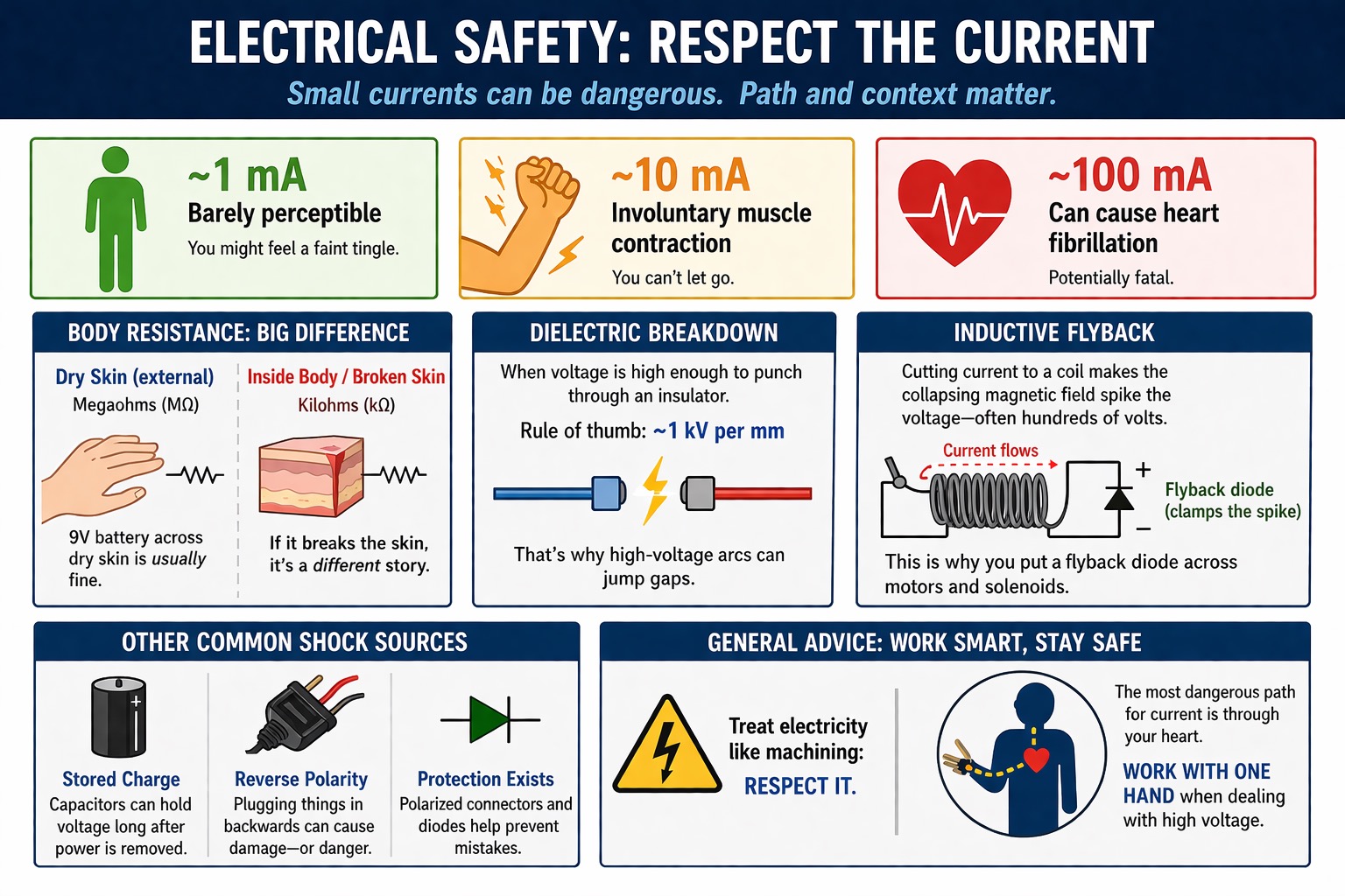
~1 mA: barely perceptible
~10 mA: involuntary muscle contraction, you can't let go
~100 mA: can cause heart fibrillation
Your body's resistance depends a lot on the situation. Externally with dry skin it's in the megaohms. Internally it drops to kilohms.
A 9V battery across dry skin is fine, but Neil pointed out that if it pokes through broken skin it's a completely different situation.
Dielectric breakdown happens when the electric field is strong enough to overcome a material's dielectric strength and make it conductive. For dry air at normal pressure this is about 3 kilovolts per millimeter, which is why high-voltage sources can create arcs that jump small gaps.
He talked about inductive flyback, where cutting current to a motor coil makes the collapsing magnetic field spike the voltage. That's the main reason you put a flyback diode close to motors and solenoids.
Capacitors holding charge after power is disconnected are another common shock source. And reverse polarity (plugging things in backwards), which is why polarized connectors and protection diodes exist.
General advice was to treat it like machining safety. The most dangerous path for current is through your heart, so always work with one hand when dealing with high voltage.
Power
USB is basically the "OP cable" for Fab Academy projects, Neil's words. 5V, everywhere. He showed a USB multimeter that you plug inline to see real-time current draw, which seems really useful for debugging.
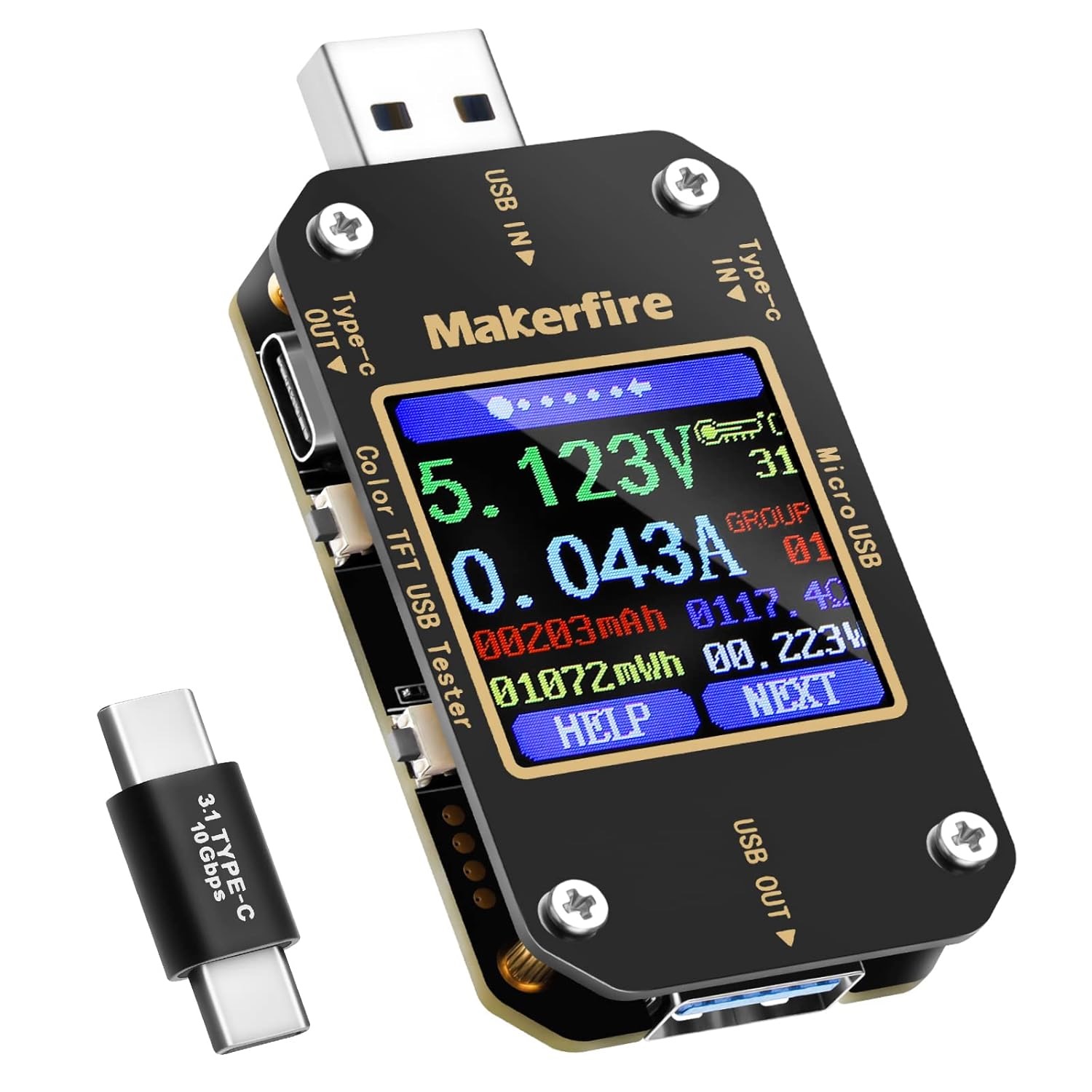
USB has gotten a lot more interesting on the power side with PD (Power Delivery). Instead of just outputting 5V, a charger and device negotiate over the cable and agree on a voltage and current that works for both. So the same cable can carry 9V for a phone charge or 20V for a laptop.
There are small inline gadgets that let you actually see what's going on — something like this USB tester that you plug between a charger and a device and it shows you every voltage and current profile the adapter advertises, and what the device actually requested.
For more power, bench supplies let you set both voltage and current limits so you don't fry things while developing.
LiPo batteries have great energy density but need dedicated charge controllers, you can't just wire them up. Some batteries need specific charging models to control them properly.
Neil also brought up wireless power and mentioned a paper he co-authored about shoes that recover energy from walking.
Watts = volts x amps. You need the current, not just the voltage. Wire gauge matters too because thin wires have more resistance and waste power as heat.
LEDs
More interesting than I expected, it is a light what's more to it, lol?
PWM dimming, you switch fast enough and your eye reads it as dimmer. The LED is technically flashing but at hundreds of Hz so it blurs. If you wave it quickly you can actually see the on/off pattern because the motion separates the flashes.
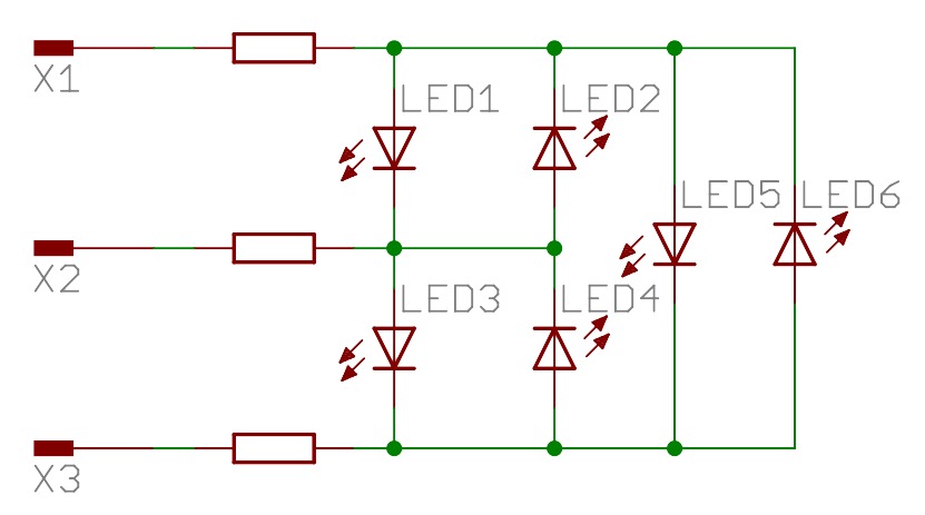
Charlieplexing lets you drive N x (N-1) LEDs from N pins. LEDs only conduct one way, and a pin set to input just drops out of the circuit, so you can selectively address individual LEDs with shared wires. Neil mentioned he just wrote his own library for this one.
Addressable LEDs (WS2812B/NeoPixels) have a built-in driver chip per pixel, single data wire, chain them.
Very bright LEDs exist that pull a lot more milliamps. For those you need a MOSFET since microcontroller pins cap around 20 mA. You generally switch MOSFETs fully on or fully off. If you put a gate voltage somewhere in between you get heat problems.
For high-power motor drives, IGBTs have been common over standard silicon MOSFETs. MOSFETs have Rds(on), a small resistance even when fully on. Their power loss is I² × R, so at high currents even a tiny resistance becomes a heat problem.
IGBTs are a MOSFET/bipolar hybrid that swaps that for a roughly fixed forward voltage drop, so conduction loss scales more like V × I instead, which works out better at high currents and voltages. The tradeoff is switching speed, IGBTs are slower due to minority carrier behavior.
Not all MOSFETs are the same material though. Standard ones are silicon (Si). Another type is the SiC MOSFETs that use silicon carbide, a harder wide-bandgap material that handles higher voltages and temperatures and switches faster with lower losses, which is why modern EV inverters are shifting toward them over IGBTs.
Displays
Display types mostly differ in how they actually produce the image, how you talk to them, and what they're built for.
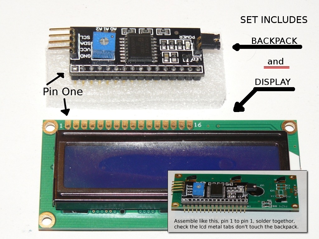
Character LCDs (the HD44780, usually 16×2 or 20×4) don't emit any light on their own. They just modulate ambient light or a backlight sitting behind them.
They are easy to drive and great for simple text menus, but that's about all they're good for. Pairing one with an I2C backpack (PCF8574) is common because it cuts the pin count way down.
A small note: I2C backpacks aren't universally compatible because the LCD modules can have slightly different pinouts from each other.
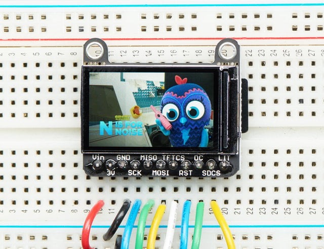
Graphic OLEDs like the SSD1306 work differently. Each pixel emits its own light, so true black is just a pixel that's off. That gives you great contrast and crisp text/icons in a tiny package.
The tradeoff is burn-in risk over time, and the brighter your image the more power it pulls since every lit pixel costs something. I will be most likely using a color version of this in my final project.
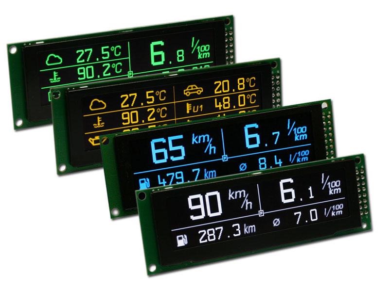
Color TFT-LCDs (ST7735, ILI9341, etc.) have a constant backlight behind the panel and the pixels work as color filters controlling how much gets through.
They are good for full-color graphics and higher resolutions, but blacks look grayish because light leaks through even when a pixel is "off," and the backlight runs all the time regardless of what's on screen. They are usually driven over SPI.
E-ink (like the ones on Kindles) only draws power when the image changes. Once it updates it holds whatever's on screen indefinitely with no power at all. It reads great in sunlight, but its refresh is slow and you get ghosting if you're not careful, so anything animated won't work very well.

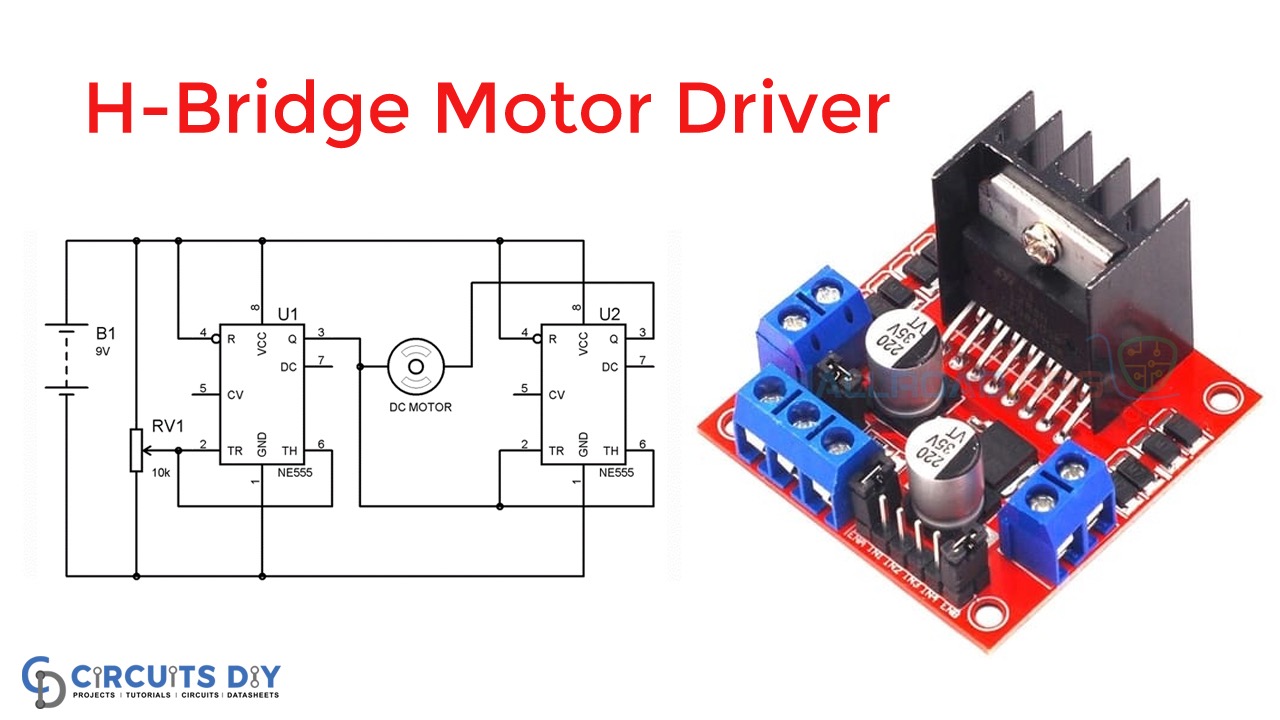
DC Motors and H-Bridges
To reverse a DC motor you reverse the current direction. An H-bridge handles this with four transistors in an H shape, switch different pairs and current flows either way.
Low-side switching is usually done with N-channel MOSFETs, while high-side switching can use P-channel MOSFETs for simplicity or N-channel MOSFETs with a gate driver, charge pump, or optocoupler. The gate needs to sit above the source, which is already at the high rail, so you need something to bootstrap the voltage high enough.
In practice, it's often easier to use a dedicated motor-driver IC like the TB67H451AFNG, which integrates the power stage and protection circuitry and is rated for up to 50 V and 3.5 A.
Flyback diode across the motor is needed since the collapsing field creates a voltage spike. PWM speed control is basically the same idea as LED dimming, just vary the duty cycle.
Gearing trades speed for torque (this adds backlash/percision loss). If a motor stutters, the symptom is usually not enough motor capacitance.
Servos
DC motors with built-in position feedback. 50 Hz PWM, 1 to 2 ms pulse width sets the angle. Typically 0 to 180 degrees. Continuous rotation (360°) versions exist too, but they don't control position. The PWM controls speed and direction instead.
They draw current spikes so they need their own regulator.
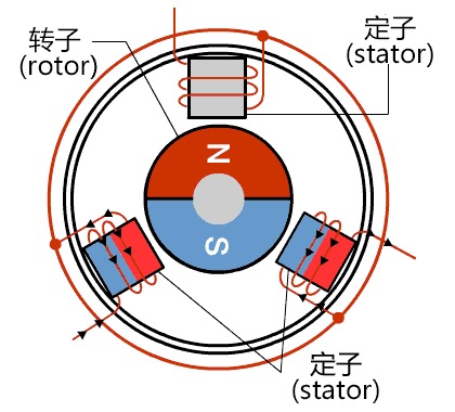
Brushless DC (BLDC)
Used in drones, electric cars, modern appliances. More efficient and no brushes wearing out. Kv rating is RPM per volt unloaded (1000 Kv at 12V = 12,000 RPM). Good for smooth continuous motions. Types: inrunner, outrunner (higher torque), pancake, fan, gimbal.
You send PWM to an ESC and it runs the motor, handles all the three-phase switching for you.
For very high currents like EVs, MOSFETs get replaced by IGBTs because Rds(on) losses become too large. MOSFETs work through resistance, and at hundreds of amps that means massive transistors and massive heat.
Steppers
Precise discrete steps, 1.8 degrees per step (200 steps per revolution). Specified by step angle, holding torque, and current/voltage ratings. You identify the wires by their coil pairs.
The simplest way to drive one is two H-bridges, one per coil pair, varying the current between them. Dedicated drivers like the DRV8428 reduce this to just step and direction signals.
Microstepping divides each full step for smoother motion. Sinusoidal stepping keeps total power uniform and makes the motion smoother, which matters for CNC applications. NEMA17 is standard in Fab Lab machines.

Audio
I2S is like I2C but for audio. PWM through a MOSFET to a speaker is simplest option.
I2S digital audio with something like the MAX98357A, takes digital audio in and drives a speaker directly.
MP3 playback with the DFRobot DFPlayer Mini (DFR0299), plays files off an SD card.
Wavetable synthesis, store samples in a lookup table and vary the playback rate for pitch. You can synthesize basically any waveform this way, and Neil seemed particularly into this one.
Other Actuators
Solenoids, electromagnetic plungers for linear push/pull.
Shape memory alloys, pass current through the wire to heat it and it contracts.
Piezoelectrics, voltage causes physical deformation (or deformation generates voltage, works both ways).
Soft robotics, a colleague of Neil's at Harvard created this field. Inflatable and pneumatic systems that create motion through air pressure.
Artificial muscles, including fishing line actuators and conducting thread.
Neil also mentioned an x-ray microscope that could make movies, which was tangential but cool.
Designing the 3D PCB with Display, Buzzer, and LED
This week, I wanted to experiment with design of my board while including aspects of my final project like a buzzer and a display.
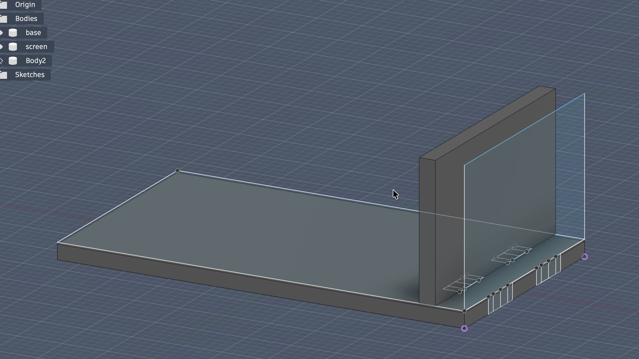
The first design I had in mind was of 2 boards that press-fit together creating sort of a "3D PCB." The goal of this experiment was to see how practical would it be to have the main board on the temple of the glasses and the display sticking out from another board that press fits into the main board.
This was intentional for making enough horizontal distance from the display to the prism and then to my eye.
Designing the Board on Fusion360 and KiCad
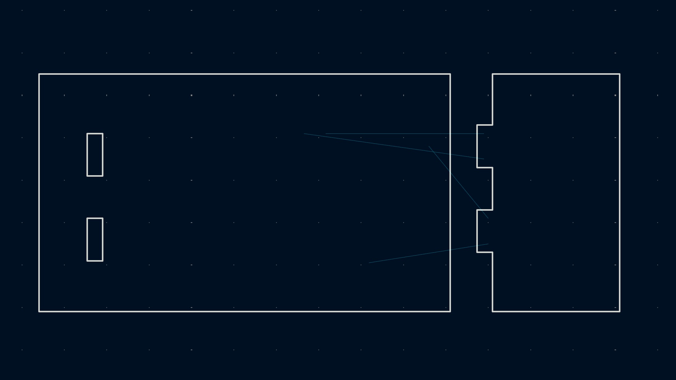
The design in Fusion was primarily to visualize how the press-fitted board looks like. I added different "marker" lines so when I import the sketches designs to KiCad, I'd have a guide how I would route the traces from the smaller board to the bigger one.
Of course, I measured everything to ensure there is space for all the different parts of my design and it would fit inside our copper board.
I exported it as DXF and imported it into the KiCad PCB editor.
Then, I started placing all my components in the Schematic and connected everything.
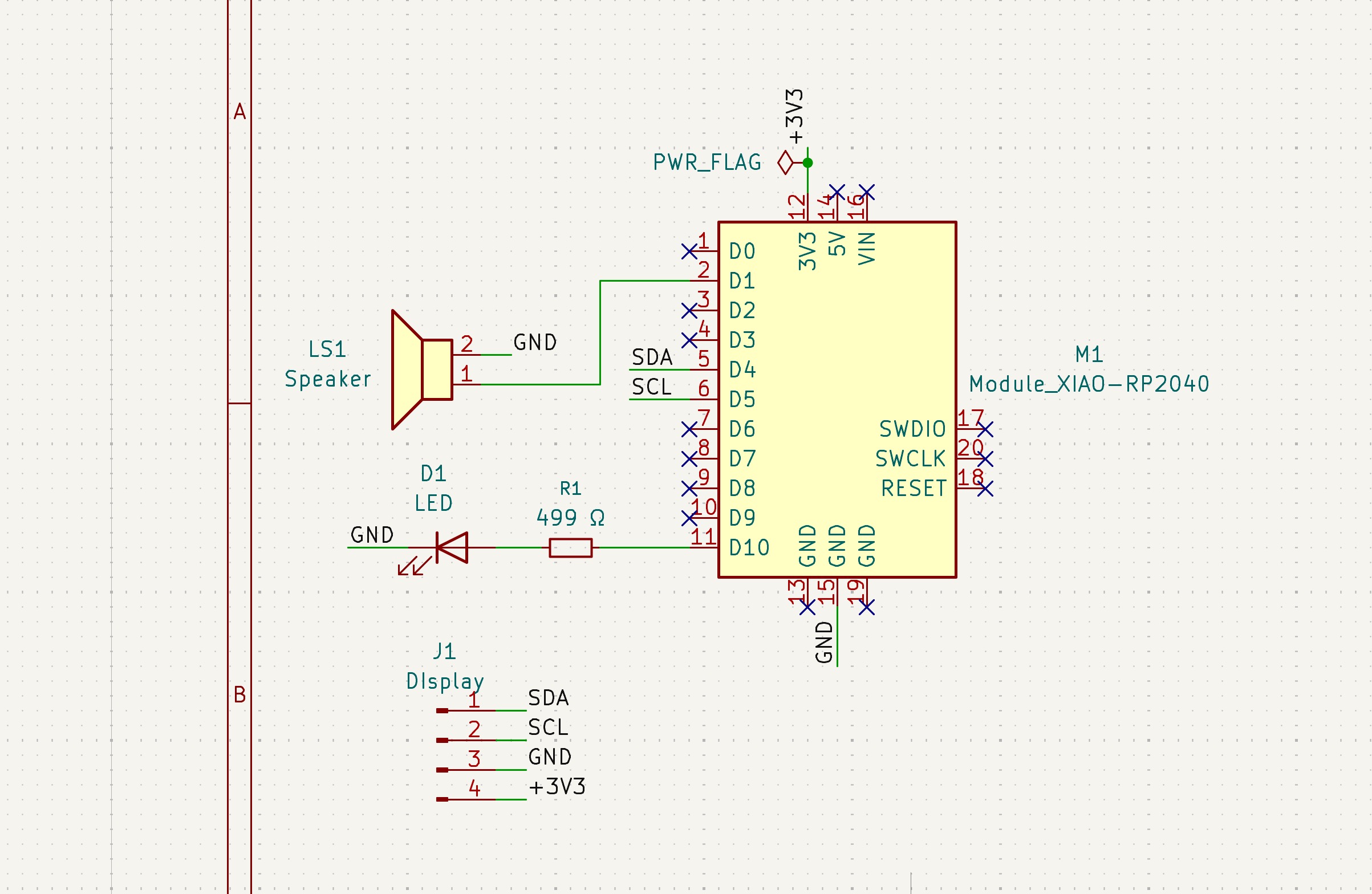
First, I added the XIAO RP2040 module (I won't be using the ESP32-S3 I plan to use in my final project since we don't really need its fancy camera module for this simple board.
Then, I added a the buzzer by simply connecting it to a pin and to GND, and an external LED for debugging.
The reason it only needs those two connections is that a piezo element (inside the buzzer) is essentially a capacitor. It's a crystal sandwiched between two electrodes, and it draws almost no continuous current.
The only current that flows is a tiny charge/discharge pulse each time the voltage switches, just enough to deflect the crystal. There's no coil, no electromagnet, nothing pulling steady current.
With a piezo you just apply a voltage difference across the two terminals and it moves. When you do that 2700 times a second, the crystal is vibrating, pushing air, making sound.
Finally, I added the display which is a white 0.96" OLED display panel with an I2C interface board. Here's the datasheet of a display very similar to the one I had available, in mine, the VCC and GND pins' positions were swapped.
I2C uses just two wires, SDA (data) and SCL (clock). The RP2040 drives the clock line and the display responds on the data line. Multiple devices can share the same two wires because each one has a unique address, 0x3C for this display.
Both lines need pull-up resistors to 3.3V, typically 4.7 kΩ, to pull the lines high when nothing is actively driving them. The I2C breakout board already has them built in, so no external ones needed.
On the XIAO RP2040, I used D4 and D5, which map to GPIO 6 and 7 internally and correspond to the first I2C bus. VCC to 3.3V, GND to GND, SDA to D4, SCL to D5.
How I2C controls the display?
While writing this, I wanted to dig deeper into how I2C makes the display show things?
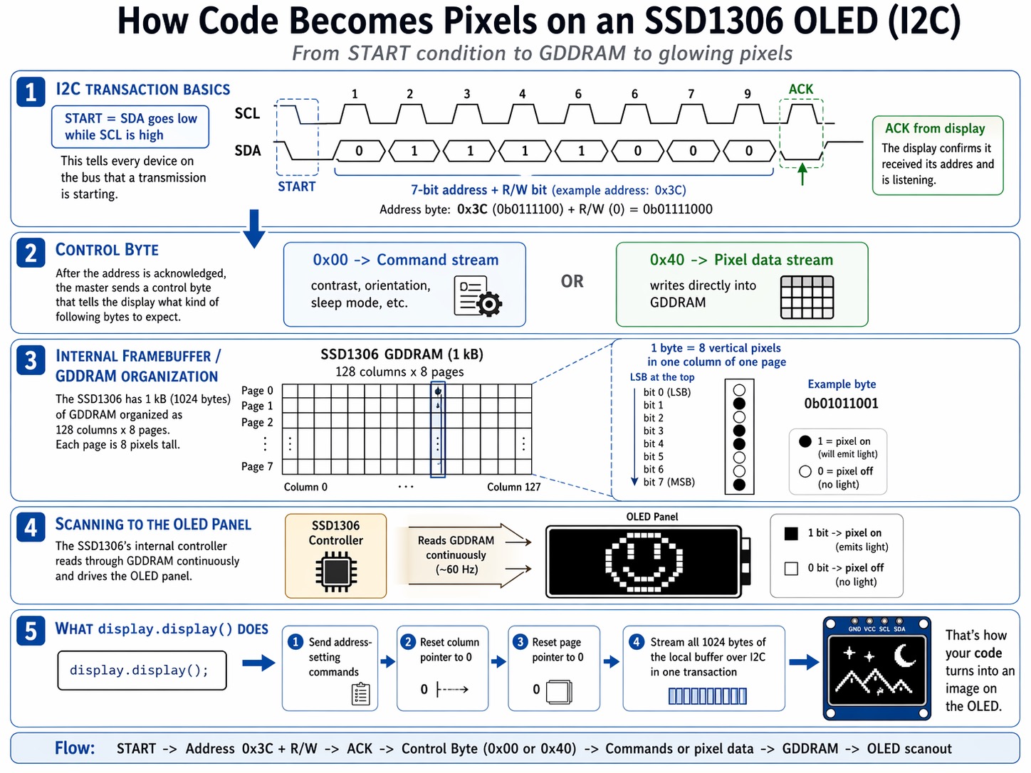
Every I2C transaction starts with the controller pulling SDA low while SCL is still high. That's the START condition, it signals to every device on the bus that a transmission is coming. Then 8 bits go out: the 7-bit address (0x3C) plus a read/write bit. The display pulls SDA low for one clock cycle to ACK, confirming it received its address and is listening.
The SSD1306 needs a control byte before any actual content. 0x00 means what follows is a command (contrast, orientation, sleep mode, etc.). 0x40 means what follows is pixel data going straight into GDDRAM, the display's internal 1 kB framebuffer.
That framebuffer is organized in pages. 128 columns, 8 pages, each page 8 pixels tall. Each byte you write sets 8 vertical pixels in one column of one page, with the LSB at the top.
The display's internal controller scans through GDDRAM continuously at around 60 Hz and drives each OLED element based on what it finds. A 1 bit means that pixel gets current and emits light. A 0 bit means it stays off.
When display.display() is called, the Adafruit library sends address-setting commands to reset the column and page pointers to 0, then streams all 1024 bytes of the local buffer over I2C in one transaction.
That's how your code translates into images on the OLED.
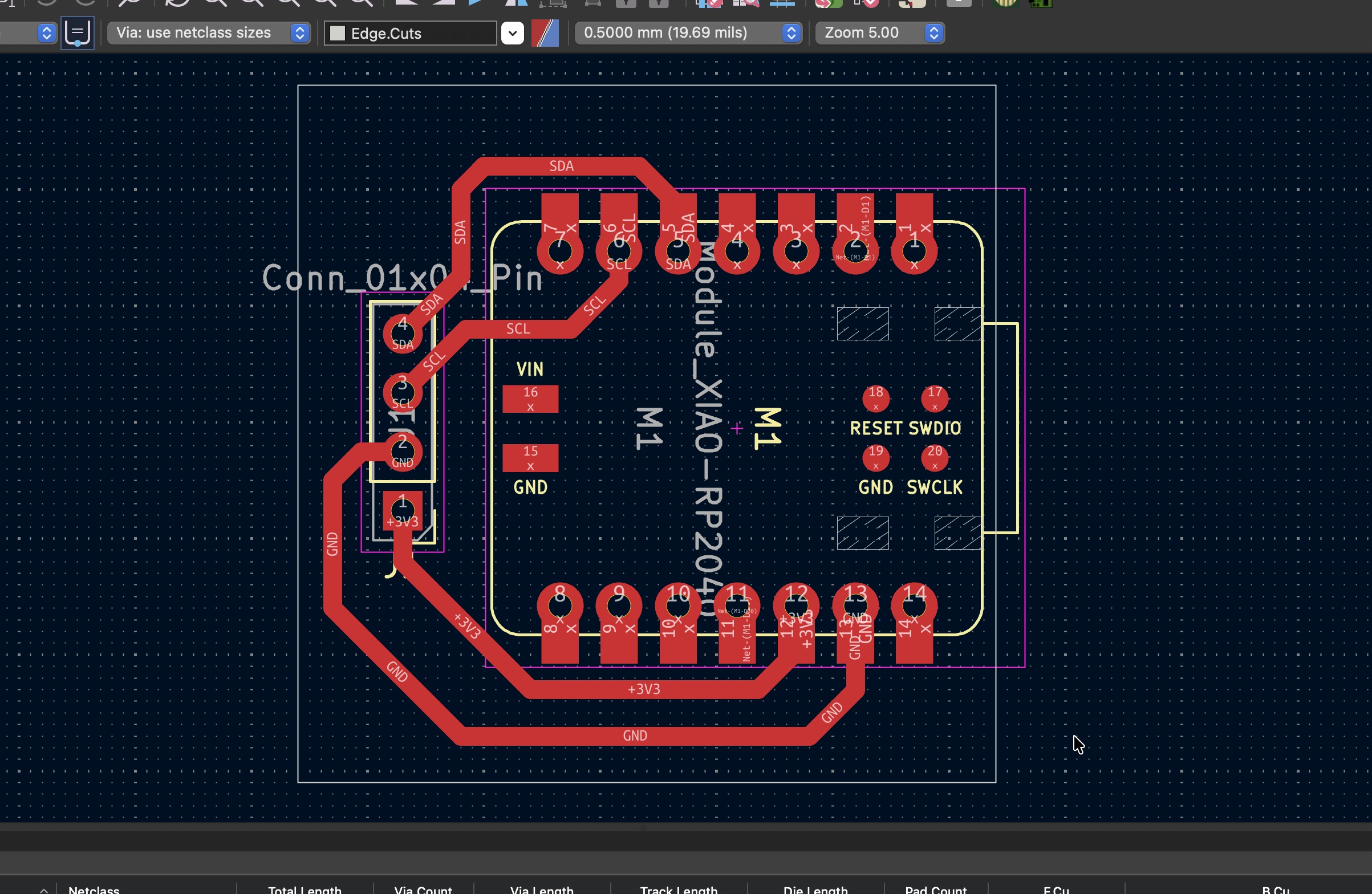
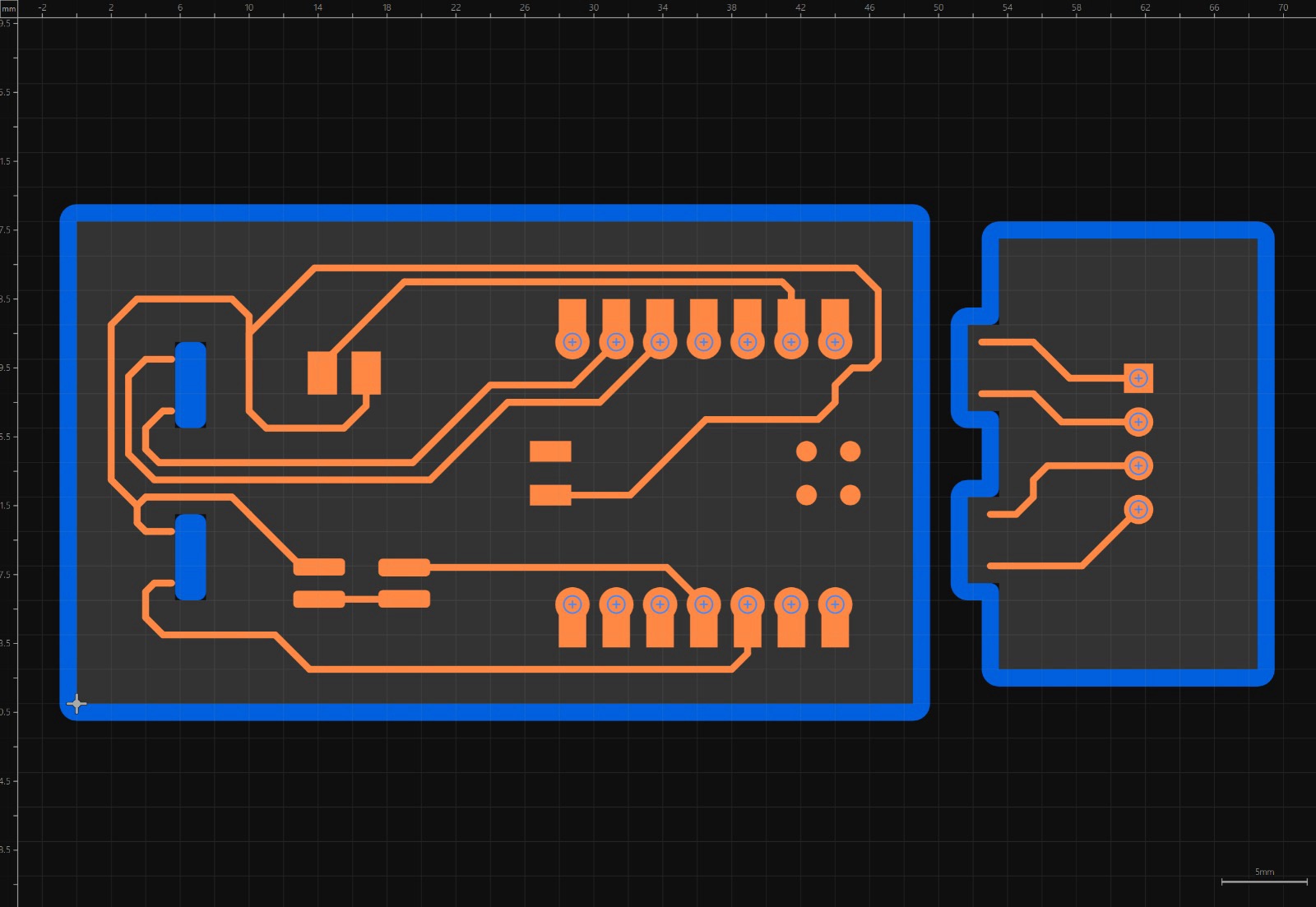
Then, it was time to route everything on my PCB editor.
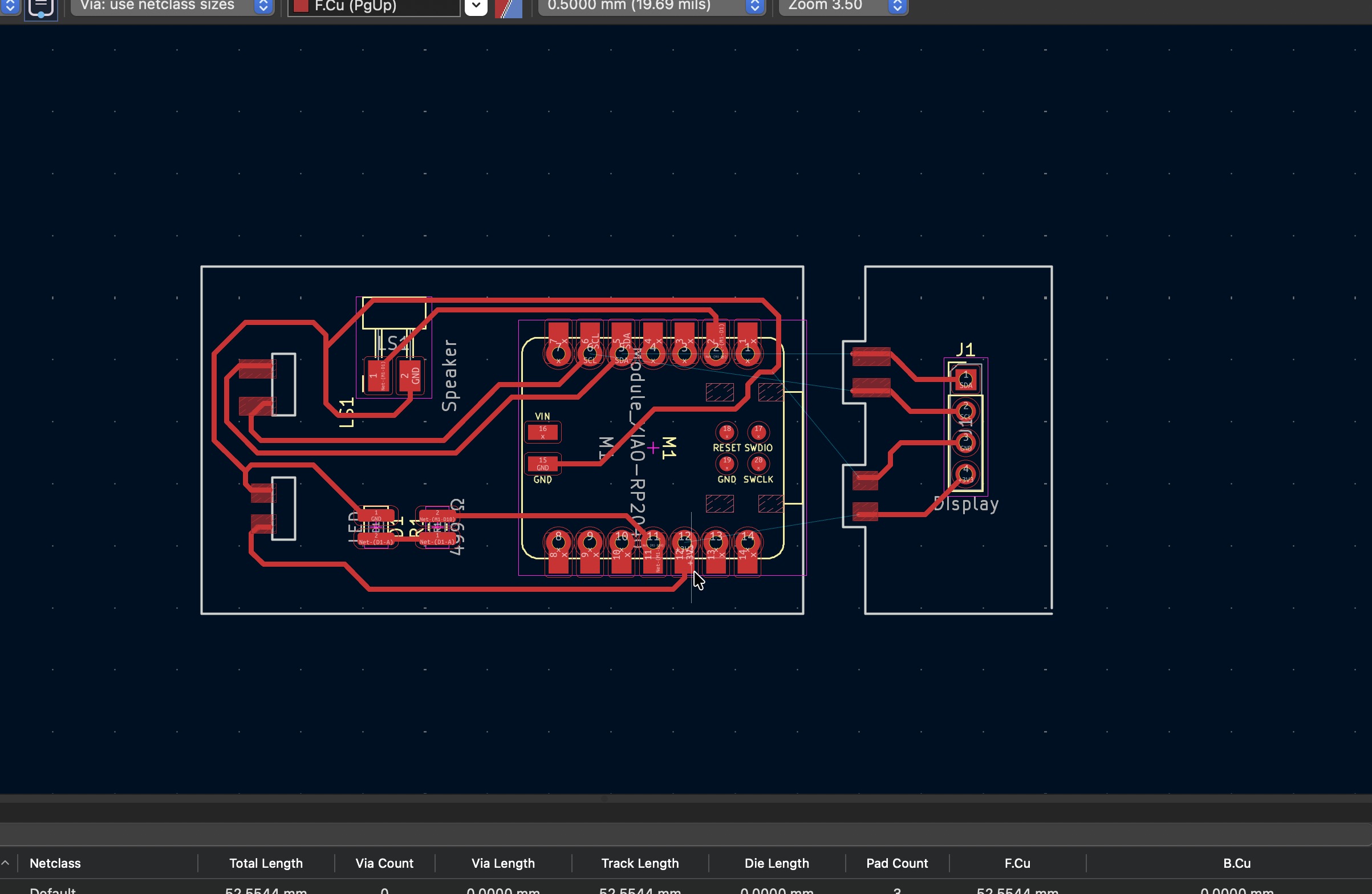
The way I routed it was very straightforward. As for connecting the display board to the main board, I used the marker lines I had in the exported DXF sketch to know the right position of the traces.
Then, I added pads to the end of each trace on both boards as you can see above.
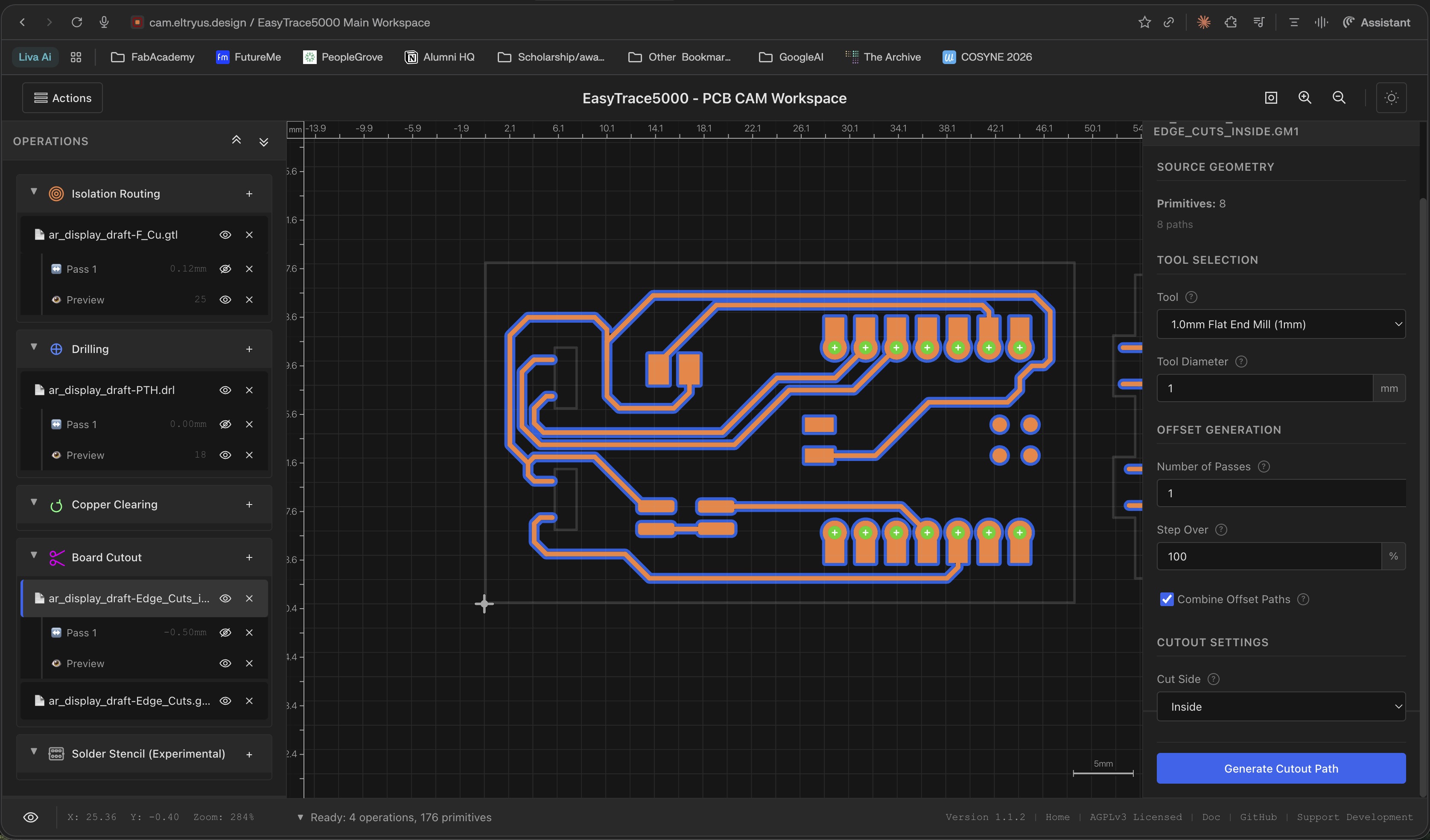
I exported the Gerber files and set up in EasyTrace5000 using the same settings as the previous weeks (Week 8: Electronics Production).
I needed to make the through-holes for the XIAO a bit larger to be compatible with our milling tool.
I also designed a simpler board afterwards due to some issues I explain below. The board was a simple RP2040 connected to a display.
Attempts at Milling and Soldering the 3D PCB + Simpler Version
I went ahead to start soldering, but there was something weird in EasyTrace5000 with the cuts for the board outline. However, I went ahead and milled anyway to check out how it would look like.
Reporting some issues to Ricardo to fix Easytrace5000 + Other Problems
If you notice, the hole for the press-fit was much larger than the joint from the display board, and it was an issue with how EasyTrace5000 processed the Gerber files and the slot I had messed up with how it processed the board outline.
This was how generally how the cut looked like (I don't have the exact screenshot). Essentially, it didn't process that the cut outside is supposed to be cut from the outside and for the slots, the mill should be inside.
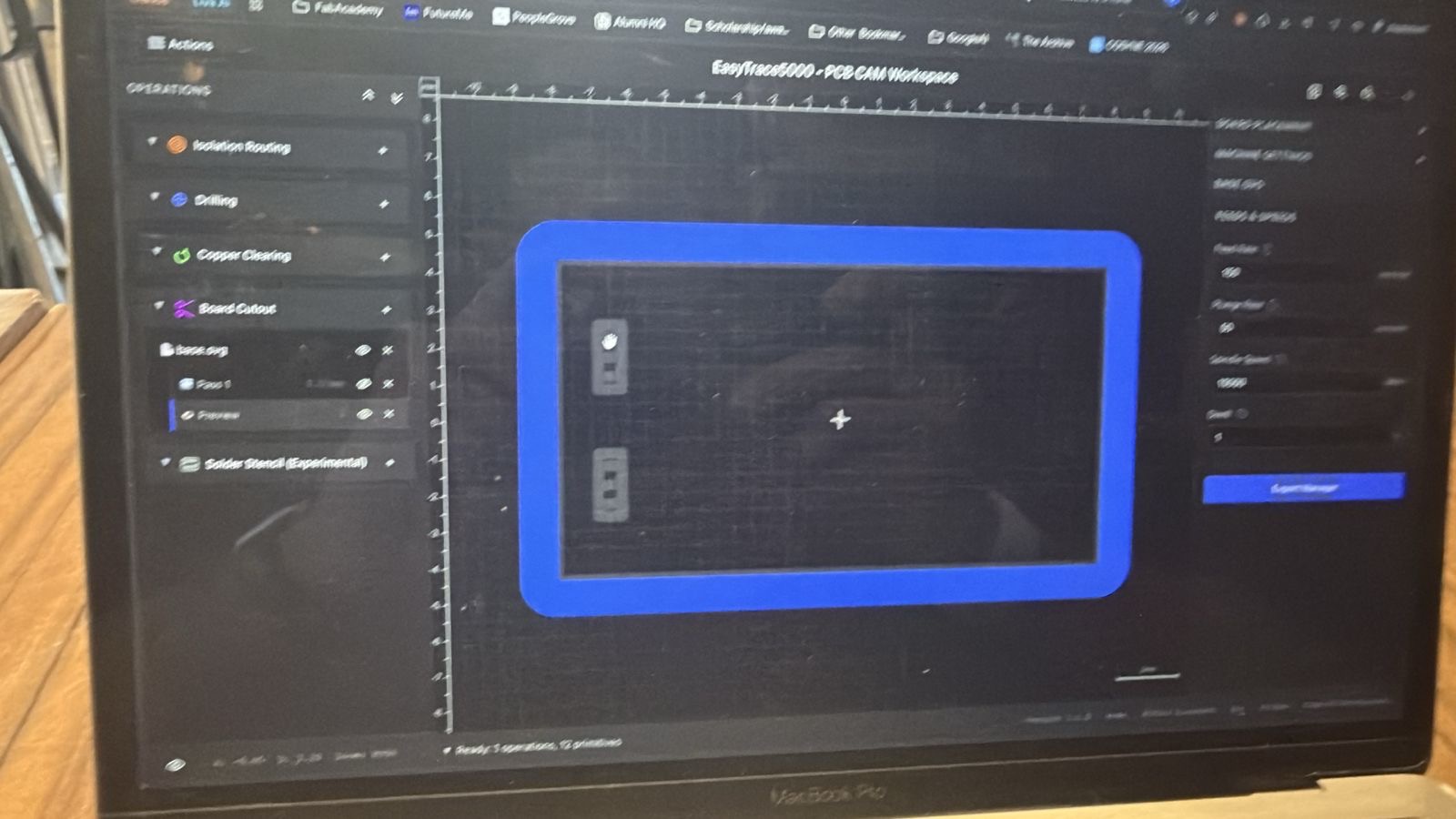
I reported the issue to Ricardo, and he fixed it. I milled the board a couple of times with different ways of importing for the outline EasyTrace5000, but none really worked and the outline mill ended up always cutting through the traces.
The root issue was that EasyTrace5000 wasn't ready for operations with two objects in the cutout. When you have a cutout with two shapes, like a board outline and a slot, it needs to know what's inside and what's outside each polygon to figure out which side of the line to cut on.
It didn't, so it just cut straight down the centerline of the shape boundary instead of offsetting correctly. The outer profile should be cut from outside the shape, and the inner slots from inside. It couldn't distinguish the two, so the toolpath was wrong from the start.
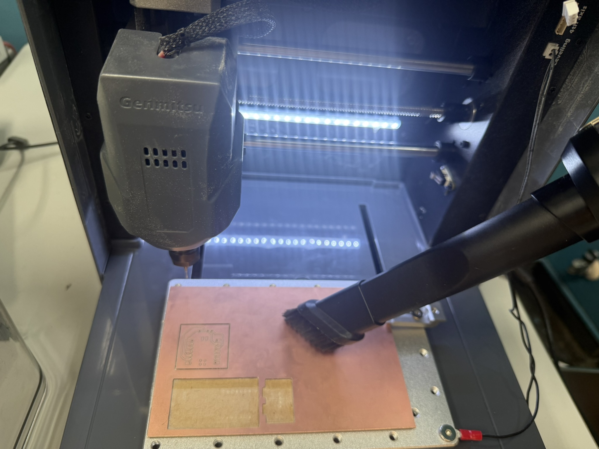
Meanwhile, I milled my other board, but not all the traces turned out great because of the worn out v-bit I used.
I was in a hurry then since I milled that board right before my plane to Saudi Arabia, and forgot to get an image of it later, but here is my personal set of soldering and electronics tools that were shipped to me in Saudi xD.
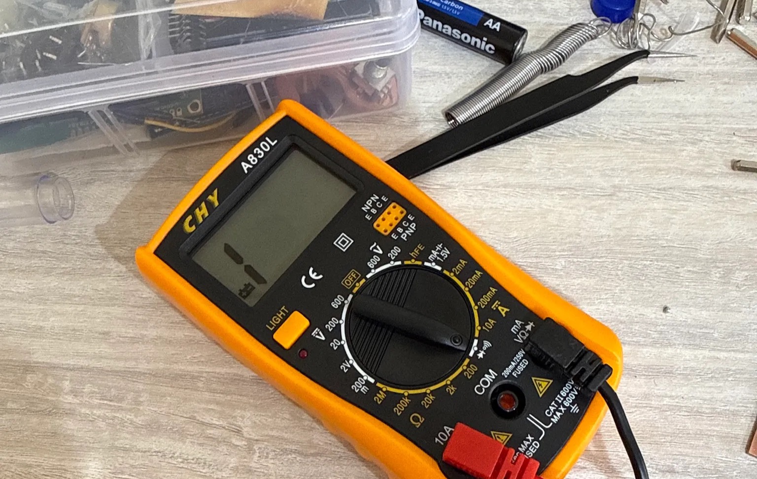
I didn't work on it when I was in Saudi since it was for family time, so I kept it till I was in Japan.
Successful Attempts
First part of the successful attempt was reaching Japan safely for the first time ever :D After struggling with jet lag, I met with Yuichi and got introduced to the lab and all the equipment, and got back to work.

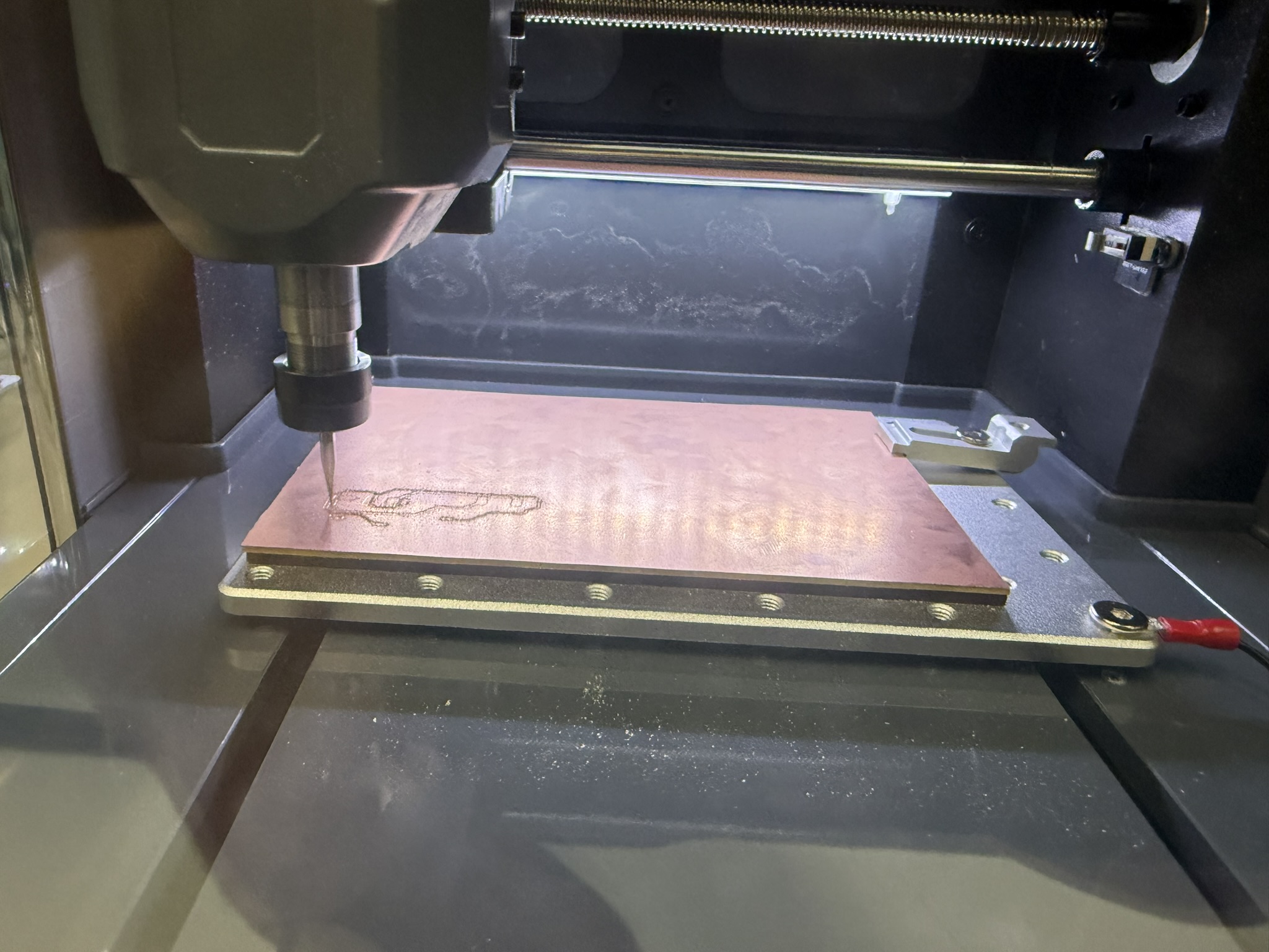
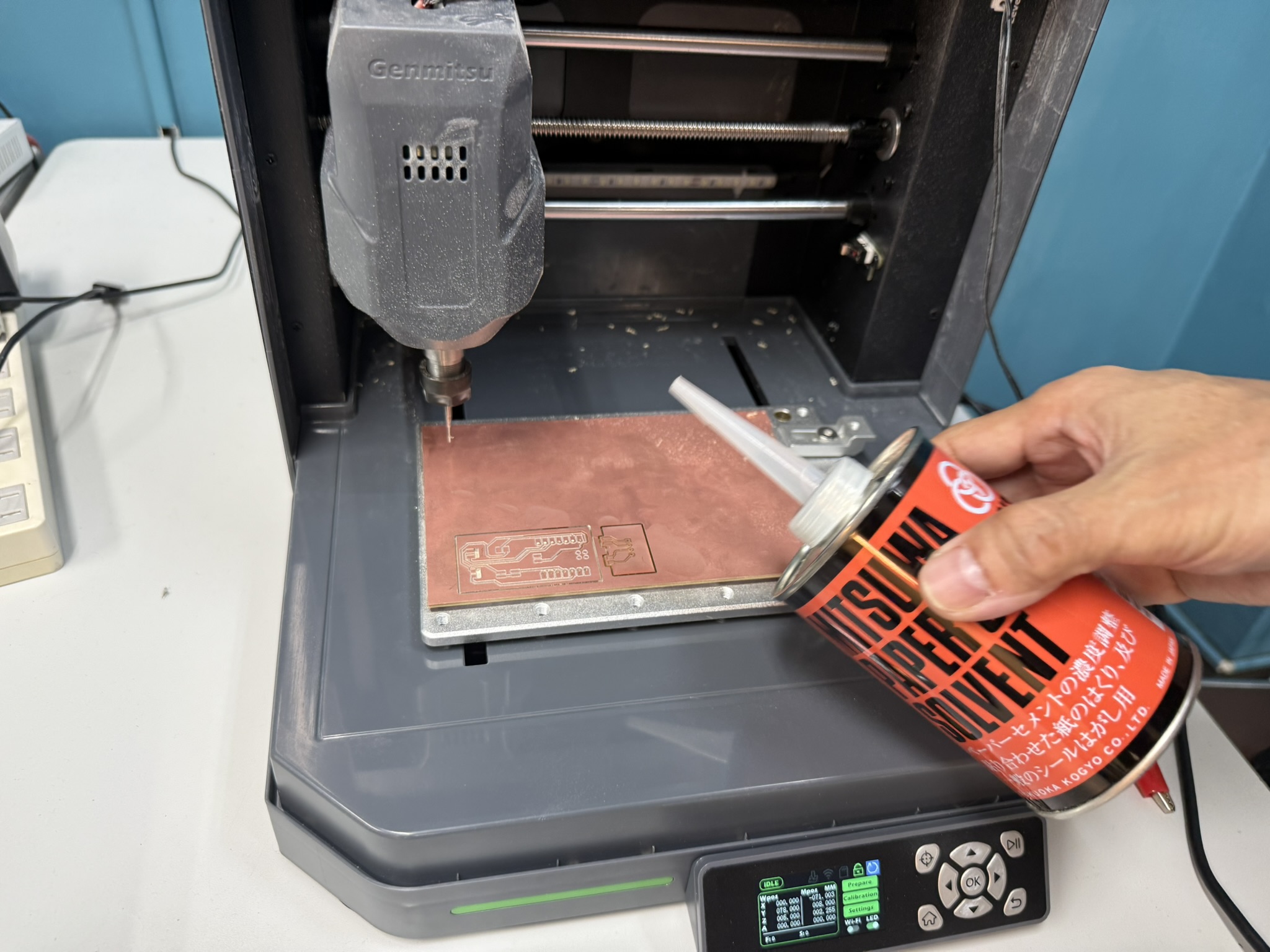
After Ricardo fixed EasyTrace5000, I needed to re-export the g-code and change the parameters for the v-bit since they have 30 degree v-bits here, so I needed to increase the depth of my tool from -0.04 mm to -0.05 mm.
Additionally, the drilling bit is the same as the board cutout mill: 0.7 mm flat-end mill.
I milled it the first time with the same setting as Portugal and it barely scratched the surface of the copper board, so I just re-milled it with the edited settings.
They also have a fancy door to the machine here xD
There wen't any big difference in controlling the Genmitsu Cubiko in Japan vs the machien we had in Portugal. It was all nearly identical when contorlling it through Candle.
The main difference was the thickness of the MDF under the copper board. In Japan, it was thinner, had the wood color, and was the same size as the copper board.
They also had a solvent which made removing the PCB from the MDF on the machine much easier.
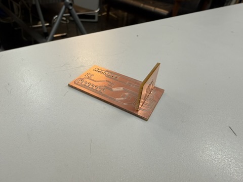
I milled both of the boards I designed.
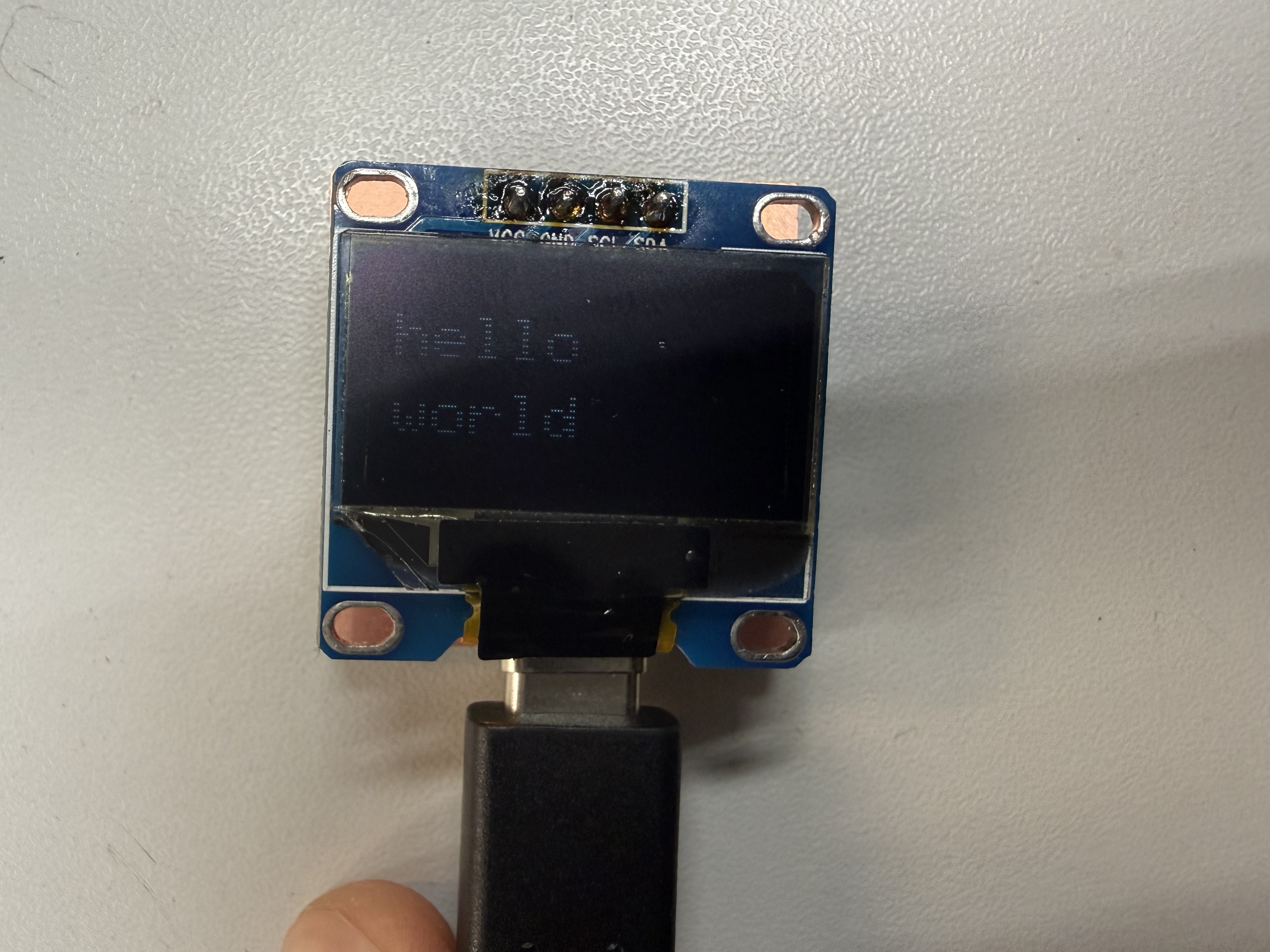
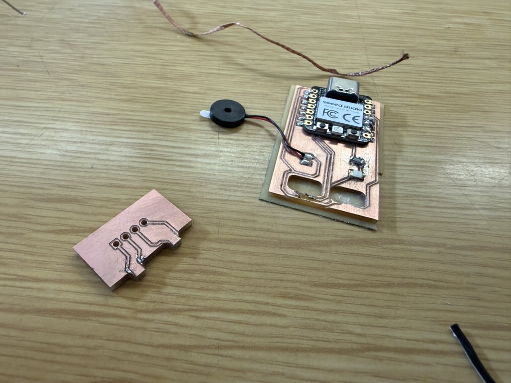
This time around the press-fitted board fit perfectly, and I started soldering.
I soldered everything properly, I confirmed it with a multimeter. Here is how the buzzer works.
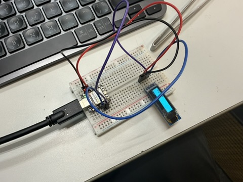
However, the display wasn't working properly, the traces were all connected, but the display would just suddenly flashing/jittering or be very dim, so I thought to try it on the other board.
Issues with the display
It worked, but the same issue persisted. I think the main issue with it was once in Benfica, the display fell and it broke off some parts of the glass on the bottom left corner, and I think that damaged some of its internals.
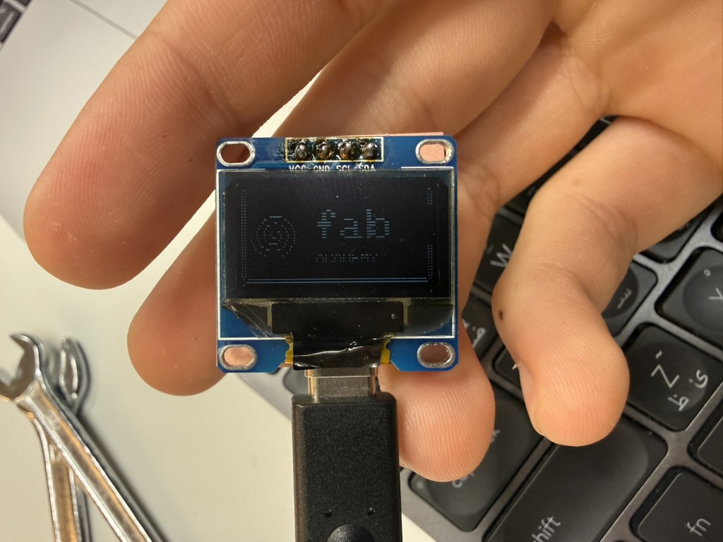
I wanted to make sure that it wasn't an issue with my rp2040 so I desoldered it, connected the display to another board through a breadboard, and connected another display to confirm this. I can confirm, the issue was the display :D
My display still worked, but it was very dim, so going forward, I will be using a new display and ordering a colored one for my final project.
The Code behind my PCB.
As in the past weeks, the code is written in C++ using Arduino on PlatformIO, targeting the XIAO RP2040.
I wrote two separate test sketches, one for the display and one for the buzzer.
The display code was more of a diagnostic tool, lol.
In setup(): it initializes I2C, detects the display address, runs a sequence of raw commands to verify the panel is physically working, then writes "TEST" to the screen. The loop() is intentionally empty, it runs once at boot and stops. Green LED means it worked, red means the display never responded.
Wire.setSDA(6) and Wire.setSCL(7) assign the I2C pins before Wire.begin() starts the bus. Wire.setClock(400000) bumps the speed to 400 kHz fast mode. These three lines all have to happen before anything tries to talk to the display.
Wire.setSDA(SDA_PIN);  // GPIO 6 = D4
Wire.setSCL(SCL_PIN);  // GPIO 7 = D5
Wire.begin();
Wire.setClock(400000);
The address detection tries 0x3C first, then 0x3D as a fallback. Most SSD1306 modules default to 0x3C, but some ship with the address pin pulled the other way. Checking both avoids a blank screen and a confusing silent failure.
If neither address responds, the built-in LED goes red and the program freezes.
if (display.begin(SSD1306_SWITCHCAPVCC, 0x3C)) {
    ok = true;
} else if (display.begin(SSD1306_SWITCHCAPVCC, 0x3D)) {
    ok = true;
}
if (!ok) { ledRed(); while (1) delay(1000); }
SSD1306_SWITCHCAPVCC tells the driver to generate the display's internal 7.5V from 3.3V using a charge pump built into the SSD1306 chip itself. No separate higher voltage supply needed.
The raw register commands bypass the display buffer entirely. 0xA5 forces every pixel on regardless of what's in the buffer, which is useful for confirming the display is physically working. 0xA7 inverts the whole image. These were diagnostic steps before trying to draw anything real.
display.ssd1306_command(0xA5);  // all pixels ON (test)
display.ssd1306_command(0xA7);  // invert display
display.ssd1306_command(0xA6);  // back to normal
display.clearDisplay() wipes the pixel buffer. Everything after it writes into that buffer. display.display() is what actually sends the buffer to the screen. Nothing appears until that one call.
display.clearDisplay();
display.setTextSize(2);
display.setTextColor(SSD1306_WHITE);
display.setCursor(10, 5);
display.println("TEST");
display.display();  // nothing shows until here
The built-in RGB LED is active low on this board, meaning you write HIGH to turn it off and LOW to turn it on. The ledOff() helper sets all three pins HIGH first, then individual color functions pull just one pin LOW.
Buzzer
I explained how the buzzer works electronically. Here's the code explanation. The code file for this also contains blinking an LED, but I didn't solder it.
The code generates the square wave using analogWrite. Setting the duty cycle to 128 out of 255 gives exactly 50%, which is the loudest a square wave gets since the crystal is spending equal time deflecting both ways. To clarify, it doesn't go in the negative direction xD
void playTone(int pin, int frequency, int durationMs) {
  analogWriteFreq(frequency);
  analogWriteRange(255);
  analogWrite(pin, 128);  // 50% duty = maximum volume
  delay(durationMs);
  analogWrite(pin, 0);    // silence
}
Since every piezo is slightly different, the code runs a sweep from 500 Hz to 5 kHz at boot, stepping 250 Hz at a time. You listen for the loudest point and update RESONANT_HZ in the code before re-flashing. It's a manual calibration step but it only takes a few seconds.
The alarm pattern alternates between RESONANT_HZ and RESONANT_HZ * 3/4. That ratio drops the second tone by a musical fourth, which is the classic two-tone alarm sound. The RP2040 handles the timing and the piezo plays the sounds.
void playAlarm() {
  for (int i = 0; i < 4; i++) {
    playTone(BUZZER_PIN, RESONANT_HZ,         150);
    delay(40);
    playTone(BUZZER_PIN, RESONANT_HZ * 3 / 4, 150);
    delay(40);
  }
}
Original Design and Code Files
This week's checklist
- Linked to the group assignment page.
- Documented how you determined power consumption of an output device with your group.
- Documented what you learned from interfacing output device(s) to microcontroller and controlling the device(s).
- Linked to the board you made in a previous assignment or documented your design and fabrication process if you made a new board.
- Explained how your code works.
- Explained any problems you encountered and how you fixed them.
- Included original source code and any new design files.
- Included a 'hero shot' of your board.