
Week 09
Week 09: Input Devices
I focused on input devices by redesigning the neuron PCB as a software LIF board, then milling, soldering, and testing it as an input-focused electronics step.
This week I finally brought to life the neuron PCB idea I had, and started more seriously thinking and working on my final project as I gathered a solid base in electronics design (got to get Neil's thoughts on it too, during week 10's session).

Jump to this week's checklist
Group Assignment: Probing Analog and Digital Signals from Input Devices
The group assignment this week was about probing the signals coming from an input device with a multimeter and an oscilloscope. The full group write-up is linked above.
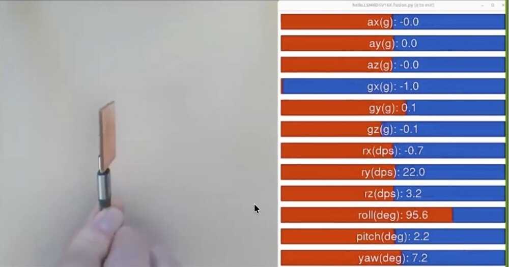
We probed the EC11 rotary encoder, which is also the input device I used for my individual assignment. So this was less of a "pick something random and probe it" exercise and more of a chance to understand what my own board was reading.
A rotary encoder is interesting because it does not give you an analog voltage the way a potentiometer does.
It gives you two digital square waves on channels A and B, ninety degrees out of phase. Which channel transitions first tells you the direction of rotation. The frequency of the pulses tells you speed. The fancy name for this is quadrature encoding.
The first thing we did was measure the static voltages on the encoder pins with the multimeter. With the internal pull-ups enabled on the XIAO, both channels sat at 3.3V at rest, and dropped to about 0V when a detent fired. So already from the multimeter alone, we could see that the pull-ups were doing their job and the signals were clean rail-to-rail.
But the multimeter only tells you what the voltage is right now. It cannot show you the timing relationship between two channels, which is the entire point of a rotary encoder.
That is what the oscilloscope was for. We hooked channel 1 to encoder A and channel 2 to encoder B and turned the knob.

Turning clockwise, channel B transitioned before channel A. Turning counterclockwise, channel A transitioned first. That phase flip is the entire mechanism.
There is no special "direction" line. The direction is encoded in which signal moves first.
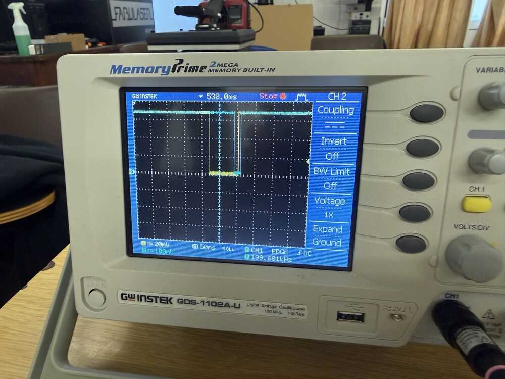
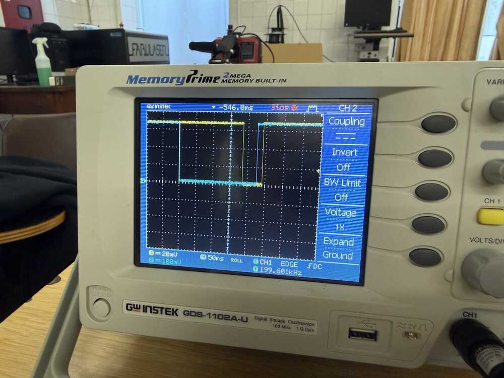
Pulse width also tracked rotation speed. Slow turns gave wide pulses, fast turns gave narrow ones bunched together.
The speed of rotation maps directly to pulse frequency, which is something the code in our group assignment doesn't use (it just counts clicks), but you could extract it if you wanted to.
We completed the group assignment after I milled my board in my individual assignment, so it was a good way to check the rotary encoder worked :D
Learnings
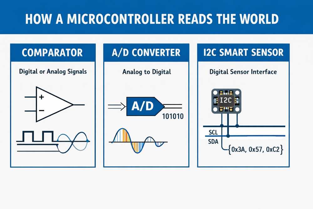
This session was basically a massive tour of every sensor. Neil mentioned that if you pick the right sensing principle up front, you can let the hardware do the heavy lifting and save yourself from writing a ton of complicated code.
Three broad categories for how a chip sees the outside world: a comparator (is the voltage above or below a threshold? yes/no), an A/D converter (gives you an actual number from that voltage), and an I2C smart sensor (does the conversion on its own little chip and just hands you a clean digital reading over two wires).
Pretty much everything else in the session was one of these three ideas wearing different physical clothes.
The simplest possible inputs
Simplest input: a push button. Next up is the potentiometer, just a variable resistor giving you a voltage proportional to its position.
Worth comparing this to the rotary encoder I used this week since they both answer "how far has something turned" but with completely different physics.
Potentiometer gives you an absolute analog voltage. Encoder gives you incremental digital pulses. That difference completely changes how your firmware ends up looking.
One thing I hadn't thought about: Neil mentioned potentiometers are useful as little tuning knobs for motor current. Basically a debugging tool you solder onto a board so you can dial in a parameter live.

Magnetic field sensors and rotary encoders
Hall effect sensor: give it power and ground, and it outputs a voltage proportional to the magnetic field strength. It can pick up the Earth's magnetic field. A few-cent part that does that! The code is literally just analogRead.

A vector magnetometer does the same thing but on three axes. Single Hall sensor is good for stuff like detecting a lid closing. Vector magnetometer tells you which way you're pointing in space, which is how a car gear shifter knows what position it's in.

Magnetic rotary encoders are built on the same idea. Magnet glued to the shaft, sensor underneath. The thing I hadn't realized: the magnet inside an encoder points sideways into the sensor, not up out of the top.
The sensor reads the rotating field and reconstructs the angle. Basic ones give you about 10 bits of resolution, and there are 21-bit parts with way more onboard processing for closed-loop motor control. You can map exactly how a stepper is moving down to the microstepping level, which is the entry point to closed-loop control.
Most of these smart sensors talk over I2C, so you need pull-up resistors on SCL and SDA. Networking week will go deeper into why, but the short version is that I2C lines need to be pulled high for the open-drain signaling to work.
Step response, Neil's favorite Input
This one blew my mind a little. It's called Step Response and it's Neil's favourite input. It can work with just 1 pin but more complex versions exist.
A piece of conductive tape. And from that you can measure touch, multitouch, force, bending, distance from a hand, humidity, acceleration, and even molecular properties of liquids. All from the same basic element.
Here's why it works: any electrode is a tiny capacitor coupled to its surroundings. You put a voltage step on the electrode, and the way the voltage rises or falls depends on that capacitance.
When something nearby shifts the electric field (a finger, water, a hand at a distance), the capacitance changes. So you're reading the time response of an RC circuit and figuring out what's near the electrode from how the response shifts.
The simplest version is self-capacitance. Drive a step into the electrode, measure the curve. Some processors have a peripheral called QTouch built in for exactly this, and there are libraries to do it directly on the XIAO. You can also build it with a regular resistor and any pin.
Or even without an external resistor, because every pin on a chip like the RP2040 has an internal pull-up you can switch in and out from software. Toggle the pin to charge the capacitor, flip it to an input and watch it discharge. The curve comes entirely from internal components.
The timing needs to be at the microsecond level, which is too fast for a regular Arduino loop. The RP2040 in the XIAO has PIO, which is essentially a set of tiny programmable processors sitting next to the main core.
Each PIO has a couple of state machines you can program at a very low level. Perfect for this kind of timing. For environmental noise, you average many readings together, which knocks down the electrical hum from the room.
Then there's mutual capacitance, which is way more robust. Instead of relying on the room's ground as a reference, you have a transmit electrode and a receive electrode.
Signal goes from transmitter through whatever is in between (your hand, foam, a flex sensor) and back to the receiver. Doesn't matter what room you're in, the measurement stays consistent.
You can put electrodes on opposite sides of a wedge of material and get angle from how much they overlap. Run a transmit and receive trace alongside a flexible material to read bending. Hide an electrode inside a container and use it as a pressure pad.

If you push to much higher frequencies, you cross from sensing geometry into something closer to dielectric spectroscopy, reading molecular properties of whatever is touching the electrode.
Here's a cool example from this week's website about how it works. It is pretty cool, and I think I will be using it as a capacitive touch for the glasses' temple to control the glasses.
Temperature, light, and the Wheatstone bridge
RTDs (Resistance Temperature Detector) change resistance with temperature. The problem is the change is small, so a simple voltage divider won't show it cleanly. Enter the Wheatstone bridge: three resistors that roughly match the RTD, arranged so that when everything is balanced the output voltage sits at exactly zero.
Now any tiny shift in the RTD's resistance shows up as a small voltage on top of zero, instead of getting lost inside a much larger DC offset.
This idea applies way beyond temperature. Whenever you need to measure small changes in a small signal, bias everything around zero so you don't burn all your A/D resolution on the offset.
That kinda connects with my EEG glasses, where the brain signals are microvolts sitting on top of a much larger noise floor. Turns out bridge circuits and that same balancing logic are what front-end EEG amplifiers use under the hood.
Phototransistors let light vary the current through them, and you read the voltage across a load resistor.

The cool trick with phototransistors is synchronous detection. Say I want to know if a finger is hovering over a sensor.
Measuring absolute light is useless because it depends on the room. Instead, I put an LED next to the phototransistor and switch it on and off rapidly. Subtract the off-readings from the on-readings, and what's left is just the light from my own LED reflecting off the finger. Room background cancels out completely.
This is basically how every reflective optical sensor works.
For actual color sensing, parts like the Vishay VEML6040 or Broadcom APDS-9960 wrap a color filter array and an A/D into one I2C package. The datasheet tells you which registers hold the red, green, blue, and clear channels, and you just read them over I2C.
Motion, distance, and time of flight
PIR (Passive Infrared) sensors still exist but they're basically obsolete at this point. For a few dollars you get a Doppler radar instead.
It puts out a microwave signal and mixes the outgoing wave with the reflected one. Only measures the Doppler shift though, so it tells you whether something is moving and how fast, not how far away it is.
For actual distance, optical time of flight (lidar). Light travels about a foot in a nanosecond, so measuring short distances means timing at the picosecond level.
The VL53L0X handles all of that internally and gives you a clean distance reading over I2C. ST also makes a multizone version (VL53L5CX) that returns an 8x8 grid of distances, so you can tell if an object is partially in the field of view or moving across it.
The old ultrasonic sonar modules you see in Arduino tutorials are basically obsolete by comparison.
Time and position
Real time clock modules like the PCF8523 keep time even when the board is off, thanks to a tiny coin cell.
GPS modules like the NEO-6 are super cheap now. Wire one to an antenna, wait for it to find satellites on the first boot, and you get position.
Bonus: you also get extremely accurate time, because every GPS satellite has an atomic clock onboard. That timing is actually what makes the whole position fix work, which I hadn't really thought about before.
Accelerometers and IMUs
3-axis accelerometer: XYZ acceleration. 6-axis: add rotation rate on three axes (gyroscope). 9-axis: add magnetic field on three axes too. With acceleration and rotation you can fuse them to figure out which way the device is pointing in space. That's how every phone tracks its orientation. You actually want the 9-axis version because the magnetometer gives the fusion algorithm an absolute reference, stopping the orientation estimate from drifting over time.
Fun fact Neil mentioned: you can mount an accelerometer on a CNC machine to read the high-frequency vibration of the cutter. You can even pull audio out of the data. Cool overlap with milling week.
Sound and vibration
Sound used to require a stack of microphones, op-amps, and analog filters. Now a digital MEMS microphone like the ICS-43434 talks I2S (same idea as I2C but designed for streaming audio samples) and handles all of that. With two microphones you can compute the angle a sound is coming from by comparing arrival times. That's the basis of every smart-speaker beam former.
Vibration: piezo. Force: strain gauge. The strain gauge uses R = rho * (length / area) and the fact that stretching a wire changes its length and cross-section. A serpentine strain gauge bonded to a metal element is what's inside a load cell. That's how trucks get weighed at highway scales, which I had no idea about.
For heart rate, tiny modules bounce LED light off your finger and watch how the reflected color shifts as blood flows through. Same principle as a hospital pulse oximeter.
Cameras and the edge ML option
The XIAO Sense has a camera onboard and can stream video over WiFi to a webpage in your browser. From there you do motion detection, color inversion, and other image processing in JavaScript using WebRTC.
Way friendlier than learning a full embedded vision stack. For heavier vision work there's the Grove Vision AI module, and the Pi Zero 2W is genuinely powerful for the price.
Neil's caveat though: jumping straight to a Linux board is usually overkill. Always try to find the lowest-level part that does the job before reaching for one.
Brief Insights from the Machine Building Recitation
The following link has "open designs of fab lab machines that can be made in a fab lab."
When you design a machine, start from what you actually need it to do (the workpiece, the forces, the precision) rather than copying someone else's frame and hoping it fits. Think from first principles.
The portal collects work from a list of people who've been building open machines for years. There are a lot of different machines covered during the session. You could check them out here.
The Open Lab Starter Kit and Simple Machine Kit are modular, well-documented, and you can get a working motion system in a weekend. Once you have one running, you have way better intuition for what to change when you design your own.
Modular Things is the software-side version of this, where the Editor lets you script machine moves without writing firmware.
This note will come in handy for my machine building week.
Neil's feedback on my final project's EEG input
This feedback actually came during next week's session, but it's very relevant to this week.
I asked Neil about using an EEG as an input device for my final project. His advice was pretty direct: pick an AVR (specifically an ATtiny) that has a differential ADC with a built-in programmable gain amplifier. That way you connect the electrodes straight to two ADC pins, set it to differential mode, crank the gain up, and the chip handles the voltage difference measurement and amplification internally. No external op-amp needed.
He also mentioned slowing down the ADC clock rate for cleaner readings, since you're trying to resolve microvolts. And there's an ADC Noise Reduction sleep mode where you shut down the CPU, timers, and everything else on the chip except the ADC. That kills all the internal digital switching noise that would otherwise contaminate the measurement. Same approach would work for ECG or EKG.
His example code uses pins and registers directly rather than Arduino abstractions, since you need that level of control to configure differential mode, gain, and clock prescaler. You'd need to import the right MCU core package (like megaTinyCore) into Arduino IDE or PlatformIO to get access to those registers.
Not every ATtiny has this though. The 0-series and 1-series parts (like the ATtiny402 or ATtiny412) only have a single-ended ADC with no differential mode or gain. The tinyAVR 2-series chips (like the ATtiny1627 or ATtiny3227) are the ones to look at since they have a 12-bit differential ADC with up to 16x gain. Still need to dig into the datasheets and figure out which specific part makes sense for the signal levels I'm dealing with.
Designing the "Altered" Software LIF Neuron PCB
I am carrying on the work from week 6 where I designed a PCB board that mimics how a neuron works by "translating" the math of the LIF neuron model into different electrical components. Check out the full explanation of that in the Week 06 LIF Neuron section.
However, as I learnt more about the capabilities of our machine, the components we have available at the lab, and my current soldering/milling capabilities, I decided to create a simpler version of this.
Instead of simulating the math in the hardware, I decided to do the math on a XIAO-ESP32-S3. In hindsight, I would've used a cheaper MCU since I didn't really need all its features and power.
A rotary encoder rotation would translate to input voltage into the neuron. It isn't really inputting any additional voltage from somewhere magical I am just simulating that in software.
Then, a bunch of LEDs will simulate the neuron's membrane and when the neuron fires to transmit signals to other neurons.
I will get into a deeper explanation of each aspect of my board later in this section.
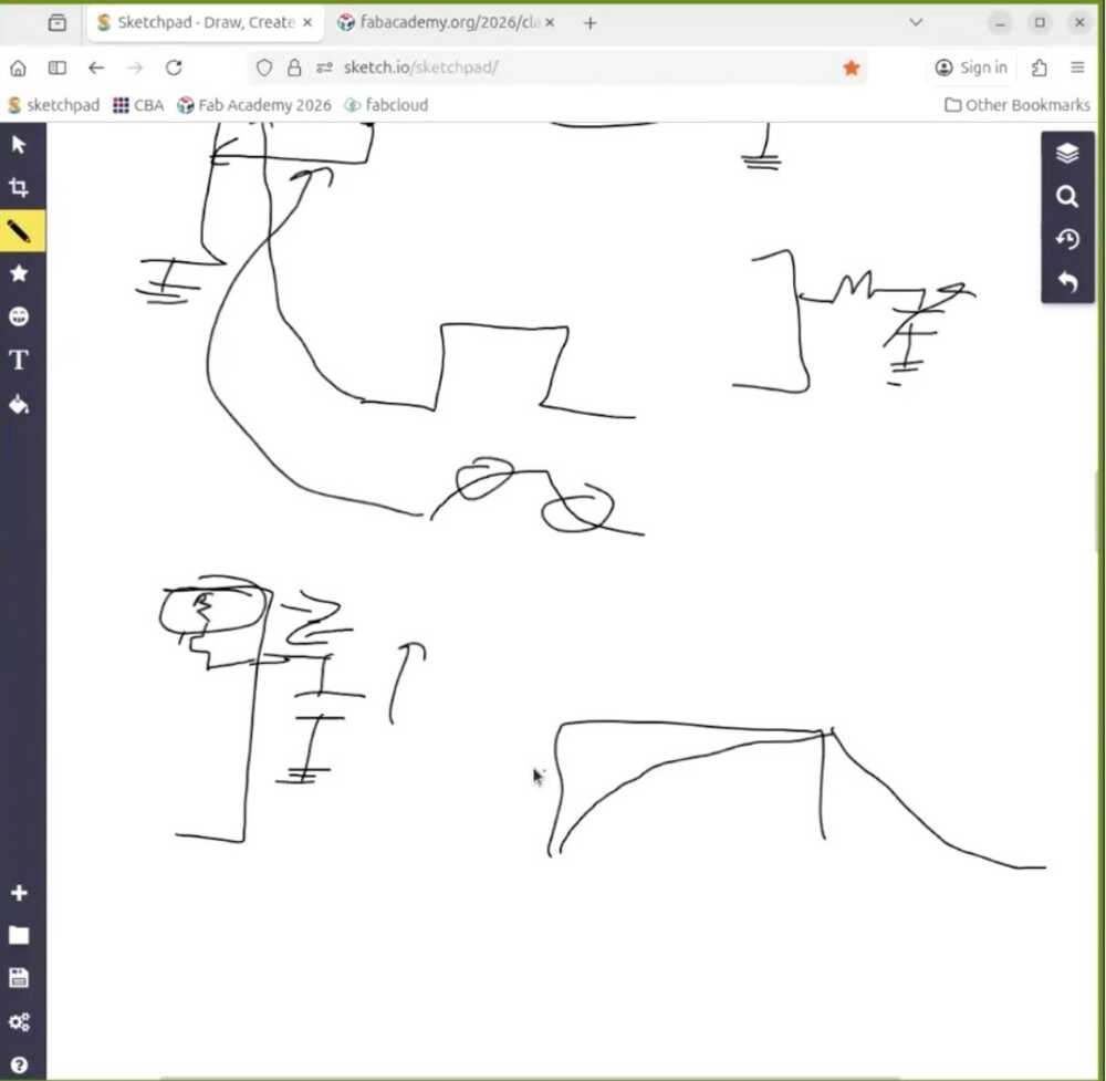
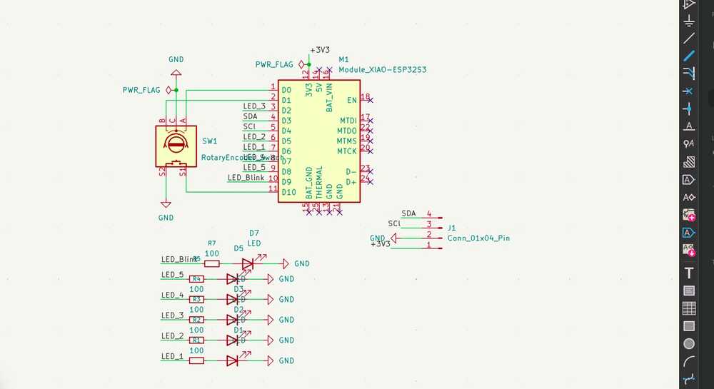
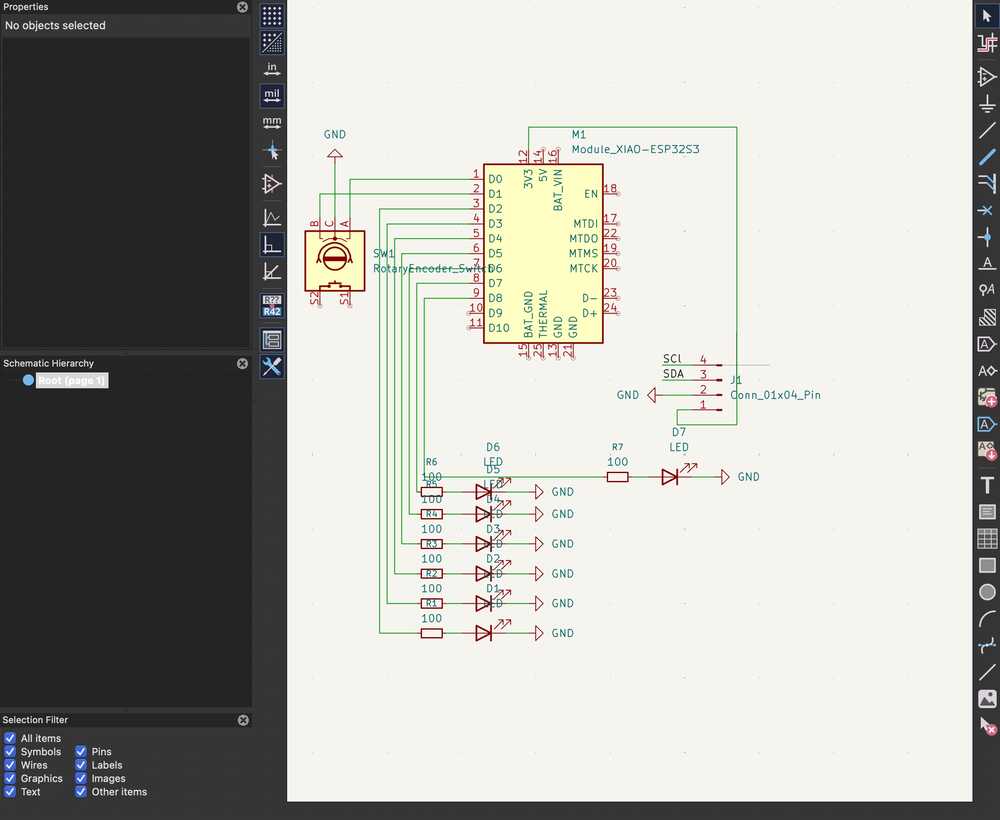
Creating the Board's Schematic
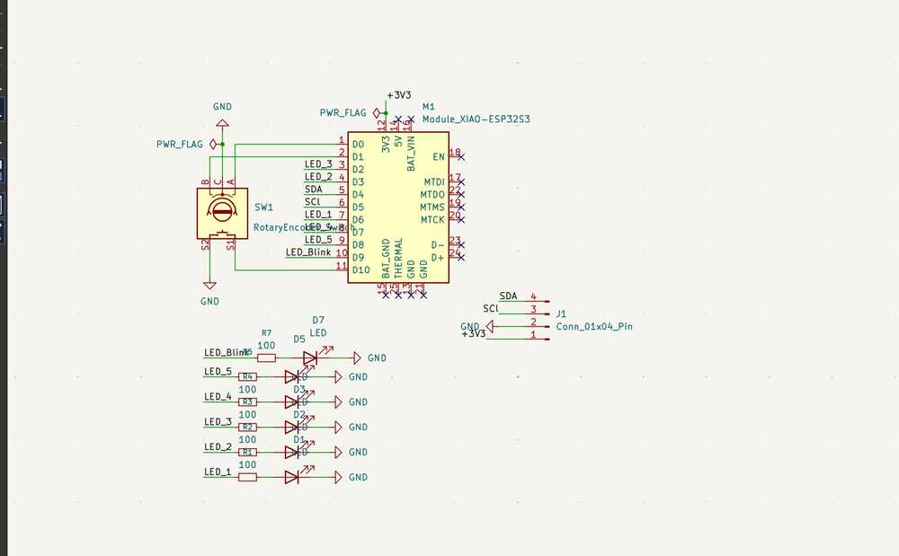
The schematic is pretty straightforward. I placed the XIAO ESP32-S3 module in the center, then added the EC11 rotary encoder with its A and B channels going to D0 and D1, and the common pin to ground.
For the LEDs, each one connects to a GPIO pin through a 100 ohm (in my milled board I used a 500 ohm resistor instead and it works since i am just using a red and green LEDs) resistor. I also added a 4-pin connector (J1) breaking out SDA, SCL, 3V3, and GND in case I wanted to hook up an I2C device later (a screen probably).
One thing to watch out for: D6 and D7 on the XIAO ESP32-S3 are the default UART0 TX/RX pins (GPIO43 and GPIO44). If you want to use them as regular GPIO, you need to call Serial0.end() in your firmware to release them.
USB serial still works fine since it runs on a separate USB peripheral.
I ran the ERC, placed the PWR_FLAG symbols, and made sure no-connect flags were on unused pins. Then assigned footprints to everything (through-hole for the encoder and connector, SMD 0805 for the resistors and LEDs) and updated the PCB from the schematic.
What I realized later when I milled the board is that my SDA and SCl were shifted up 1 pin. They should've been connect to D4 and D5 instead of D3 and D4. This was how it looked originally, but thankfully the display wasn't an important part of this week's build so I didn't have to re-mill the board.
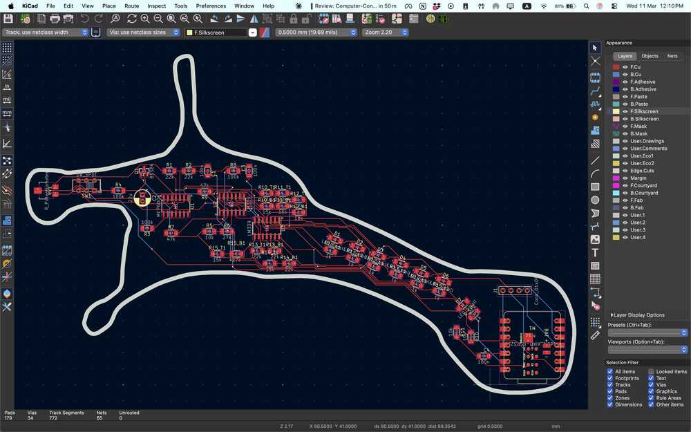
Creating the PCB
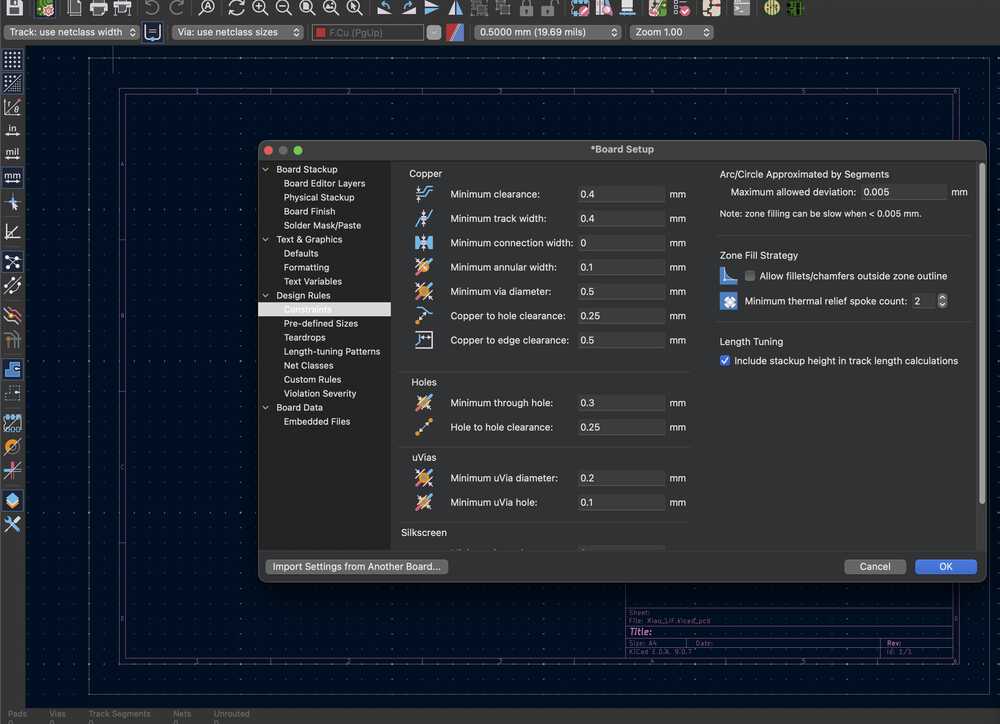
The first step was to set all the design rules and contraints. They were the same as last week and I used 0.4 mm traces.
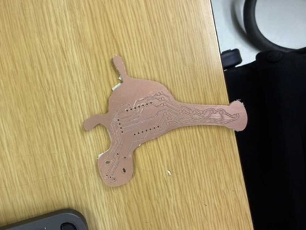
Before heading to import the schematic to the pcb, I edited the design of the neuron from that week to ensure I can fit everything on the board. I did that on Inkscape :D

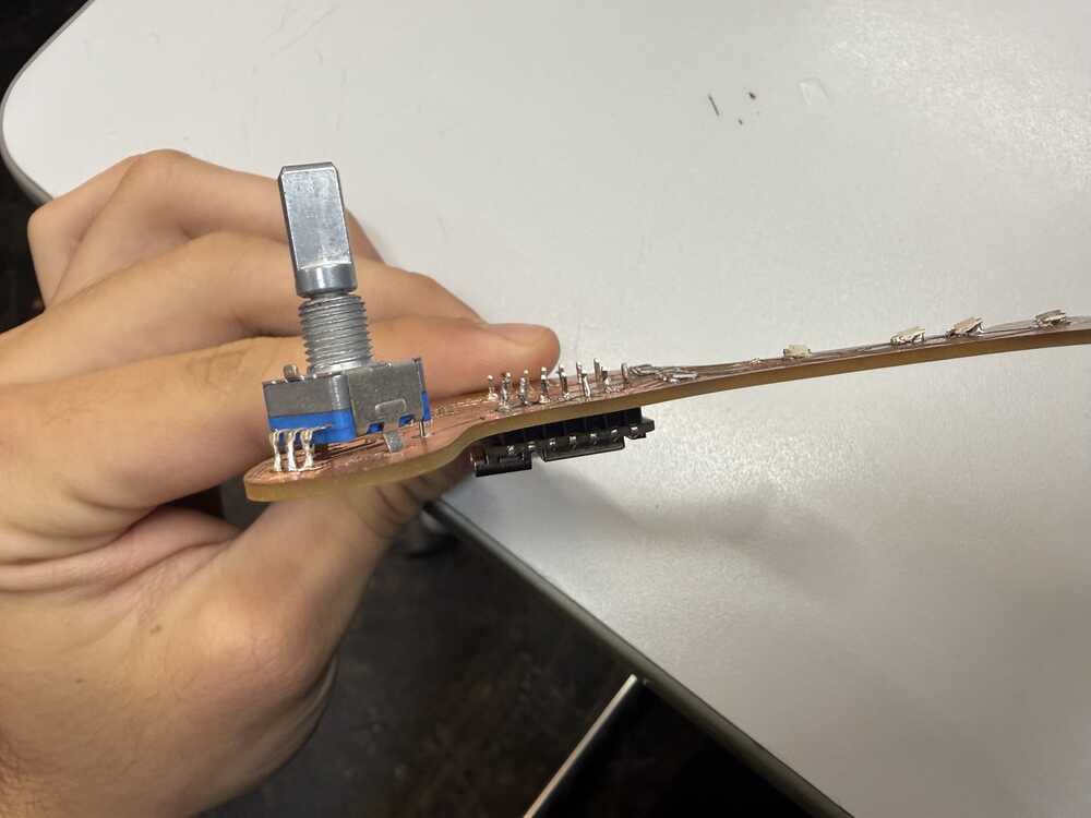
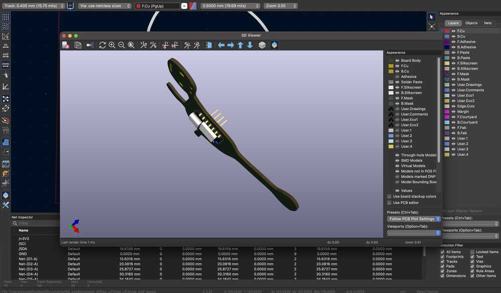
When I moved to the PCB layout, I placed the XIAO on the back side of the board I'd have more spaces for the traces. The rotary encoder and the 4-pin connector just go straight through the board's through holes, nothing special there.
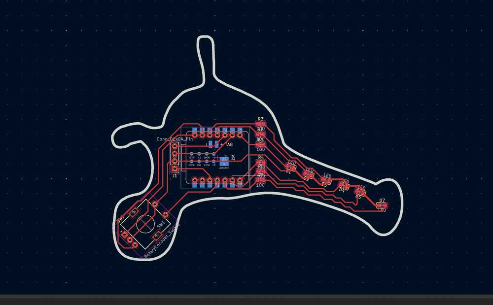
The plan is to solder some headers on the XIOA (I had those on the XIAO I did back in embedded programming week).
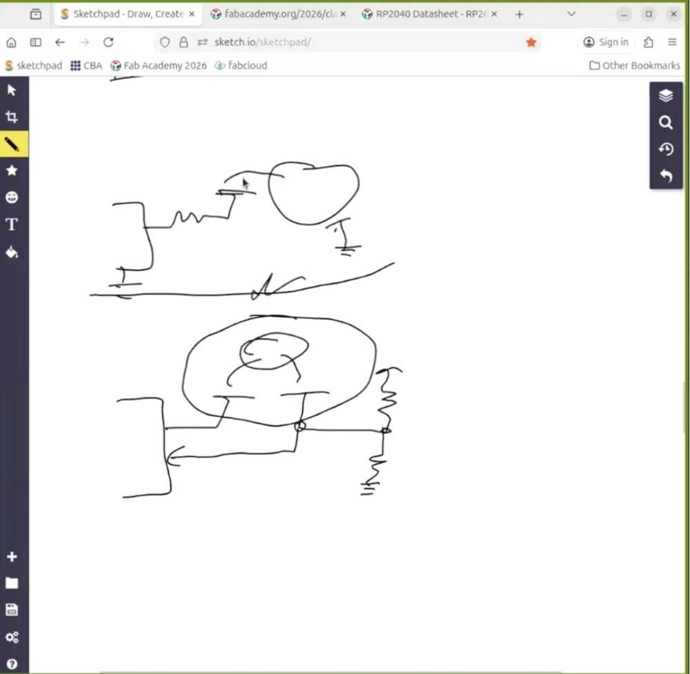
But here's where things got a bit tricky. Because I was routing from front to back, some of the pin assignments ended up getting flipped relative to what I had in the original schematic. Some of the LED connections were going to the wrong GPIO pins, so the schematic needed to be changed.
So I had to go back and update the schematic to match how the traces actually needed to run on the single-sided board. The schematic you see is the corrected version after that fix.
This was how that initial messy schematic looked like originally, but it is natural since this is all a learning journey :D
An important note: the placement of the LEDs here is intentional since they are simulating a how the voltage moves across the neuron through the axon and to the axon terminal, and that's why I the LEDs on the axon will be red and the one on the axon terminal indicating a neuron firing will be green.
Here's how the board looked like in the 3D viewer.
How does the rotary encoder work?
The rotary encoder has three pins that matter: A, B, and a common pin that goes to ground. Internally it has two switches that open and close as you turn the knob, and they're offset from each other by 90 degrees. That offset is how the microcontroller figures out direction.
When you turn clockwise, channel A transitions before channel B. Counterclockwise, it's the other way around. In the firmware, I attach an interrupt to channel A so every time it changes state, the ISR fires and reads both A and B. If they match at that moment, the turn was clockwise so I increment. If they don't match, I decrement.
Both pins use INPUT_PULLUP, so at rest they sit at 3.3V and drop to ground when the switches close. Each click of the encoder is one detent, and I've set 20 clicks as the full input range (0% to 100% input current).
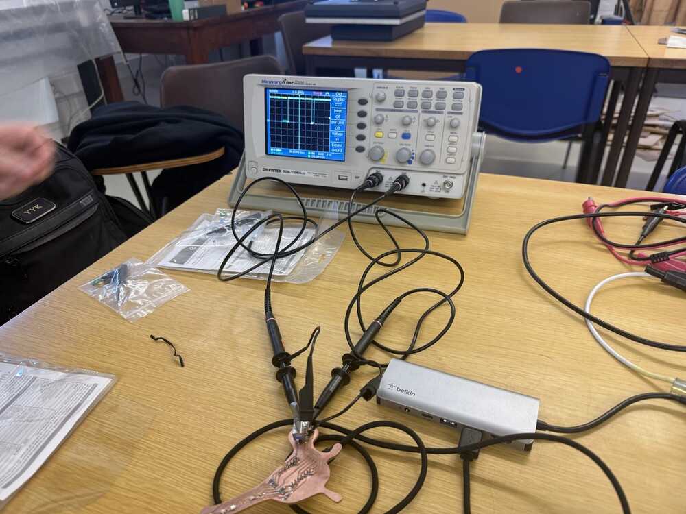
Check out the Group Assignment above to see the readings on an oscilloscope and a more detailed explanation.
What did we move from hardware to software?
The LIF (Leaky Integrate-and-Fire) neuron model is described by this differential equation:
tau * dV/dt = -(V - V_rest) + I_input
What this says: the membrane voltage V is always leaking back toward rest (that's the -(V - V_rest) term), and input current I_input pushes it up. Tau controls how fast the leak happens.
If the input is strong enough to overcome the leak, V climbs until it crosses a threshold, the neuron fires a spike, and V resets back to rest. Then there's a short refractory period where it can't fire again.
In week 6, each piece of that equation was a physical component on the PCB:
- The membrane (V) was the voltage across a capacitor (C_mem = 10uF)
- The leak was a resistor draining that capacitor (R_leak = 100k, giving tau = R*C = 1s)
- The threshold detection was an LM339 comparator watching the capacitor voltage
- The spike was a NE555 monostable pulse
- The reset was a 2N7002 MOSFET pulling the capacitor back to virtual ground
Now in software, each of those maps to a line or two of code:
// The membrane is just a float
float membrane = 0.0;

// The leak + integration is one line of Euler method
membrane += (DT / TAU) * (-membrane + input_current);

// The threshold detection is an if-statement
if (membrane >= THRESHOLD) {
  membrane = 0;        // reset (was the MOSFET)
  in_refract = true;   // refractory period (was the NE555 timing)
}
The Euler integration line is the whole LIF equation discretized. DT is the time step (10ms), TAU is 2.2 seconds. Every loop iteration, it nudges the membrane a little toward the input current, but the -membrane term pulls it back toward zero.
That tug-of-war between input and leak is the entire model.
The trade-off is that the software version doesn't run in continuous time like the analog circuit. It updates every 10ms, so there's a discrete time step. But for demonstrating the neuron model and visualizing its behavior, it works great.
And the physical interface with the encoder and LEDs keeps it feeling tangible rather than just numbers on a screen.
Milling and Soldering the Neuron PCB
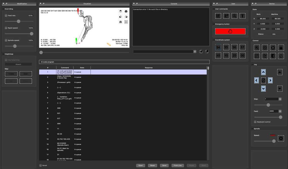
Milling went the same way as week 8: exported Gerbers from KiCad, generated G-code on EasyTrace5000, then ran the isolation routing and board cutout on Candle with height mapping.
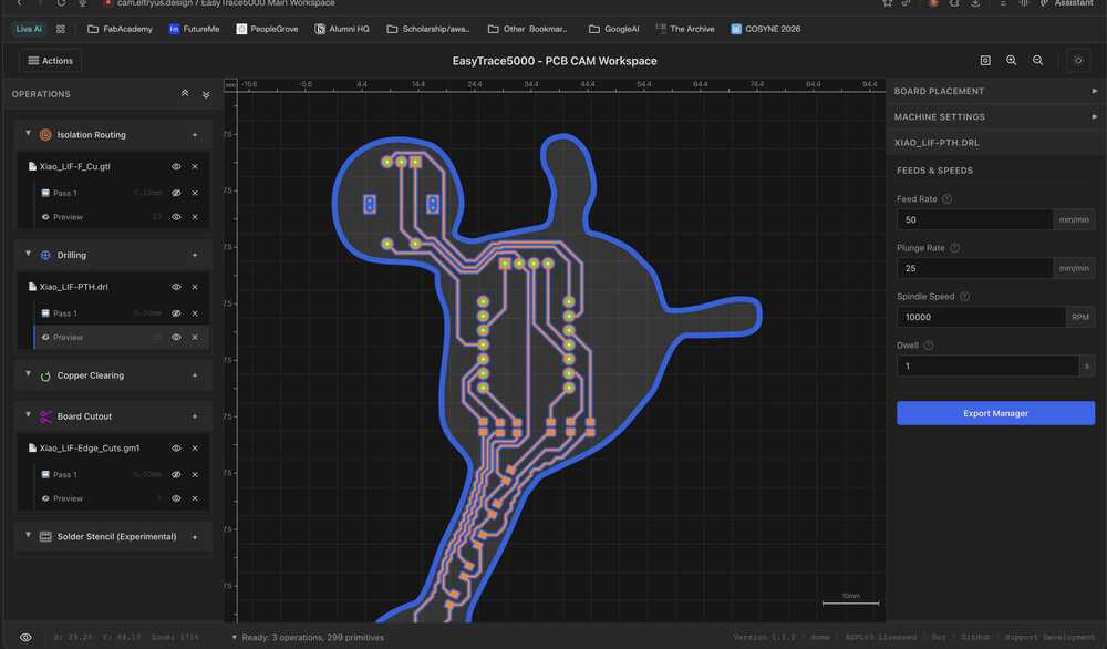
No surprises there since I'd already gone through the whole process once before and thankfully it went smoothly.
I just had to orient it properly so it would fit in the empty space of our board.
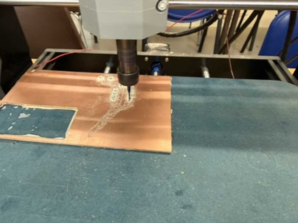
A note: I needed to mill the board again since initially, the board cutout was too narrow at some places that I broke it while remove it from CNC. The Inkscape image I attached is of the edited design, which also gave me more room to make more space between traces.
Soldering was a different story. I started with the XIAO's attached headers, which went fine.
Then the rotary encoder, also fine since those are through-hole, and I tested it on my computer before soldering the LEDs. The test code just counts encoder clicks using the same interrupt logic as the final firmware and prints the position to the terminal:
#include <Arduino.h>

const int ENC_A = D0;
const int ENC_B = D1;
const int MAX_POS = 100;

volatile int encoderPos = 0;
volatile bool lastA = true;

void IRAM_ATTR onEncoderChange() {
  bool a = digitalRead(ENC_A);
  bool b = digitalRead(ENC_B);
  if (a != lastA) {
    encoderPos += (a == b) ? 1 : -1;
    lastA = a;
  }
}

void setup() {
  Serial.begin(115200);
  pinMode(ENC_A, INPUT_PULLUP);
  pinMode(ENC_B, INPUT_PULLUP);
  attachInterrupt(digitalPinToInterrupt(ENC_A), onEncoderChange, CHANGE);
}

void loop() {
  noInterrupts();
  int pos = encoderPos;
  if (pos < 0) encoderPos = 0;
  if (pos > MAX_POS) encoderPos = MAX_POS;
  interrupts();
  pos = constrain(pos, 0, MAX_POS);
  Serial.println(pos);
  delay(50);
}
Turning the knob and watching the position count up and down in the serial monitor confirmed everything was wired correctly.
However, the LEDs and their 500 ohm resistors gave me trouble.
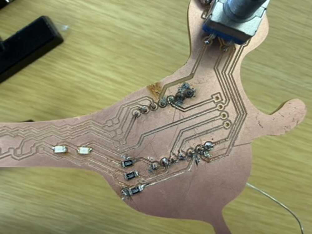
I ruined 3 resistor pads while soldering them by either putting to much heat on one pad that it was removed or connecting two traces with solder, but I had that in mind when designing that all the other LEDs where almost like backup.
Note from future Youssef: I learnt a better way to solder in Japan using liquid flux and a heat gun.
I needed to have minimum 3 LEDs functions: 2 on the axon and 1 in the terminal.
In the end, I only got about half the LEDs working (2 on the axon and the spiking indicator).
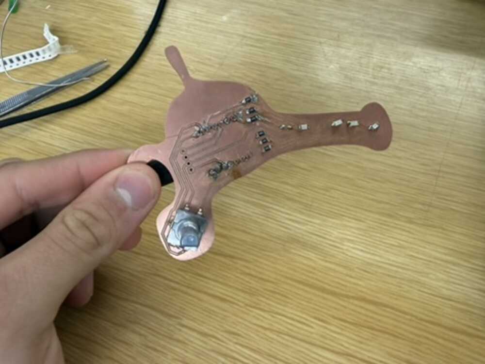
Final Results: How the Board Works?
I wrote the firmware in C++ using PlatformIO with the Arduino framework. The idea was to take the LIF equation from week 6's analog circuit (and the fact that this is one of the most common neuron models) and just do all of it in code on the XIAO ESP32-S3 instead.
Writing the Firmware
I started by setting up the project in PlatformIO and defining all the pin assignments and neuron parameters at the top:
const int ENC_A = D0;
const int ENC_B = D1;
const int LED_MEM_LO = D7;  // membrane low (red)
const int LED_MEM_HI = D8;  // membrane high (red)
const int LED_SPIKE = D9;   // spike flash (green)

const float TAU = 2.2;
const float THRESHOLD = 0.7;
const float DT = 0.01;
const float REFRACT_TIME = 50;
const float SPIKE_FLASH_T = 150;
const int MAX_CLICKS = 20;
TAU controls how fast the membrane charges and leaks. I picked 2.2 seconds because it gives a nice visible ramp when you turn the encoder.
THRESHOLD at 0.7 means the neuron doesn't need to reach full input to fire, which makes the spiking behavior more interesting. DT is 0.01 (10ms loop), and MAX_CLICKS = 20 means 20 encoder detents goes from zero to full input current.
Then the state variables. The encoder vars are volatile since they get modified inside the interrupt:
// Encoder
volatile int clicks = 0;
volatile bool last_a = true;

// Neuron
float membrane = 0.0;
float input_current = 0.0;
bool in_refract = false;
bool spike_lit = false;
unsigned long refract_start = 0;
unsigned long spike_start = 0;
unsigned long sample = 0;
membrane is the neuron's voltage. in_refract tracks whether we're in the dead period after a spike. spike_lit tracks whether the red LED is still flashing. The timing variables store when each event started so we can check if enough time has passed.
The first thing I had to figure out was reading the rotary encoder. I used an interrupt on channel A so the code catches every transition even if the main loop is busy:
void IRAM_ATTR on_encoder() {
  bool a = digitalRead(ENC_A);
  bool b = digitalRead(ENC_B);
  if (a != last_a) {
    clicks += (a == b) ? 1 : -1;
    last_a = a;
  }
}
IRAM_ATTR tells the ESP32 to keep this function in RAM so the interrupt runs fast. The logic is simple: if A changed and A matches B at that moment, the turn was clockwise so increment. If they don't match, decrement. This is the standard quadrature decoding trick.
In setup I enable the internal pull-ups on both encoder pins, attach the interrupt, and free up D7 from UART0 (since GPIO43 defaults to TX on the ESP32-S3):
void setup() {
  Serial.begin(115200);
  pinMode(ENC_A, INPUT_PULLUP);
  pinMode(ENC_B, INPUT_PULLUP);
  attachInterrupt(digitalPinToInterrupt(ENC_A), on_encoder, CHANGE);
  Serial0.end();
  pinMode(LED_MEM_LO, OUTPUT);
  pinMode(LED_MEM_HI, OUTPUT);
  pinMode(LED_SPIKE, OUTPUT);
}
Then in the main loop, I read the encoder click count with interrupts briefly disabled so I don't grab a half-updated value, and normalize it to a 0.0 to 1.0 float:
noInterrupts();
int pos = clicks;
if (pos < 0) clicks = 0;
if (pos > MAX_CLICKS) clicks = MAX_CLICKS;
interrupts();
pos = constrain(pos, 0, MAX_CLICKS);
input_current = (float)pos / MAX_CLICKS;
Before running the neuron math, the loop checks if the refractory period has expired:
if (in_refract && (now - refract_start >= (unsigned long)REFRACT_TIME))
  in_refract = false;
Then the LIF integration only runs if we're not in refractory. This is the same as a real neuron's absolute refractory period where it physically cannot fire again for a short window:
bool spiked = false;
if (!in_refract) {
  membrane += (DT / TAU) * (-membrane + input_current);
  if (membrane < 0) membrane = 0;
That one line is the whole LIF equation (tau * dV/dt = -(V - V_rest) + I_input) discretized into a time step using Euler's method.
DT/TAU is the ratio of the time step (10ms) to the time constant (2.2s), so each step only moves the membrane a tiny amount.
The -membrane term is the leak, always pulling voltage back toward zero (rest). The +input_current term is the excitation from the encoder.
If input is low the leak wins and the membrane just sits near zero. If input is high enough, the membrane climbs until it hits threshold. The clamp to zero prevents it from going negative since real neurons don't go below rest in the basic LIF model.
When it does cross threshold, the neuron fires:
if (membrane >= THRESHOLD) {
  spiked = true;
  membrane = 0;
  in_refract = true;
  refract_start = now;
  spike_start = now;
  spike_lit = true;
  digitalWrite(LED_SPIKE, HIGH);
}
Membrane resets to zero, the refractory flag goes up for 50ms, and the red LED turns on. The spike LED has its own timeout that runs independently:
if (spike_lit && (now - spike_start >= (unsigned long)SPIKE_FLASH_T)) {
  digitalWrite(LED_SPIKE, LOW);
  spike_lit = false;
}
So the LED stays on for 150ms even though the refractory period is only 50ms. That way you can actually see the flash.
For the membrane LEDs, I scale the voltage as a fraction of threshold. The red LED on D7 comes on at 40%, the red LED on D8 at 80%:
float frac = membrane / THRESHOLD;
digitalWrite(LED_MEM_LO, frac >= 0.4 ? HIGH : LOW);
digitalWrite(LED_MEM_HI, frac >= 0.8 ? HIGH : LOW);
So as you turn the knob up, you see one red LED come on first at 40% of threshold, then the second red LED joins it at 80%, and then the green spike LED flashes when it spikes and everything resets. The more input you give it the faster it spikes. This is rate coding, the same thing real neurons do.
Lastly, I stream CSV data over USB serial every loop iteration so I can visualize what's happening:
Serial.print(sample);
Serial.print(",");
Serial.print(input_current, 3);
Serial.print(",");
Serial.print(membrane, 3);
Serial.print(",");
Serial.println(spiked ? 1 : 0);
Four columns: sample number, input current (0 to 1), membrane voltage (0 to ~0.7), and spike flag (0 or 1).
At the end of each loop iteration:
sample++;
delay(10);
The delay(10) is what sets the 10ms time step that DT = 0.01 assumes. The whole loop runs at roughly 100Hz.
This is everything working in action alongside a simple visualizer running on my computer based on the input from the rotary encoder.
As for the simple visualizer in the image, the setup is pretty minimal. I import serial to talk to the board, matplotlib for the plots, FuncAnimation to keep them updating, and deque from collections as a fixed-length scrolling buffer:
import sys
import serial
import matplotlib.pyplot as plt
from matplotlib.animation import FuncAnimation
from collections import deque
Then I open the serial port at 115200 baud with a short timeout so readline doesn't block the animation, and create four deques each capped at 500 samples. When a new reading comes in and the deque is full, the oldest value falls off the left end automatically:
PORT = sys.argv[1] if len(sys.argv) > 1 else "/dev/cu.usbmodem101"
BAUD = 115200
WINDOW = 500

ser = serial.Serial(PORT, BAUD, timeout=0.05)

ts = deque(maxlen=WINDOW)
voltages = deque(maxlen=WINDOW)
currents = deque(maxlen=WINDOW)
spikes = deque(maxlen=WINDOW)
The figure has two subplots sharing the same x-axis. The top one shows membrane voltage in blue with a red dashed line at 1.0 for the threshold. The bottom one shows input current in green. I set fixed y-limits on both so the axes don't jump around while data comes in:
fig, (ax_v, ax_i) = plt.subplots(2, 1, figsize=(10, 6), sharex=True)
fig.suptitle("LIF Neuron — Live", fontsize=14)

line_v, = ax_v.plot([], [], "b-", linewidth=1.2, label="Membrane V")
line_i, = ax_i.plot([], [], "g-", linewidth=1.2, label="Input I")

ax_v.set_ylabel("Membrane Potential")
ax_v.set_ylim(-0.05, 1.15)
ax_v.axhline(y=1.0, color="r", linestyle="--", linewidth=0.8, label="Threshold")
The update function runs on every animation frame. I let it read up to 20 lines per frame so it can catch up if the board has been sending data faster than the plot was refreshing. Each line comes in as four comma-separated values matching the firmware's CSV output:
def update(frame):
    global spike_markers
    lines_read = 0
    while lines_read < 20:
        raw = ser.readline()
        if not raw:
            break
        try:
            parts = raw.decode("utf-8", errors="ignore").strip().split(",")
            if len(parts) != 4:
                continue
            t = int(parts[0])
            i_in = float(parts[1])
            v = float(parts[2])
            sp = int(parts[3])
            ts.append(len(ts))
            voltages.append(v)
            currents.append(i_in)
            spikes.append(sp)
            lines_read += 1
        except (ValueError, UnicodeDecodeError):
            continue
After reading, I redraw both lines and handle the spike markers. Each frame I remove the old spike lines and redraw them from scratch based on whatever is currently in the spikes deque. That way the markers scroll with the window as data ages out:
for m in spike_markers:
    m.remove()
spike_markers = []
for idx, sp in enumerate(spikes):
    if sp == 1:
        m = ax_v.axvline(x=x[idx], color="r", alpha=0.3, linewidth=1)
        spike_markers.append(m)
Finally FuncAnimation calls update every 50ms, which gives a smooth enough refresh without hammering the CPU:
ani = FuncAnimation(fig, update, interval=50, blit=False, cache_frame_data=False)
plt.tight_layout()
plt.show()
ser.close()
The "Advanced" Visualizer (vibecoded with Codex)
Tbh, I wanted a cooler visualizer, so I vibecoded it using OpenAI's Codex. I gave it my firmware's CSV format and described what I wanted alongside context of the previous code I wrote for the visualizer above, roughly along the lines of:
Codex generated the whole thing. It draws the neuron with organic curved branches for dendrites, an irregular blob for the soma, myelin sheaths along the axon, and synaptic terminals at the end.
Everything animates based on the live serial data. The soma displays the current membrane voltage in millivolts right in the center, and there's a firing rate counter in the title bar.
To run it, the code is its own section to download:
pip install pyserial matplotlib
python3 visualizer.py /dev/cu.usbmodem11401
Replace the port with whatever shows up when you run ls /dev/cu.usb*.
Original Design and Code Files
- KiCad Design Files
- Core LIF Simulation Code (+ PlatformIO Setup)
- Simple Voltage + Current Visualizer
- Neuron Visualizer
This week's checklist
- Linked to the group assignment page.
- Documented what you learned from interfacing an input device(s) to your microcontroller and optionally, how the physical property relates to the measured results.
- Documented your design and fabrication process or linked to the board you made in a previous assignment.
- Explained how your code works.
- Explained any problems you encountered and how you fixed them.
- Included original design files and source code.
- Included a 'hero shot' of your board.