This group assignment was about probing the signals coming from an input device using a multimeter and an oscilloscope, actually seeing what the signals look like electrically, not just that the code runs.
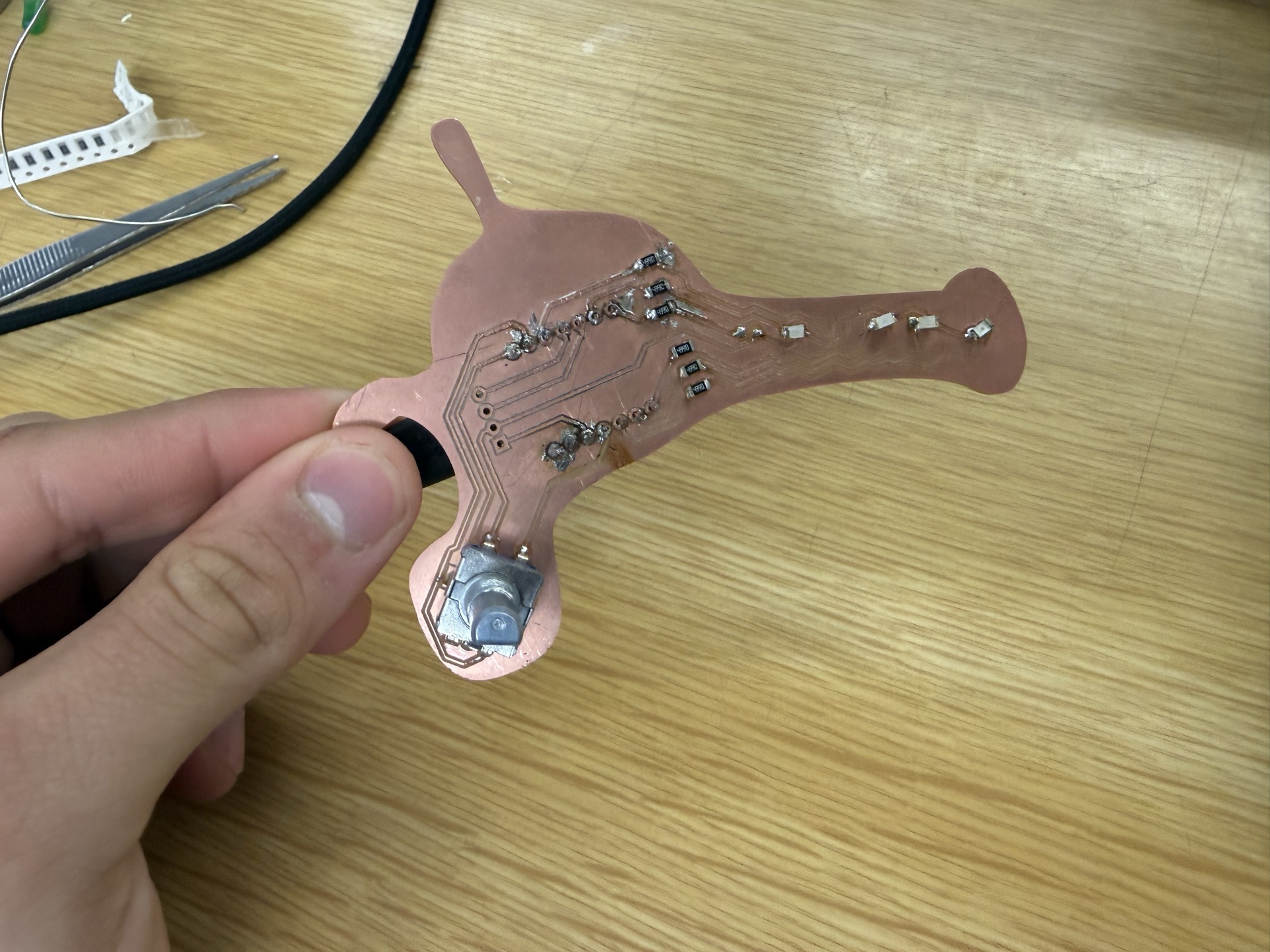
We used the EC11 rotary encoder connected to our XIAO ESP32-S3 board. The encoder was our input device for the individual assignment too, so probing it here helped us understand exactly what the microcontroller is reading from it.
A rotary encoder converts rotation into electrical pulses. Unlike a potentiometer (continuous analog voltage), a rotary encoder outputs two square-wave digital signals (channel A and channel B) 90 degrees out of phase. This is called quadrature encoding.
The order in which the two channels transition tells you the direction of rotation. If A leads B, the knob is turning one way. If B leads A, the other way. The frequency of the pulses tells you speed.
Our encoder is wired to pins D0 (channel A) and D1 (channel B) on the XIAO, with internal pull-up resistors enabled.
Before looking at signals in motion, we measured static voltage levels on the encoder pins with the multimeter. With pull-ups enabled, both channels sit at 3.3V (HIGH) when the encoder is at rest. The encoder's internal switches pull them LOW when a detent is engaged.
We measured:
Pull-up configuration working, clean rail-to-rail signals (0V to 3.3V).
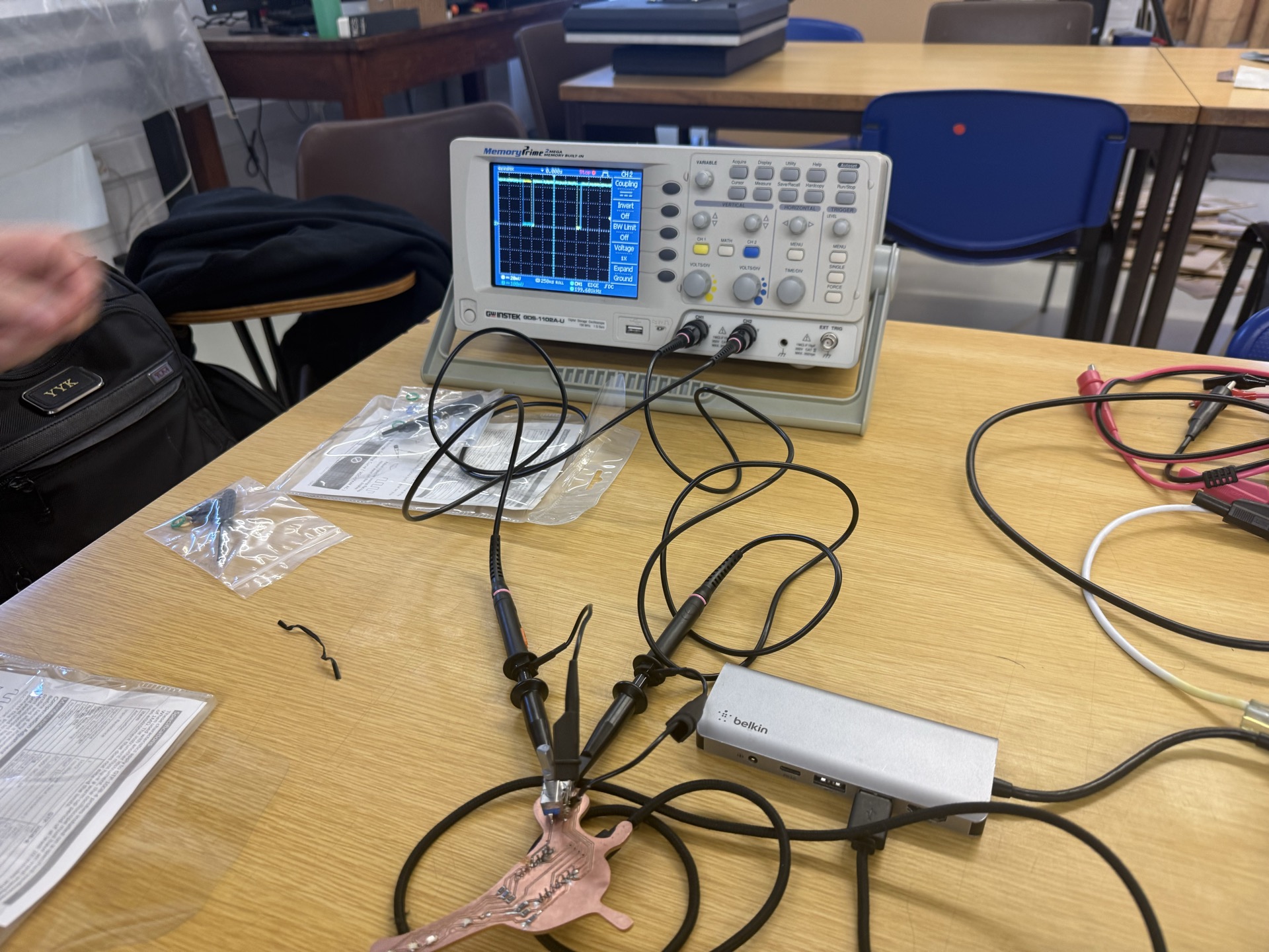
The oscilloscope lets us see both channels simultaneously and observe the phase relationship that encodes direction.
We connected the oscilloscope's two channels to the encoder outputs:
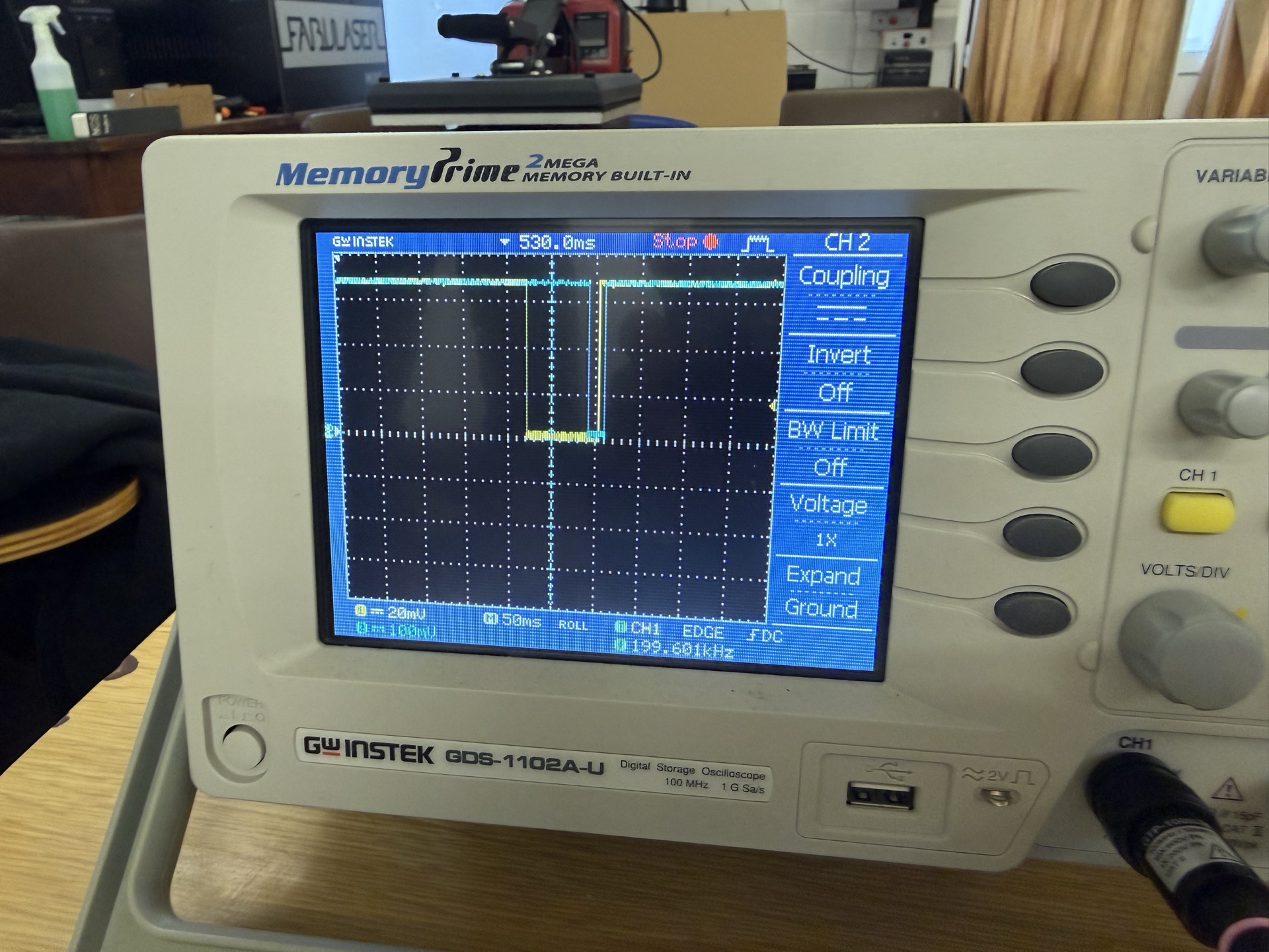
Turning the encoder clockwise, channel 2 (blue) transitions first, followed by channel 1 (yellow). The leading channel tells the microcontroller which direction the knob is turning.
Turning counterclockwise, the order reverses: channel 1 (yellow) transitions first and the pulses are wider at slower rotation speeds.
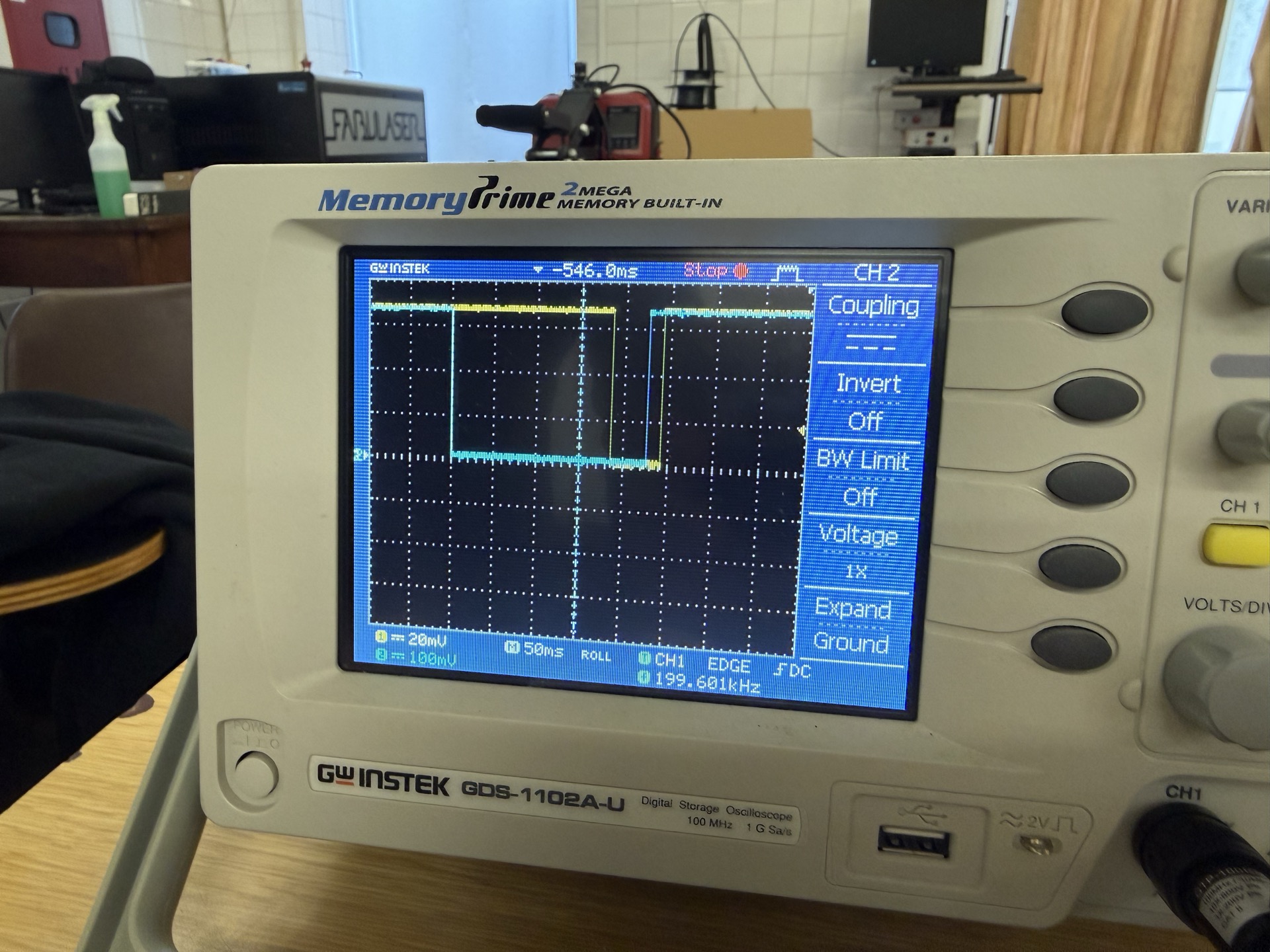
The phase relationship between the two channels clearly flips depending on rotation direction. The firmware's interrupt handler uses exactly this — it reads both pins on a CHANGE event and determines direction from whether A equals B.
The transitions are sharp, 0V to 3.3V with minimal bounce. The internal pull-ups on the ESP32-S3 are doing their job. Some cheaper encoders need debouncing in software but ours worked fine with a simple interrupt.
Pulse width correlates to rotation speed. Slow rotation = wide pulses, fast rotation = narrow, tightly packed pulses.
The firmware reads the encoder with a hardware interrupt on channel A. The code lives in our PlatformIO project (Arduino framework on the XIAO ESP32-S3):
const int ENC_A = D0;
const int ENC_B = D1;

volatile int clicks = 0;
volatile bool last_a = true;

void IRAM_ATTR on_encoder() {
  bool a = digitalRead(ENC_A);
  bool b = digitalRead(ENC_B);
  if (a != last_a) {
    clicks += (a == b) ? 1 : -1;
    last_a = a;
  }
}
Every time channel A changes state (the transitions we saw on the scope), the interrupt fires. It reads both channels: if A equals B at that moment, the knob is turning clockwise (increment). If not, counterclockwise (decrement).
This matches exactly what we observed on the oscilloscope. When blue (B) leads yellow (A) on a clockwise turn, A and B are in the same state at the instant A transitions, so the ISR adds a click. On a counterclockwise turn the phase flips and the ISR subtracts.
The pins are set up with internal pull-ups and the interrupt is attached on CHANGE, which is why the scope showed clean rail-to-rail edges with no extra circuitry needed:
pinMode(ENC_A, INPUT_PULLUP);
pinMode(ENC_B, INPUT_PULLUP);
attachInterrupt(digitalPinToInterrupt(ENC_A), on_encoder, CHANGE);| What we probed | Tool | What we found |
|---|---|---|
| Static pin voltage | Multimeter | 3.3V at rest (pull-ups working), ~0V when encoder switch closes |
| Quadrature phase (CW) | Oscilloscope | Channel B (blue) leads channel A (yellow) |
| Quadrature phase (CCW) | Oscilloscope | Channel A (yellow) leads channel B (blue), wider pulses at slow speeds |
| Signal quality | Oscilloscope | Clean rail-to-rail transitions, minimal bounce |
The oscilloscope lets you see the relationship between signals that a multimeter can't. A multimeter tells you the voltage is correct, but only the scope reveals the timing and phase that make quadrature encoding work.