
Week 07
Week 07: Computer Controlled Machining
I learned CNC machining by designing Syrian mosaic geometry and a Damascus Gate-inspired panel, then moving the model through Fusion CAM and machining prep.
This week was to make something BIG! While in Barcelona I was inspired by the amazing Gaudi architecture, and thought to make something big that related to my culture. I decided to create something inspired by the famous Damascus Mosaics.

Not necessarily the best pic representing the Gaudi Architecture though.
One thing I love about Neil is how he interacts with the people who don't speak English well. He always repeats, well you English is much better than my [mentions their language], kinda awesome.
Group Assignment: Safety, Operation, and Testing of the Ouplan Steel 3020
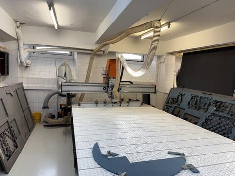
Before arriving at FabLab Benfica, I was excited to try out the CNC Machine, honestly, because it was the biggest machine in the lab.
During the global session, Neil warned us that it is up there as one of the most dangerous machines in the FabLab, so I knew I got to take our safety training seriously. You can read more about it in our group assignment.
One that really stood out is resisting the urge to peak above the cut to see what's happening while the machine is actively cutting. Often times, a person gets curious about the cut either to check on the machines work or to stare at the beauty of the piece they're creating :)
One noteworthy issue we had with out machine that I will talk about later on in my individual assignment section is the leak in the compressor, which delayed the completion of this assignment by 3 weeks.
After getting the safety training from Andre, we went on to design a testing board to test for different aspects of our Ouplan inspired by Jason Goodman's assignment. I won't go into deep details of designing the board since that has already been documented in our group assignment.
Here are the settings we used and that worked for the test cut:
| Setting | Value |
|---|---|
| Tool type | 6 mm flat end mill |
| Material | MDF |
| Number of flutes | 1 |
| Spindle speed | 18,000 rpm |
| Cutting feedrate | 4,000 mm/min |
| Plunge feedrate | 600 mm/min |
Learnings
Coming into this week, I had never used a CNC machine before. Laser cutting felt manageable because the tool is a beam of light you cannot touch, but CNC machining involves a spinning bit physically carving through material, and as Neil emphasized during the session, it is one of the most dangerous machines in the FabLab.
A student has died from a CNC accident before. That immediately set the tone: safety is not optional here.
This section combines what I learned from the global session, the Fab Academy class page, and my own research to fill in the gaps. The session was led by two guests: Tony Schmitz and Tom Bodett, alongside Neil. If you are new to CNC machining like I was, this should give you a solid foundation.
The People Who Led the Session
Tony Schmitz is a Professor of Mechanical, Aerospace and Biomedical Engineering at the University of Tennessee, Knoxville, and Director of the Machine Tool Research Center.
His research focuses on machining dynamics, tool wear, metrology, and advanced manufacturing. He is also the Director of the Southeastern Advanced Machine Tools Network (SEAMTN), a consortium working to strengthen the US machine tool industrial base.
He brought the deep technical knowledge on machining science to the session, covering everything from tool materials and cutting mechanics to speeds, feeds, and vibration dynamics.
Tom Bodett is someone you might recognize from Motel 6 commercials or NPR's Wait, Wait... Don't Tell Me!, but he is also a lifelong woodworker. He co-founded HatchSpace, a nonprofit woodworking school and community workshop in Brattleboro, Vermont. Before his writing and broadcasting career, he spent a decade as a contractor in Alaska. Tom brought the craft perspective to the session. He does not use CNC machines.
He loves making things with his hands because, to him, CNC does not feel like making. His takeaway, and one that stuck with me: "When a machine is done, you are not." The machine executes, but the craft is in the design, the setup, and the finishing.
Machining Fundamentals: How Material Gets Removed
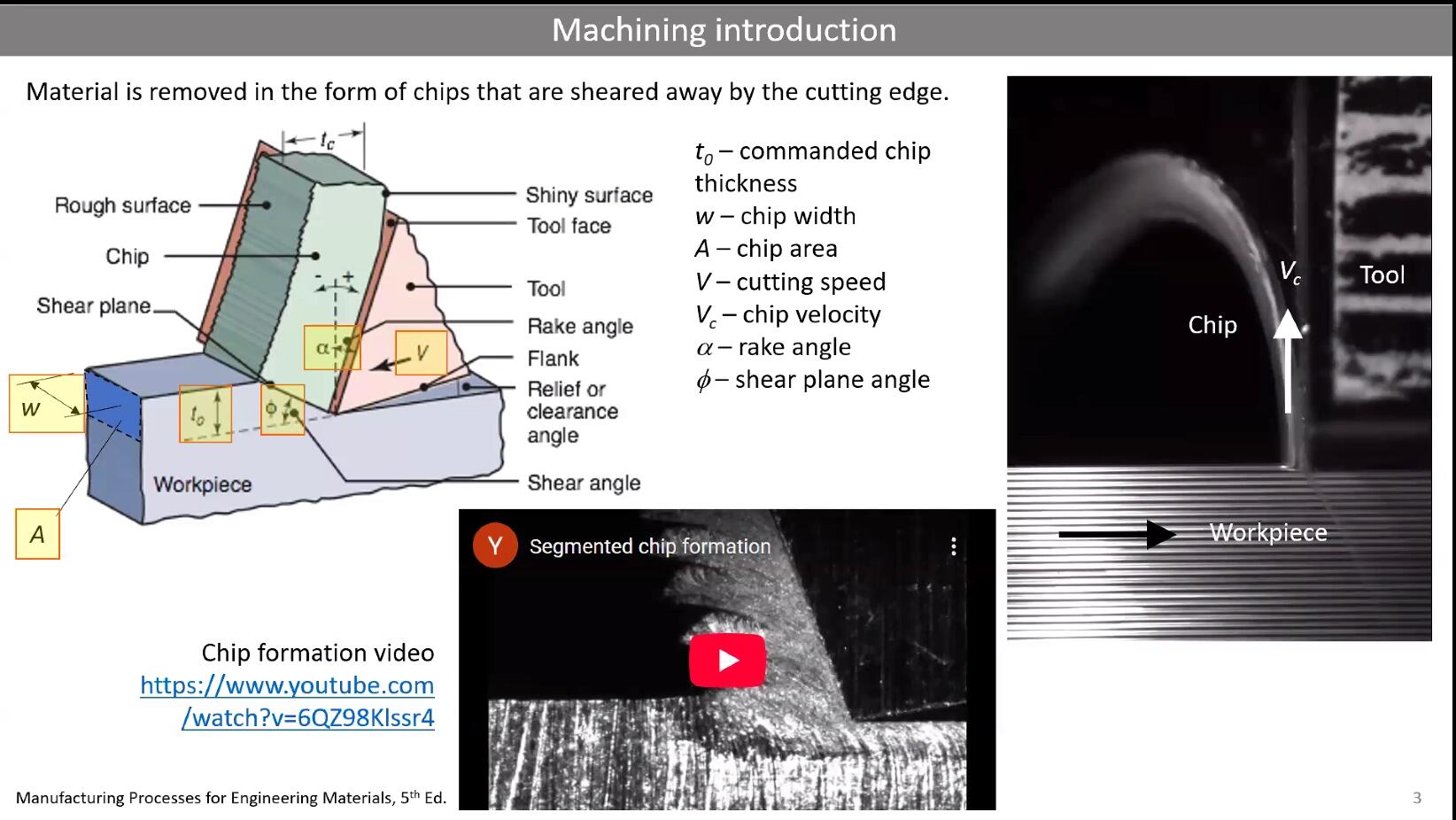
At its core, CNC machining is subtractive manufacturing. A spinning cutting tool moves along programmed paths and removes material chip by chip. When material is removed, things get hot, and that heat is what wears tools out over time.
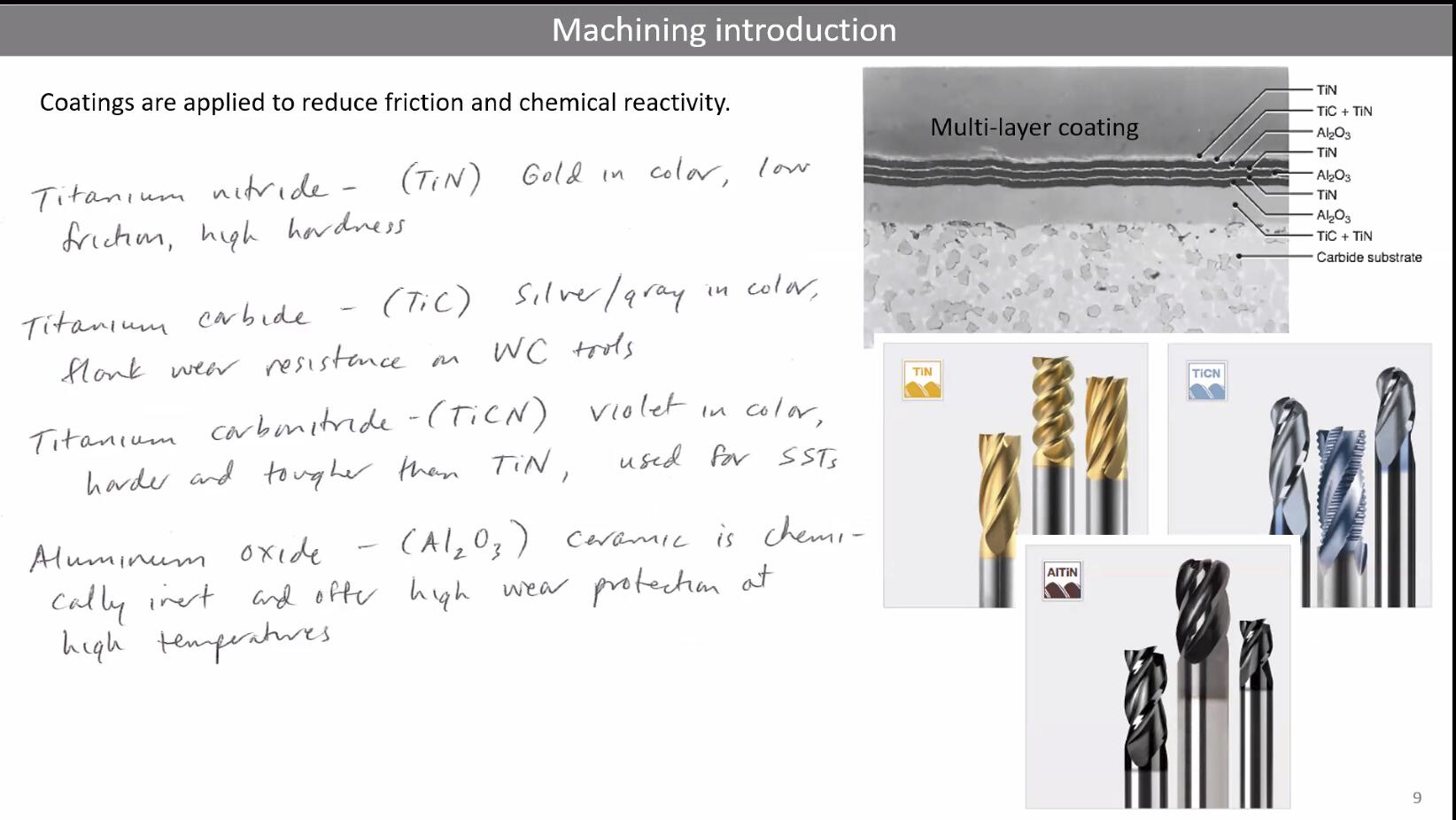
The two main tool materials are high-speed steel (HSS) and carbide. HSS is cheaper and works fine for softer materials like wood, but carbide holds its edge much longer and is better for harder materials. You can also apply coatings like titanium nitride to reduce degradation and extend tool life.
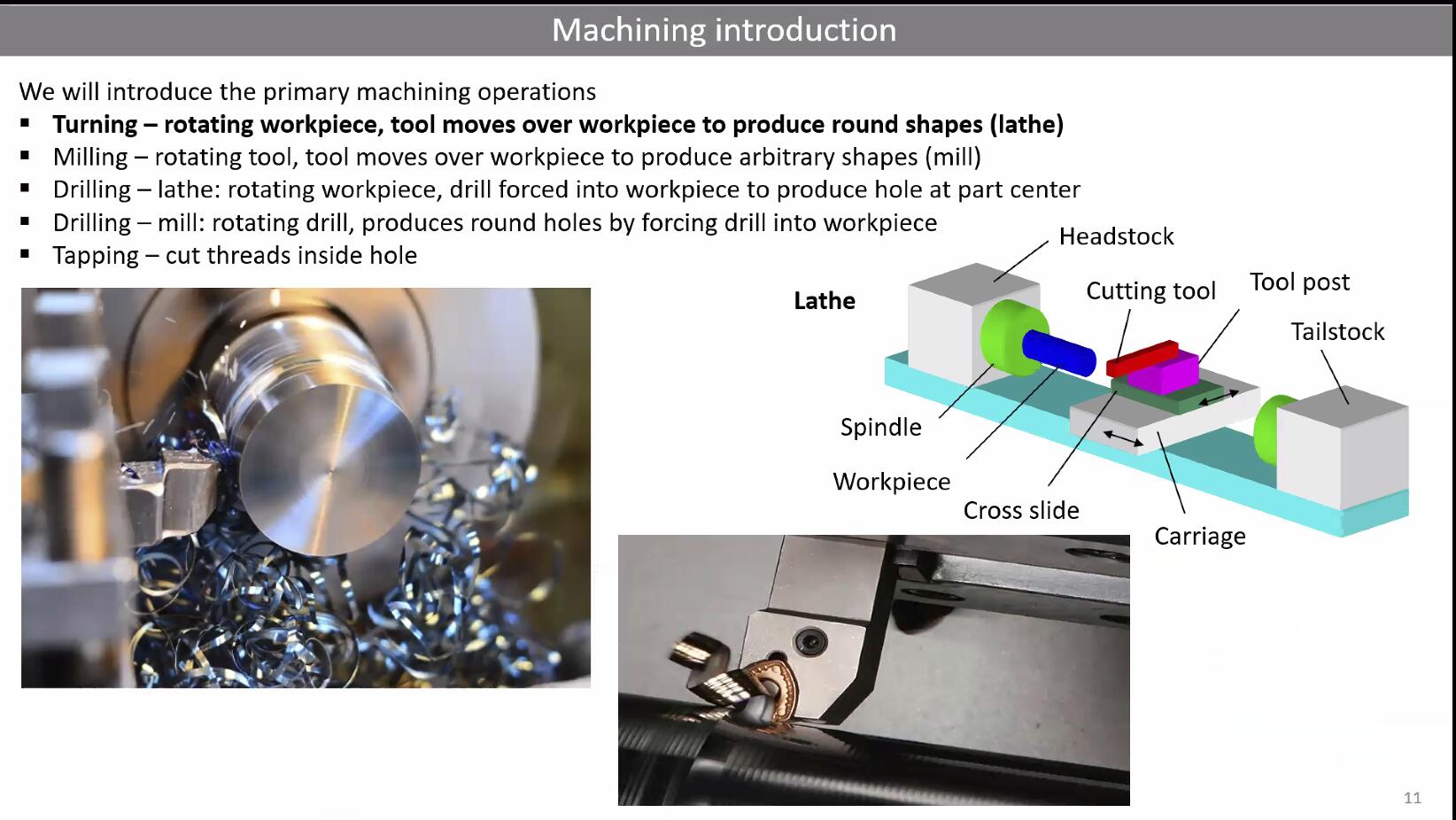
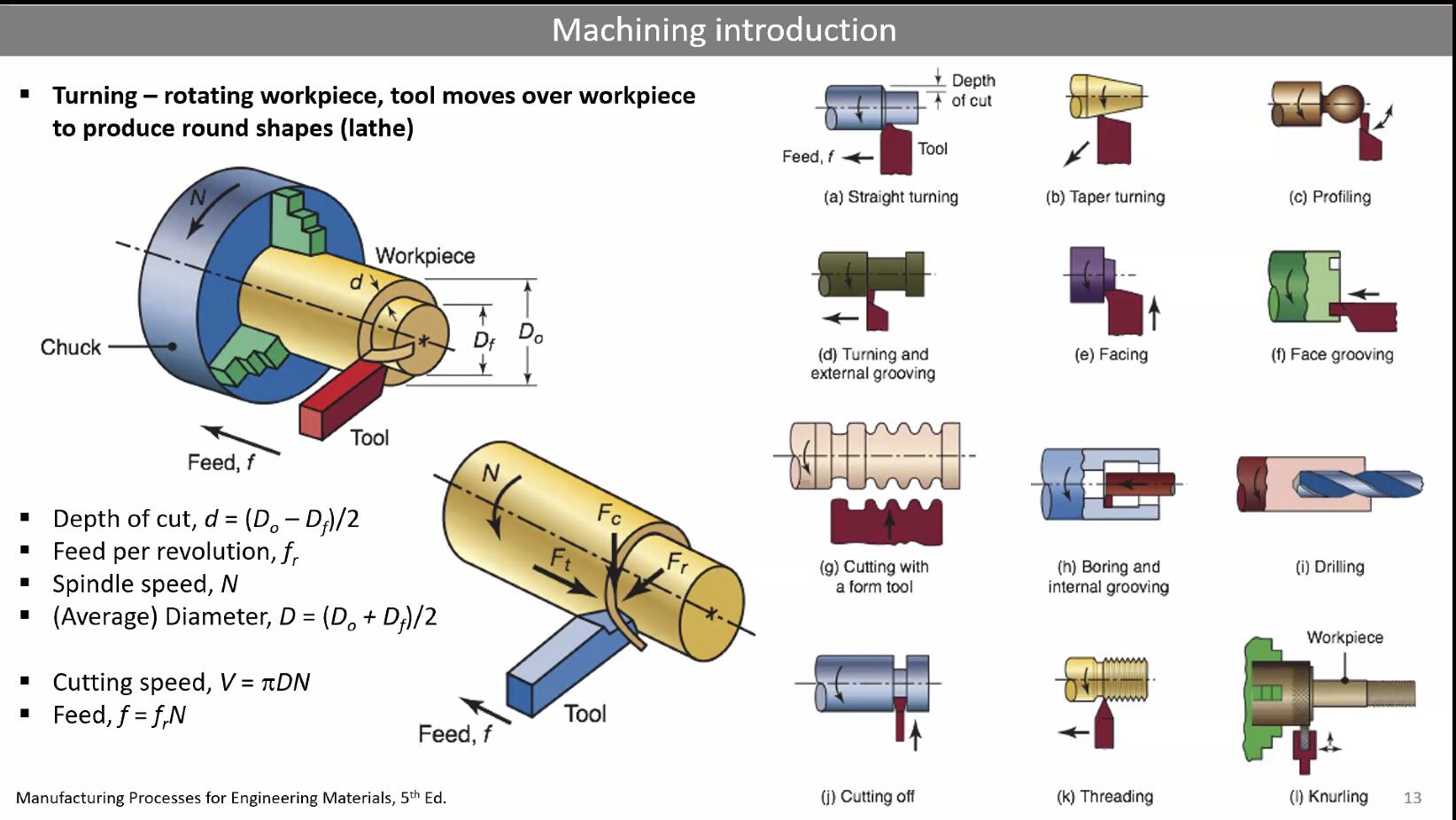
Cutting operations fall into several categories: turning (rotating the workpiece against a stationary tool), milling (rotating the tool against a stationary workpiece), drilling, and tapping. For our CNC routers in the FabLab, we are mostly doing milling.
Axes and Complexity
CNC machines are classified by how many axes of movement they have:
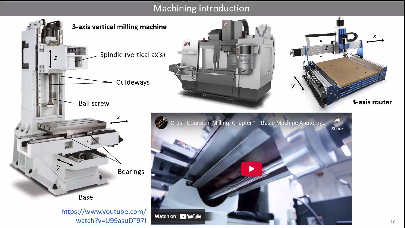
- 3-axis: The tool moves in X, Y, and Z. This is what most FabLab CNC routers are. The tool always points straight down.
- 4-axis: Adds rotation around one axis, allowing you to machine cylindrical or wrapped surfaces.
- 5-axis: Adds rotation around two axes, enabling the tool to approach the workpiece from almost any angle. This is what you need for truly complex 3D surfaces.
For this week's assignment, we are working with a 3-axis machine, which means we need to think carefully about what geometries are actually machinable from above.
Tool Geometry: Flutes, Collets, and Cutting Edges
The cutting edges on a milling bit are called flutes (sometimes referred to as teeth). More flutes means a smoother finish but slower chip evacuation. Fewer flutes means faster material removal but rougher surfaces. For wood on a CNC router, 1 or 2 flute end mills are common.
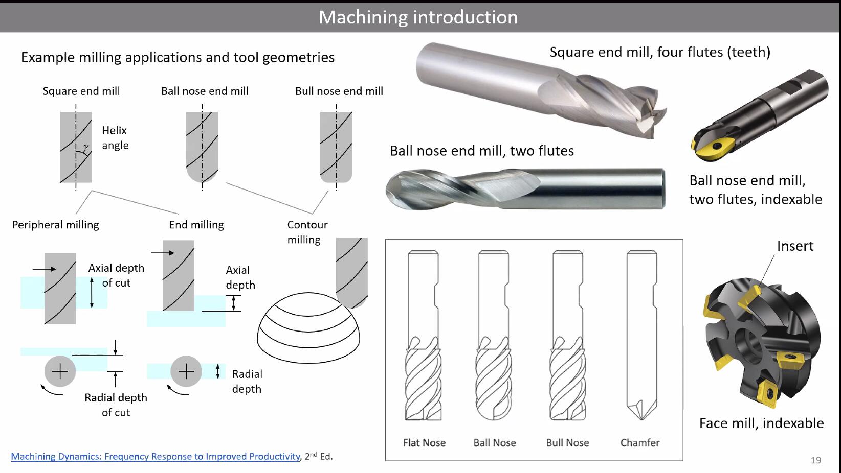
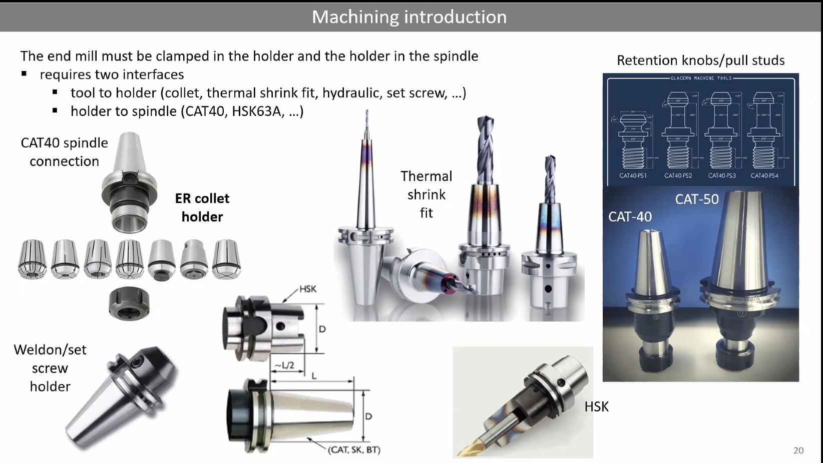
Tools are held in the spindle using collets. In our lab, we most likely use ER collets, which are a standard system that can grip a range of shank diameters.
Another critical concept is up-cut vs down-cut bits. An up-cut bit pulls chips upward and away from the cut, which is great for chip clearing but can cause splintering on the top surface of plywood. A down-cut bit pushes chips downward, giving you a clean top edge but potentially causing issues at the bottom. Compression bits combine both: down-cut at the top and up-cut at the bottom, but they can generate more heat and even cause wood to catch fire if feeds and speeds are wrong.
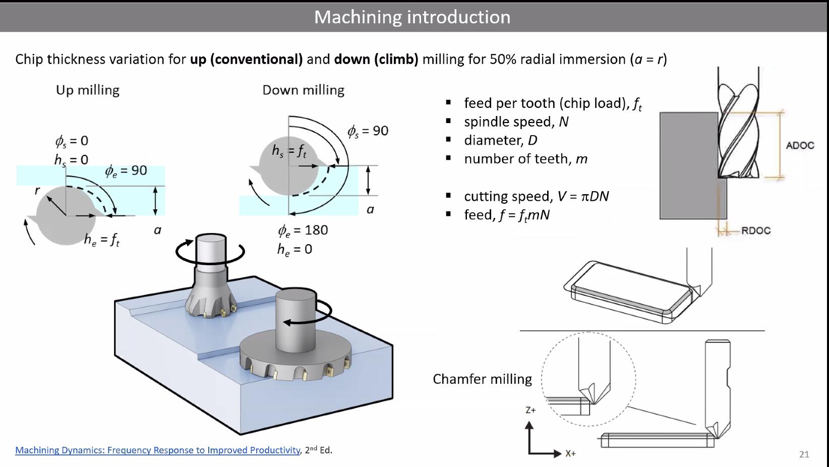
Conventional vs Climb Milling
This distinction matters a lot for surface quality:
Conventional (up) milling: The tool rotates against the direction of feed. Chip thickness starts at zero and increases. This is safer on machines with backlash but gives a rougher surface.
Climb (down) milling: The tool rotates in the same direction as the feed. Chip thickness starts thick and decreases. This produces smoother surfaces and is generally preferred on rigid CNC machines.
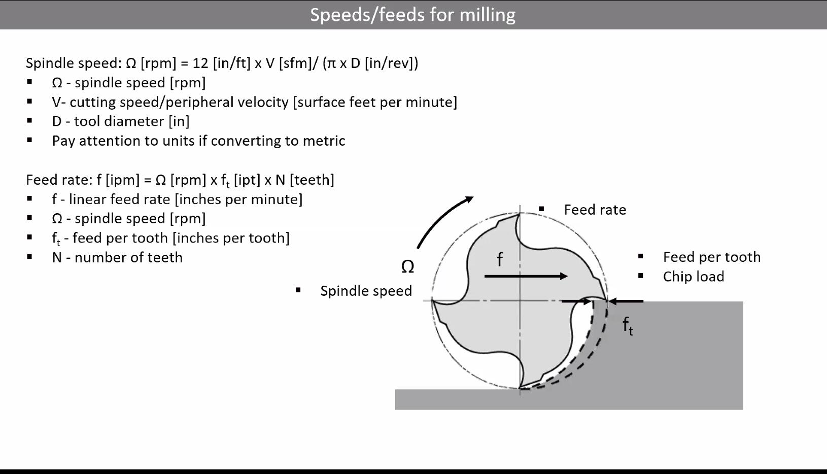
Speeds and Feeds
Speeds and feeds are the decisions you make about how fast the spindle rotates (RPM) and how fast the tool moves through the material (feed rate). Getting these wrong means poor surface quality, broken tools, or even dangerous situations.
The key concept is chip load, which is how much material each flute removes per revolution. For wood on a standard CNC router, chip loads typically range from 0.001" to 0.010". The formula is:
Feed Rate = RPM x Number of Flutes x Chip Load
Cutting tool manufacturers provide tables with recommended speeds and feeds, but these are generic starting points. You need to adjust based on your specific machine's rigidity, the actual material, and the tool condition. With harder materials, you reduce cutting speed.
Step-over (how much the tool moves sideways between passes) and step-down (how deep each pass cuts) also matter. A general rule: step-over should be less than half the tool diameter for a good surface finish. Less step-over means better surface quality but longer machining time.
Working with Wood
Everything about metal machining applies to wood, but with some wood-specific considerations:
Grain direction matters. Wood has lighter grain from summer growth and darker grain from winter growth. Cutting across vs along the grain produces different results.
Plywood is excellent for CNC because it is flat and dimensionally stable. However, since it is made of veneer layers, cutting can cause splintering at the edges. This is where down-cut or compression bits help.
Other materials discussed in the class include MDF (consistent but dusty and not structural), OSB (cheap but rough), MDO (great paintable surface), Valchromat (colored MDF, beautiful but expensive), foam insulation (easy to cut, great for prototyping), HDPE, polycarbonate, and even aluminum composites.
Toolpaths and CAM
CAM (Computer-Aided Manufacturing) software converts your 3D design into toolpaths, which are the specific paths the cutting tool follows. Key toolpath concepts include:
Roughing vs finishing: Rough passes remove bulk material quickly with larger step-overs. Finish passes use smaller step-overs for a smooth final surface.
Adaptive clearing: A modern strategy where the tool follows a path that maintains consistent chip load, reducing stress on the tool and allowing faster overall material removal.
Ramping: Instead of plunging straight down into the material (which is hard on the tool), the tool enters at an angle.
Tabs: Small bridges of material left uncut to keep parts attached to the stock sheet. Without tabs, a part can come loose mid-cut and become a projectile. You cut the tabs off by hand afterward.
Nesting: Arranging multiple parts on a single sheet to minimize waste.
CAM software options include Fusion 360 (most popular in FabLabs), VCarve Pro, FreeCAD, Mastercam, and mods (an open-source system developed in the Fab community).
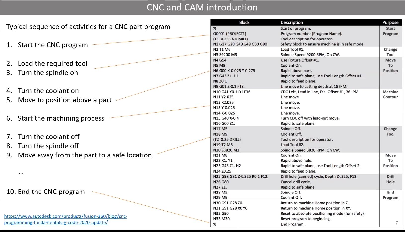
G-Code: What the Machine Actually Reads
The CAM software outputs G-code, a line-by-line instruction set that tells the machine exactly where to move. Some important G-code commands:
- G01: Linear move at a specified feed rate, one of the most common commands.
- G83: Pecking cycle for drilling, where the tool retracts periodically to clear chips from the hole.
- G54: Work coordinate offset, which tells the machine where your part's origin is relative to the machine's home position. Your part's origin can be different from the machine's origin, and G54 bridges that gap.
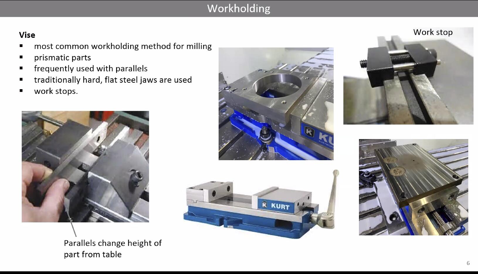
Fixturing: Holding Your Work Down
How you secure the workpiece to the machine bed is critical. If the material moves during cutting, everything goes wrong. Methods covered in the session:
Clamps and toe clamps: Physical clamps bolted to the machine bed. There are lots of configurations for toe clamping.
Screws: Screwing the workpiece directly to a sacrificial board.
Vacuum tables: For large pieces of plywood, a vacuum system holds the sheet flat. Works well for full sheets but can lose hold on small cutouts.
Tabs and picture frames: Tabs keep parts connected to the stock. A picture frame border around your entire cut area adds extra rigidity.
Adhesives and wedges: Double-sided tape or hot glue for smaller pieces.
The work coordinate system also enables you to flip your part over for two-sided machining, using the G54+ offset table to maintain alignment.
Joints for Assembly
Since this week is about making something BIG, assembly is a major consideration. Types of joints discussed:
Finger joints: Interlocking rectangular tabs.
Floating tenons: Like dowels but flat pieces of wood, useful when you have many joints.
Dovetail joints: Angled interlocking joints, very strong.
Knapp joints: A specific interlocking joint design.
CNC does not do horizontal cuts well, so joint designs need to account for the tool always approaching from above.
For fastening, options include wood glue (PVA is good, epoxy is stronger), and screws. The 50 Digital Joints PDF and The Joinery are great references for joint inspiration.
Safety
Neil was very serious about this and so was our lab. Key safety rules:
A student has died from a CNC machine accident. This is not hypothetical danger.
Your hand is never a tool. Never reach into the machine while it is running. Turn it off first.
CNC cutting produces kerf (material removed by the width of the tool), similar to laser cutting, which affects dimensional accuracy.
Always wear appropriate PPE: safety glasses, hearing protection, and avoid loose clothing or jewelry.
Never leave a running CNC machine unattended.
Designing Something BIG
To start off, my idea for this week was to create a design that was inspired by my heritage being from Syria. I wanted to combine that idea alongside utilizing AI to help me in 3D designs. That leads to the first design…
Designing Syrian Mosaic Tiles Through Code
A very popular Syrian design pattern found across Syrian buildings, furniture, decorative items, etc… is the Damascus mosaic tiles, something that looks like the following:
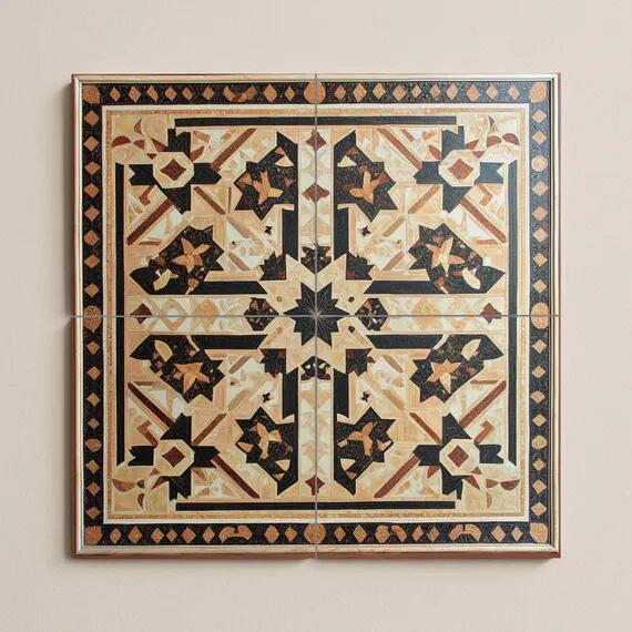
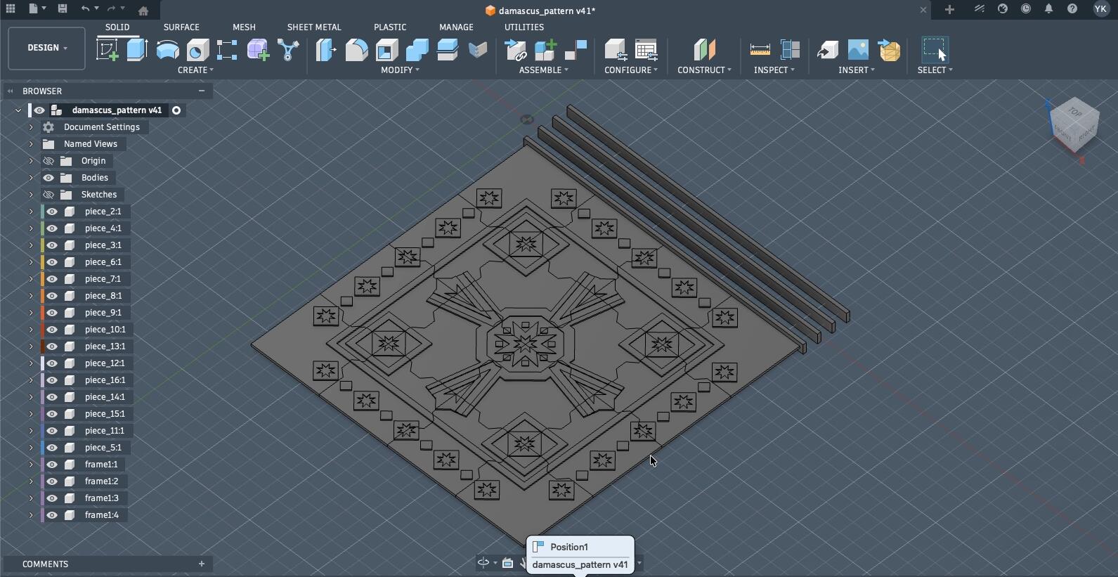
Those designs are very popular across the Arab Middle East, North Africa, and Islamic Iberia (Spain and Portugal), and it is common to find them hanged on walls or part of the tiles themselves. The goal was to create a 1.1 * 1.1 m frame filled with Damascene mosaic tiles (includes the frame).
Since it is a specific geometric pattern, I though I could work with Codex to generate code that'd generate this design.
Codex would generate the mosaic tile pattern, and on Fusion 360, I'll turn that design into a parametric 3D model, where the design is a set of tiles that fit together as a puzzle inside a frame.
Here's a summed up prompt I gave to Codex to generate the following design as an SVG. An important note, this isn't the exact prompt used on the first try since the final output was generated after a conversation with the AI:
Codex doesn't generate patterns out of thin air, geometric patterns are essentially a combination of mathematical equations that could be solved and generated through code. Thus, it generated a Python script the generated the following design:
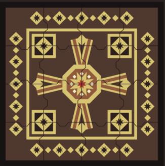
It generated that SVG file alongside 16 other files for each piece of the puzzle. I will walk you through the code written by Codex to generate this design.
What Codex generated is about 560 lines of Python with no external dependencies, just math and pathlib. It writes raw SVG files by string-formatting coordinates, which is surprisingly clean once you look at how it's organized.
Setting the stage with constants. The whole composition is defined in a handful of numbers at the top of the file:
PANEL = 1000.0
FRAME = 0.0
OPENING = PANEL - 2 * FRAME
GRID = 4
CELL = OPENING / GRID
TOOTH_SPAN = 66.0
TOOTH_NECK = 30.0
TOOTH_DEPTH = 22.0
So the whole design the script produces is 1000 mm square (1 m × 1 m), which is the inside of the frame. I'm designing the outer wooden frame itself separately in Fusion 360, so the Python side doesn't need to reserve any space for it, which is why FRAME = 0. The 1 m opening is divided into a 4×4 grid, which gives each tile a 250 mm cell (so each puzzle piece is roughly 250 × 250 mm before the interlocking tabs are added). The TOOTH_* parameters control the shape of the interlocking bumps between pieces. The nice thing is that changing any of these numbers re-flows the entire design, which is exactly the parametric behavior I was hoping for.
Little geometry helpers. Before doing anything pretty, Codex builds a small library of primitives. The one I think is the cleanest is regular_polygon, which drops N points around a circle:
def regular_polygon(cx, cy, radius, sides, rotation_deg=0):
    return [
        (
            cx + radius * math.cos(math.radians(rotation_deg + 360 * idx / sides)),
            cy + radius * math.sin(math.radians(rotation_deg + 360 * idx / sides)),
        )
        for idx in range(sides)
    ]
On top of that sits star_points, which alternates between an outer and an inner radius to draw the 8-pointed stars that show up all over the border and at the center. diamond(cx, cy, r) is just regular_polygon(..., sides=4), and rotate_point / rotate_points are used later to spin things around the panel's center. Every Damascene motif in the file is built from combinations of these.
Making the pieces actually interlock, two tiny functions assign each internal edge either a tab (+1), a slot (−1), or a flat edge (0), based purely on the row and column indices:
def right_edge_sign(row, col):
    if col >= GRID - 1:
        return 0
    return 1 if (row + col) % 2 == 0 else -1

def bottom_edge_sign(row, col):
    if row >= GRID - 1:
        return 0
    return 1 if (row + 2 * col) % 2 == 0 else -1
A piece's top edge is just the negative of the piece above it, and its left edge is the negative of the piece to its left, so a tab on one side is always guaranteed to meet a matching slot on the neighbor. piece_outline(row, col) then walks the four edges of a cell and injects the bump geometry from top_edge_points, right_edge_points, etc., producing a single closed polygon for each of the 16 pieces:
def piece_outline(row, col):
    x0, y0 = tile_origin(row, col)
    x1 = x0 + CELL
    y1 = y0 + CELL
    signs = piece_signs(row, col)

    top = top_edge_points(x0, x1, y0, signs["top"])
    right = right_edge_points(x1, y0, y1, signs["right"])
    bottom = list(reversed(bottom_edge_points(x0, x1, y1, signs["bottom"])))
    left = list(reversed(left_edge_points(x0, y0, y1, signs["left"])))
    return top + right[1:] + bottom[1:] + left[1:]
No two pieces have the same outline, but the whole set slots back together into a perfect square.
The decorative layers. The ornamental pattern is built as a stack of named layers, each returned by its own layer_* function. For example, the four slanted arm bands that pull the eye toward the center are defined once and then rotated around the panel 0°/90°/180°/270°:
def layer_arm_bands(width=38):
    elems = []
    base_left = wide_segment((456, 248), (495, 410), width)
    base_right = wide_segment((544, 248), (505, 410), width)
    for angle in [0, 90, 180, 270]:
        elems.append(polygon(rotate_points(base_left, angle)))
        elems.append(polygon(rotate_points(base_right, angle)))
    return elems
That's where the "diagonal geometry that pulls the eye toward the center" from my prompt actually comes from. The rest of the layer functions follow the same pattern:
layer_border_chain / layer_border_insets: the rows of diamonds and 8-pointed stars around the border
layer_inner_frame_outer / _inner: the rectangular frame just inside the border
layer_corner_boxes, layer_corner_diamonds, layer_corner_rosettes: the four decorated corner squares
layer_center_octagon_outer / _inner, layer_center_star, layer_center_core, layer_center_satellites: the central medallion (an octagon, an 8-pointed star inside it, a small star core, and 8 little diamonds orbiting the middle)
About the colors (this is important). The script paints each layer in "wood" colors like base_wood, tan, sand, copper, and a muted red accent, and a little recolor() helper swaps them in at render time:
def recolor(elements, fill):
    return [element.replace('fill="black"', f'fill="{fill}"') for element in elements]
I did not actually cut this out of a bunch of different colored materials. The whole panel is one single sheet of plywood. The colors in the Python preview are purely there so I can tell the layers apart on screen.
In the real piece, the way the pattern reads is through depth: each decorative layer gets a different cut depth on the CNC, so the border, the arm bands, the medallion, and the background all sit at slightly different Z heights.
That depth difference is what creates the light-and-shadow look of traditional Damascene woodwork in my version, not different materials.
The actual depths for each layer aren't set in the Python script at all; I'll be defining them later in Fusion 360 when I turn the SVG into a parametric 3D model and set up the CAM toolpaths, so I'll figure out the exact Z values there once I can see how it all stacks up.
Exporting the files. main() ties it all together: it creates the output folders, builds every layer, writes one SVG per layer (useful for debugging), assembles the full colored guide_preview.svg, and then writes three things for each of the 16 pieces:
write_piece_masks: the piece outline as a filled black shape, which is a pure silhouette for CAM.
write_piece_outlines: the same outline but translated to its own local origin, so each piece sits neatly inside its own viewBox.
write_piece_views: the fanciest one, it uses an SVG <clipPath> over the full colored panel so each exported piece shows exactly the portion of the Damascene pattern it will carry, with a piece number (P01 to P16) labeled in the corner.
The neat consequence of all this is that the same geometry drives the preview render, the individual piece outlines, and the assembly reference. I could tweak TOOTH_DEPTH or swap a star rotation and every single downstream file would stay in sync, which is the parametric workflow I was trying to end up with when I handed the brief over to Codex in the first place.
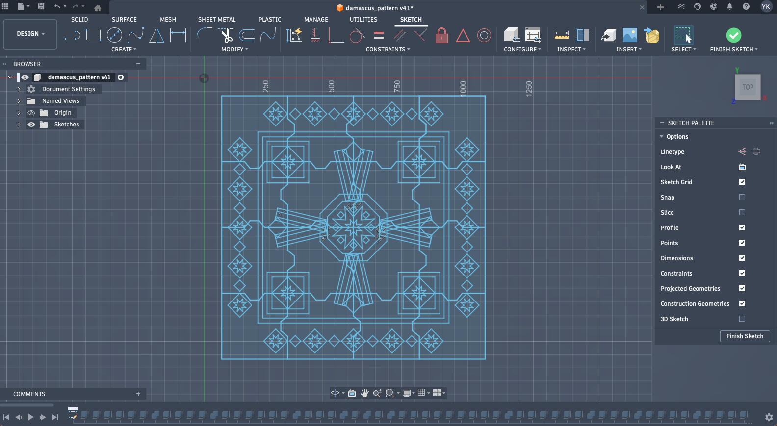
Creating a Fusion360 Design from the Generated SVG
The process started by importing the produced SVG into Fusion360 without the generated frame. Just a disclaimer, when I started this design, I was still learning the basics of the design, so in another scenario, I would have centered the design around the center of the XY-plane, created the components from SVG design extruded from the design, and significantly reduced the number of operations I made and edited elements in the timeline instead.
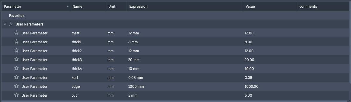
Next step, was to set up some parameters including different thicknesses for the thickness of our material, different elements of the design, parameters for the frame that I will design around the tiles, and kerf as measured during our group assignment.
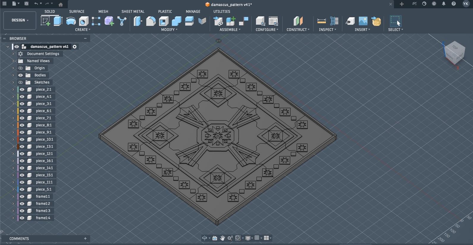
Then, I extruded each part of each pice into the piece's own component (it started initially by me creating new bodies instead of components, which was the wrong thing to do that I fixed later).
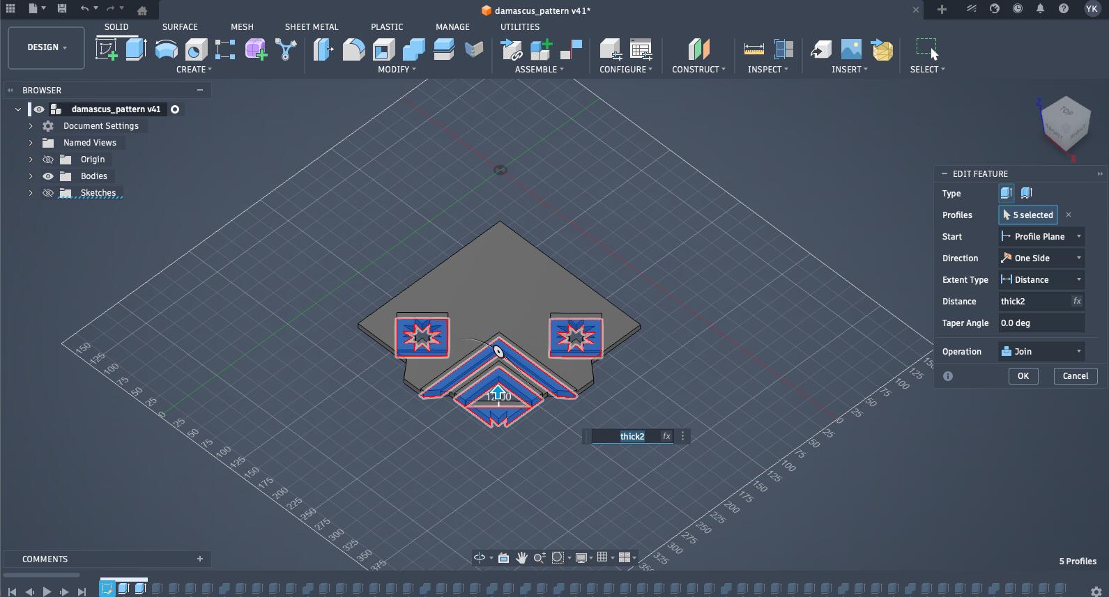
After the main design was fully extruded and each piece became its own component, here is how it looked.
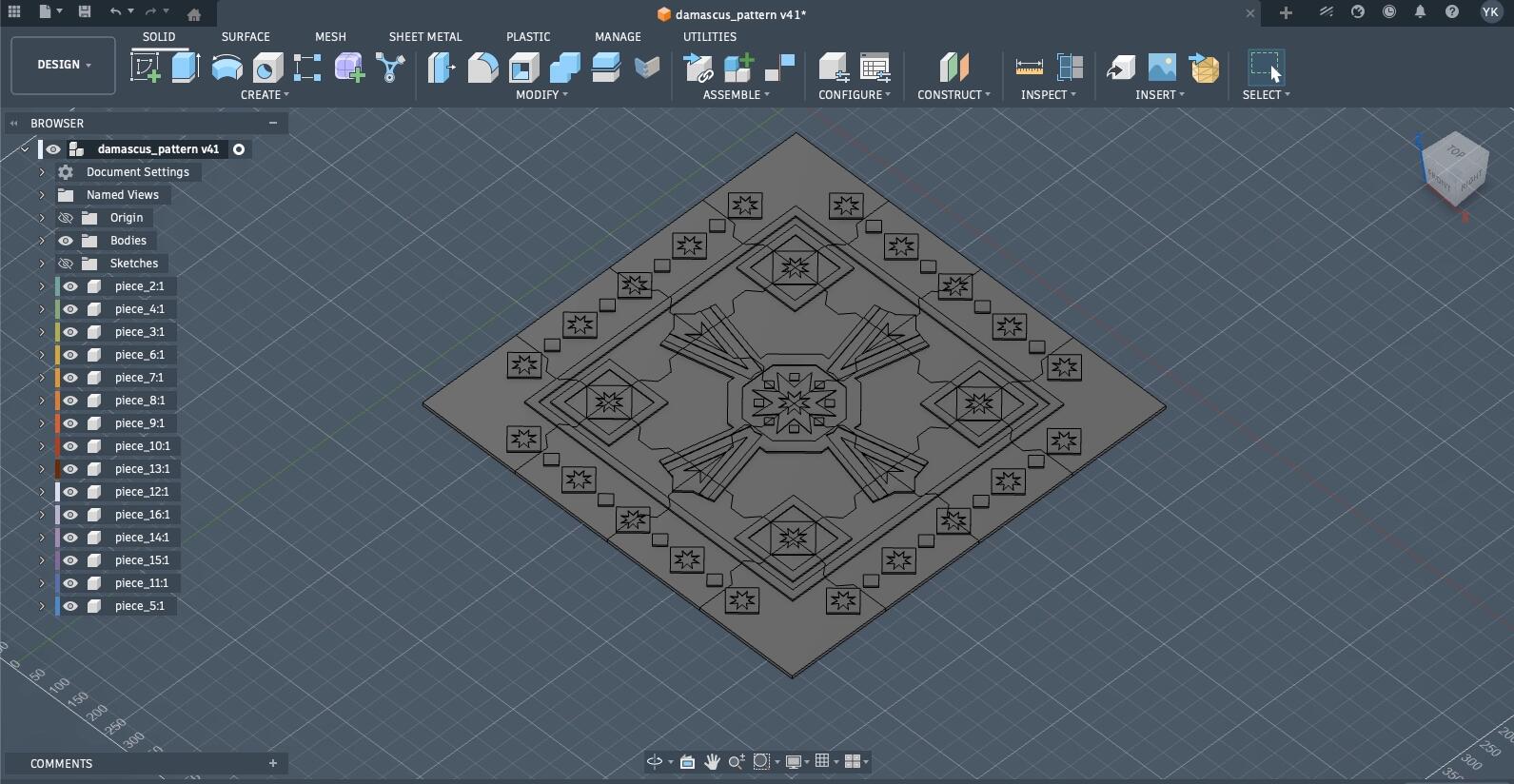
Then, came time to create the frame for this design where all those different puzzle pieces will be press-fitted together. This was how I initially imagined it to be like.
In the design, the full panel with the frame would be 1.1 * 1.1 m. It is a big design, to be honest, and Henk, my global evaluator mention that it wouldn't work if I created a smaller design to be able to carry it with me. Thus, I will be leaving it as a gift to FabLab Benfica.
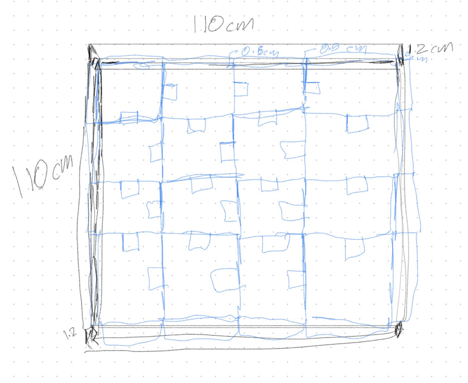
I started by creating a sketch of one side of my design, and defining it parametrically based on the materials thickness.
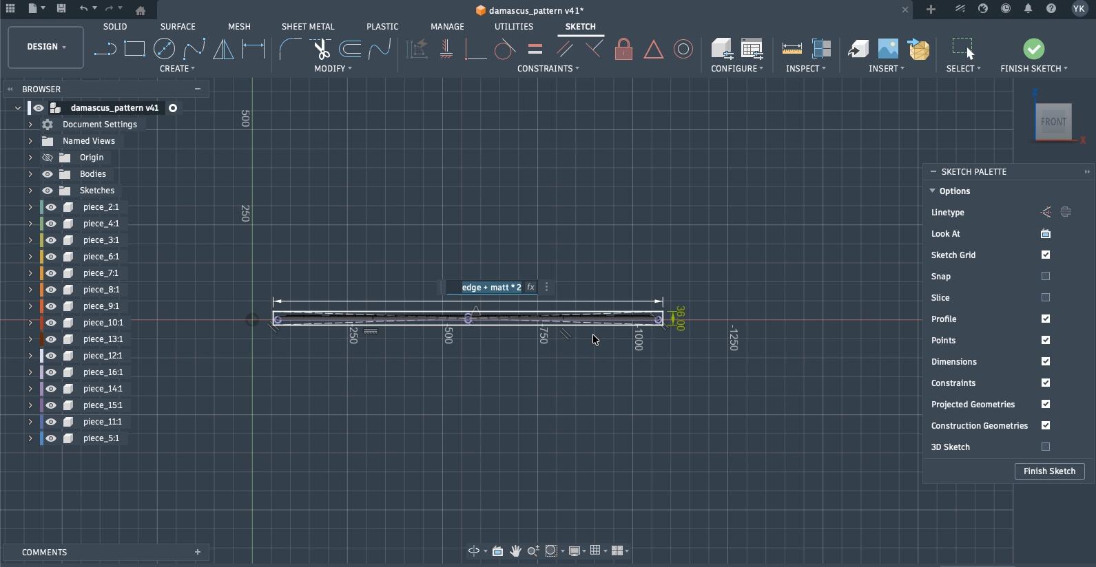
Then, I generated the rest of the sides after extruding that edge using the rectangle pattern tool.
Then, I rotated them accordingly, and turned off their connection momentarily till I rotated them all, so they will all be rotated to place without impacting each other.
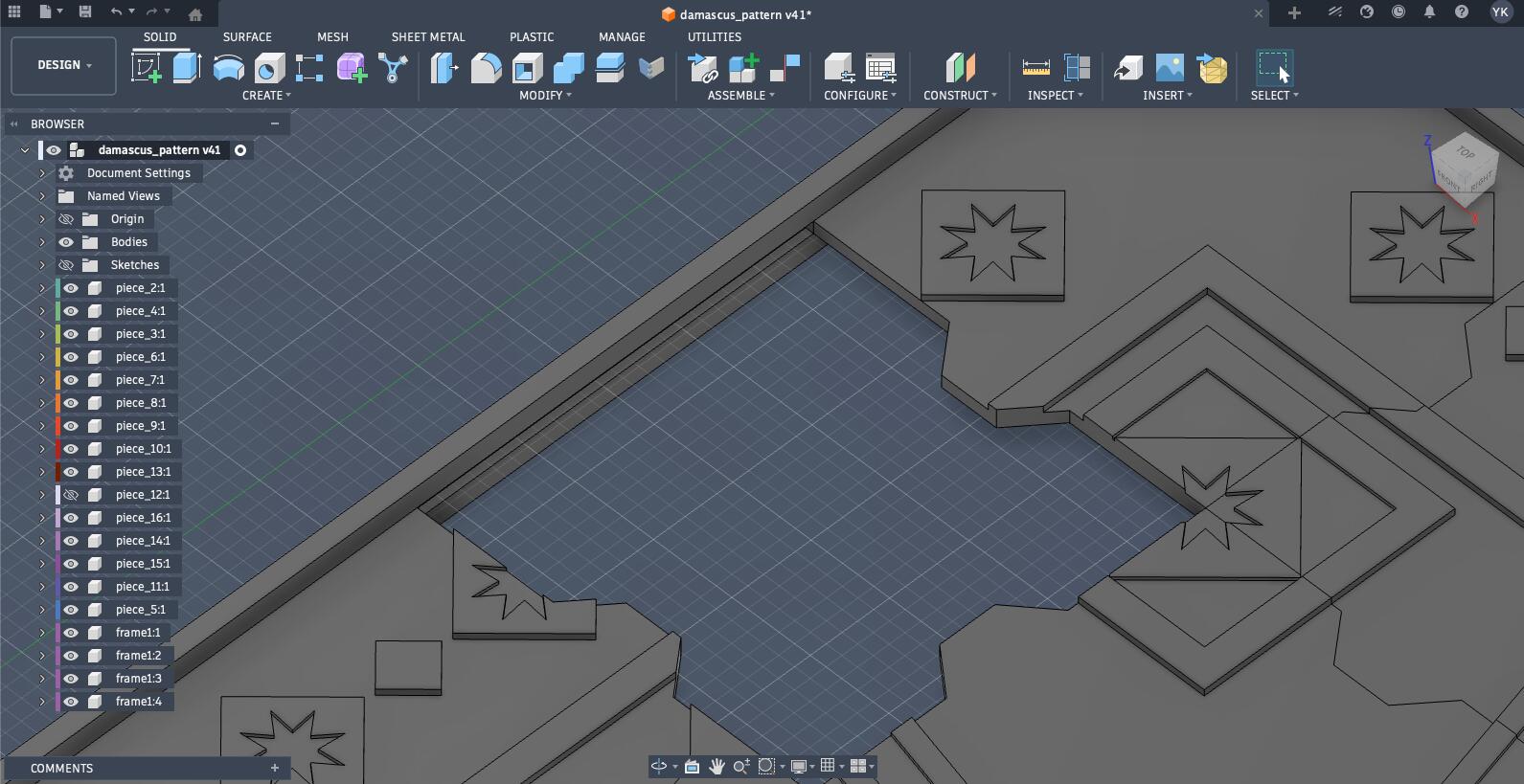
Then, I extruded each piece into the frame so the frame will be press-fitted to the pieces. The extrusion was with a specific parameter called cut.
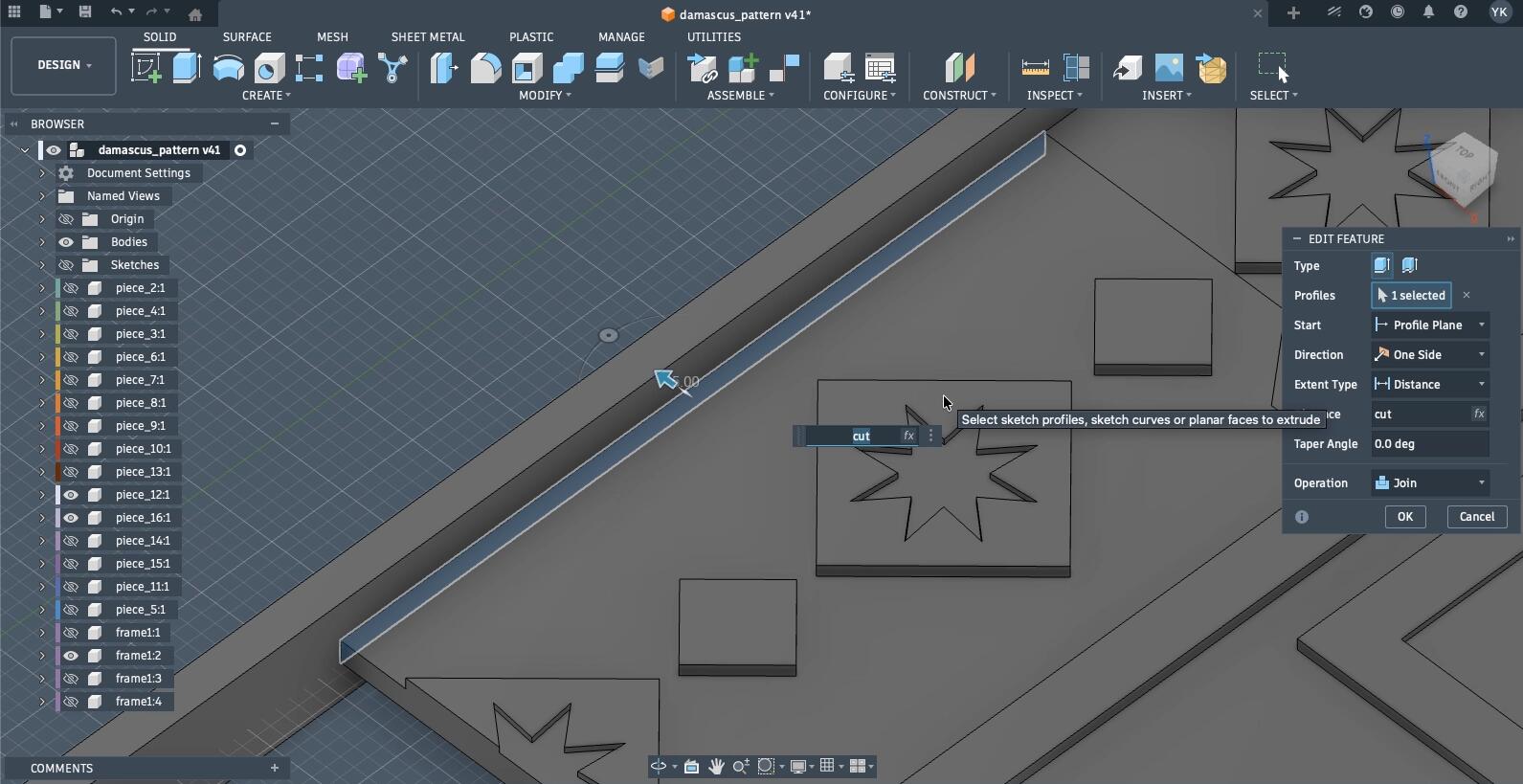
Then, I used each piece as a tool to cut into the frame making the press-fit work while also accounting for kerf where necessary. It isn't necessary everywhere since the force from the frame holding everything together will overcome the necessary kerf.
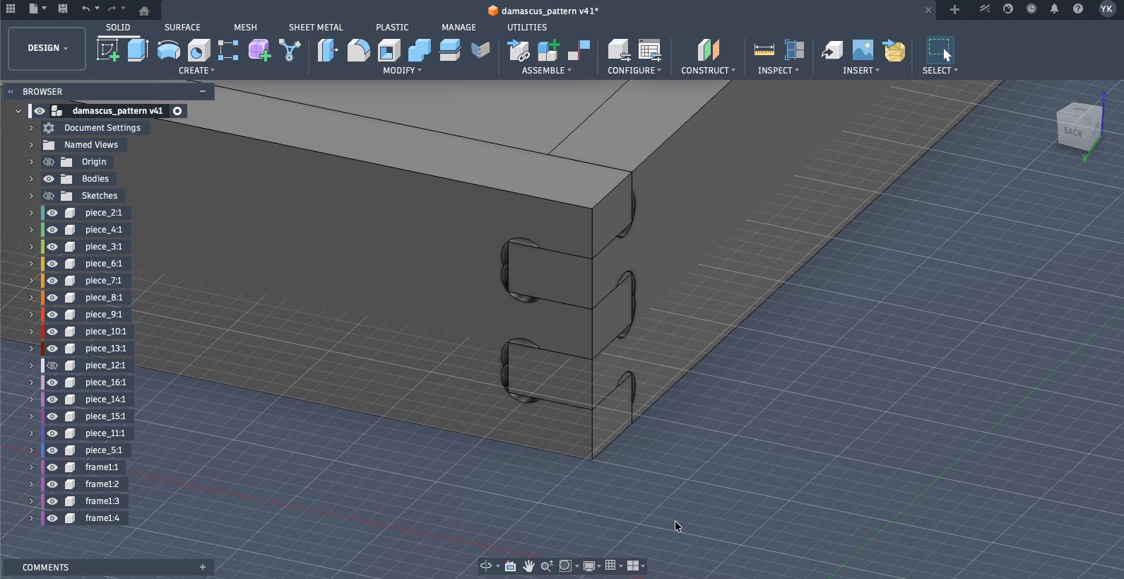
Then, I wanted to add the joints to connect each edge of the frame. Thus, I used a Fusion360 plugin called FingerJoints, which made the process of adding finger joints very simple.
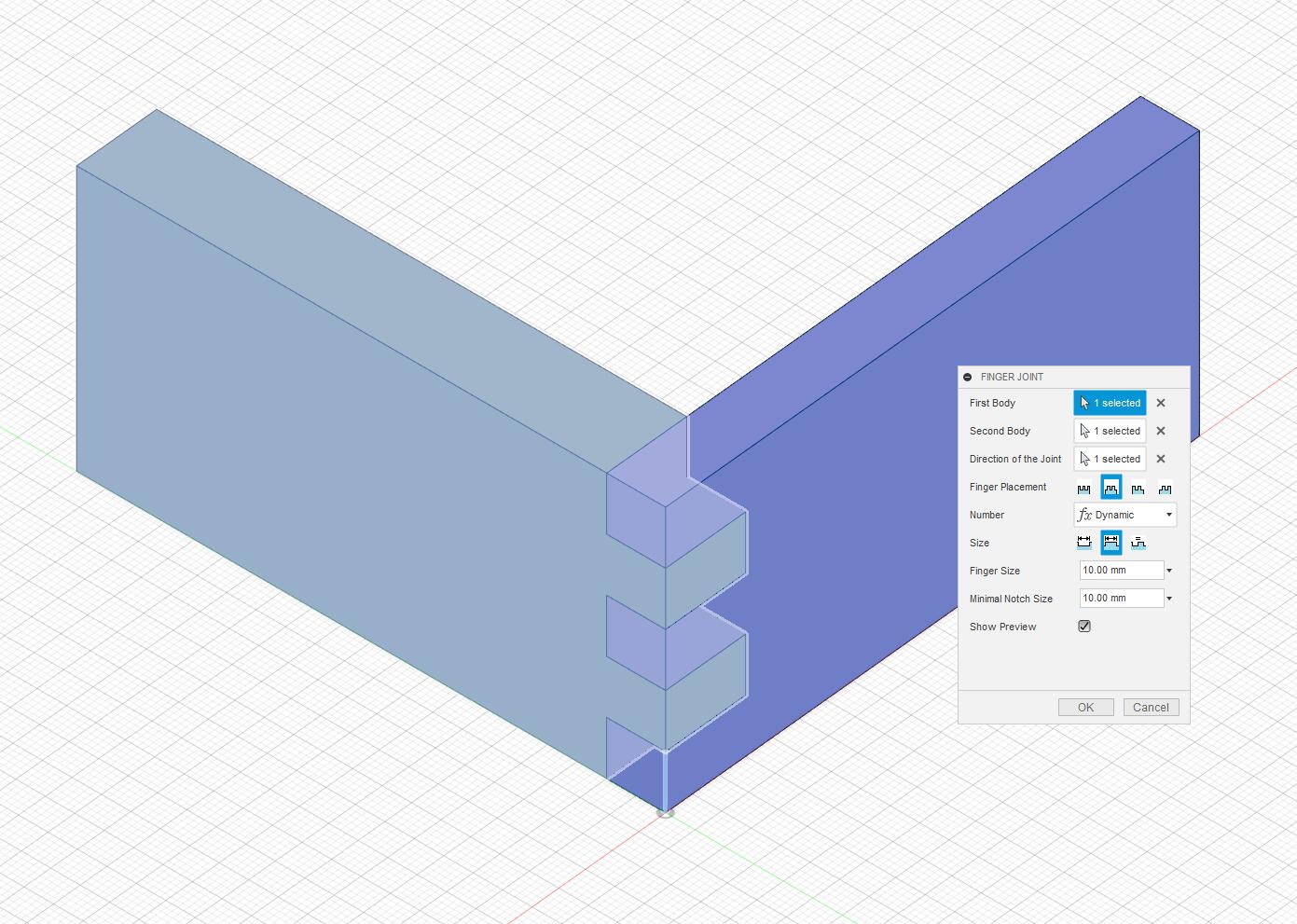
Additionally, I utilized the Nifty Dogbones plugin to account for the mills end when cutting those joints since a round end mill cannot cut a perfectly square inside corner, so it leaves a small radius that interferes with a mating square‑edged part.
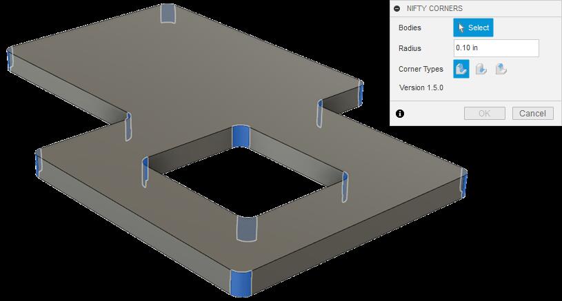
Since all the frame edges are part of one pattern, by doing this for one joint, it will be copied across the edges.
With that, the design was completed and I needed to move on to the CAM process preparing my design to be milled, but first, i will tell you about the second design i created, where I followed the right approach to designing in Fusion (not that there is a wrong one, but I needed to be more efficient and effective in it).
Designing a Replica of the Damascus Gate on Fusion360
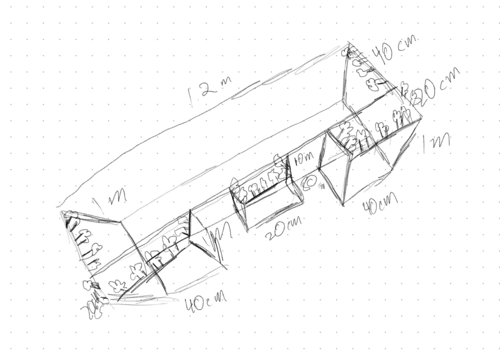
The other design I completed, but was a bit too big to milled for the week was a replica of the Damascus gate.

This was my initial sketch for this design.
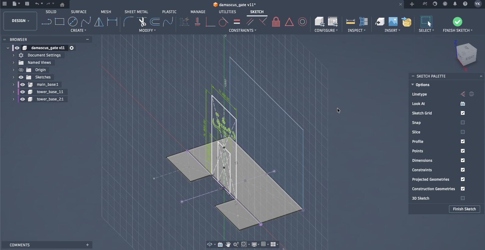
This had no AI involved in its design, so I got to work on Fusion 360. Thus, I created the base sketches, and ensured it is centered.
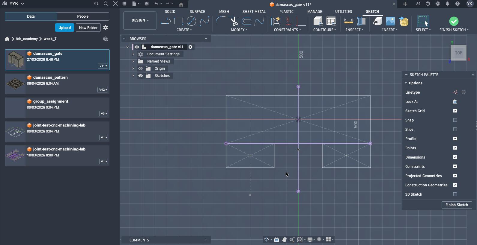
In addition, I set some parameters (in hindsight, some were unnecessary) that helped me out in the remainder of the designing process.

Additionally, I added sketches for different sides of the gate on different planes alongside an engraving having Damascus written on the main gate in Arabic.
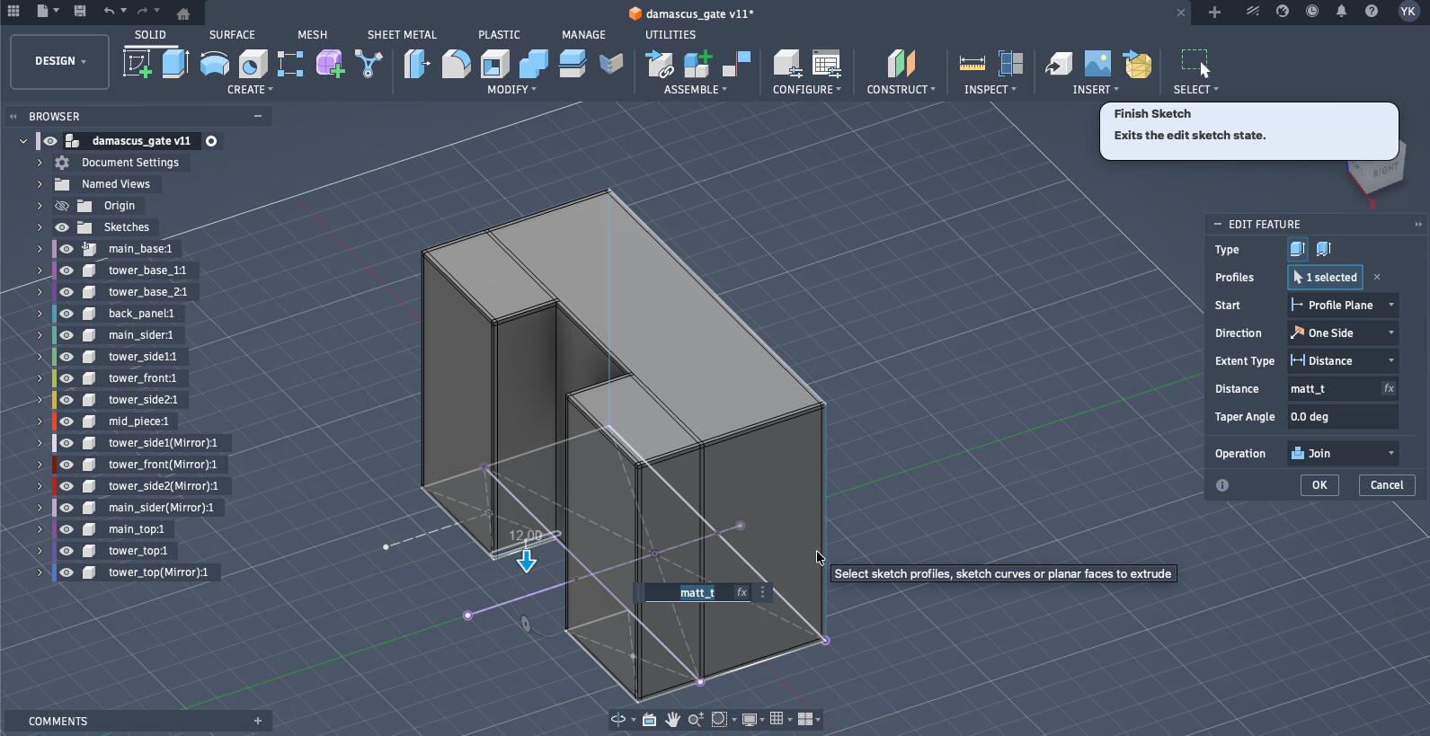
After extruding everything as its separate component, I extruded edges of each component that should be press-fitted together (each side that fitted together was overlapping which is needed for the next step). The thickness of each piece is the thickness of the material.
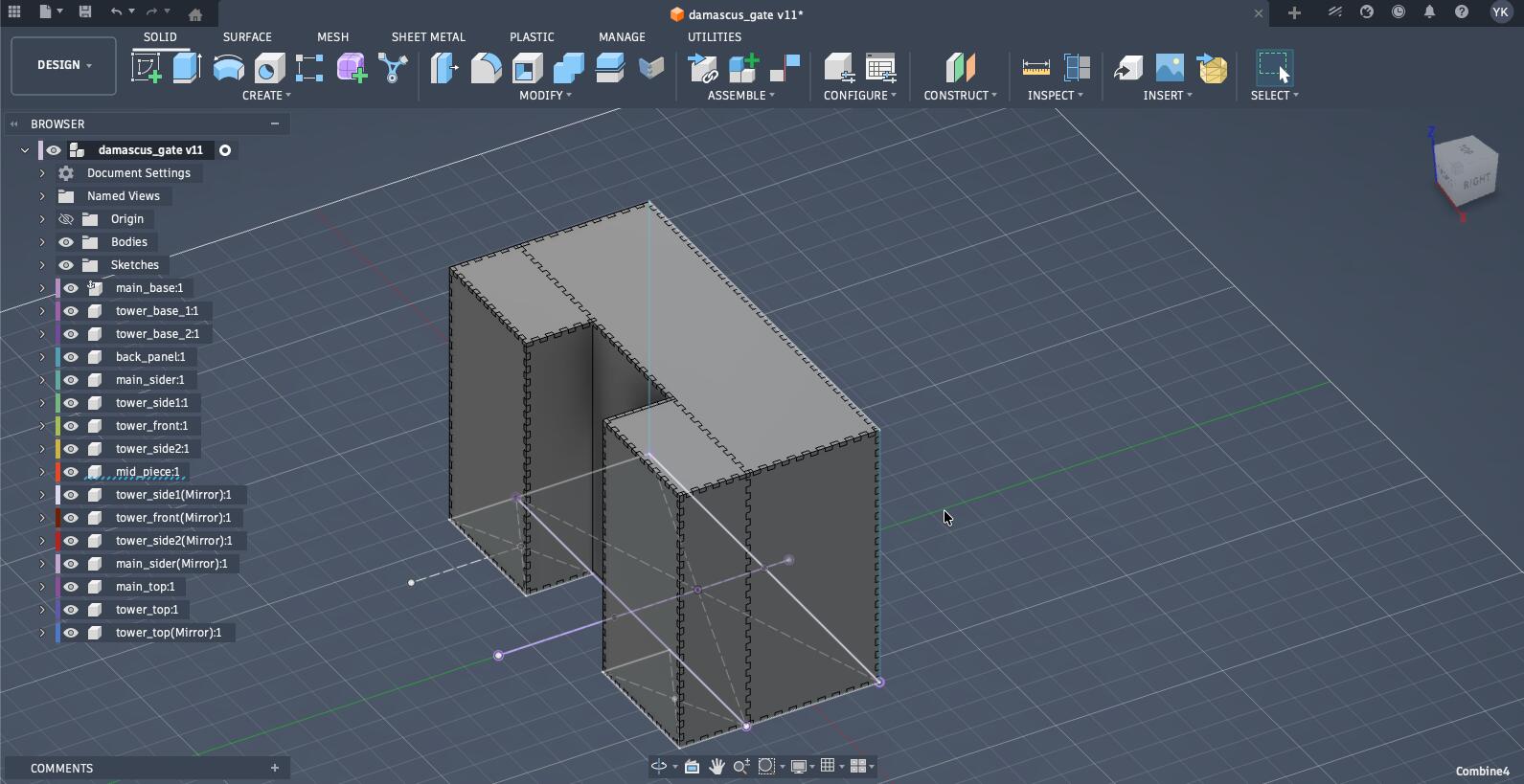
Then, utilizing the FingerJoints tool I described earlier, I made all the piece press-fit with each other.
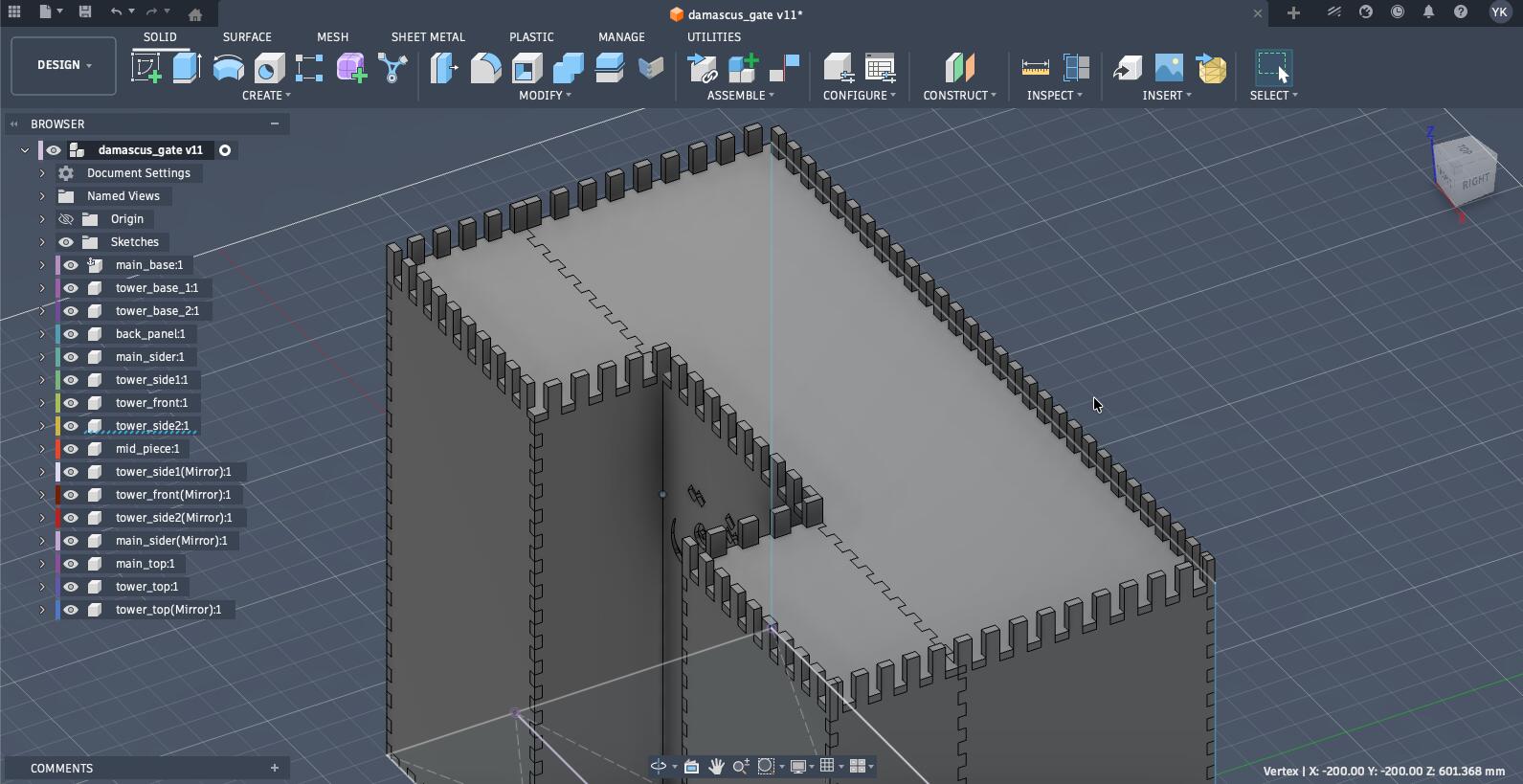
Using those made joints, I extended them to make the pattern at the top of the gate.
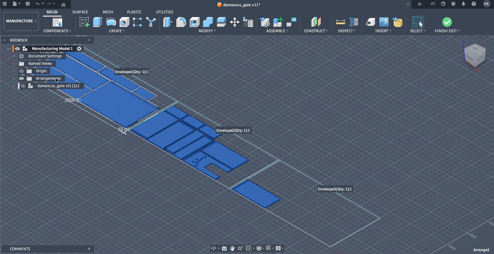
While arranging the pieces, I realized this was too big, too big. It needed 3 sheets of MDF, so while I finished the manufacturing CAM process on Fusion360, I didn't end up milling it.
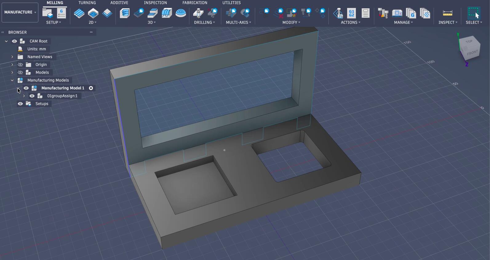
The Fusion360 CAM Process
The next step after completing the design was to generate a manufacturing model in the manufacturing mode in Fusion360, and arrange the pieces of the design to fit the piece of material I am using for this cut.
There are some details that I didn't go over here since they were very minimal.
(Fusion also highlighted the hidden original design before the arrangement)
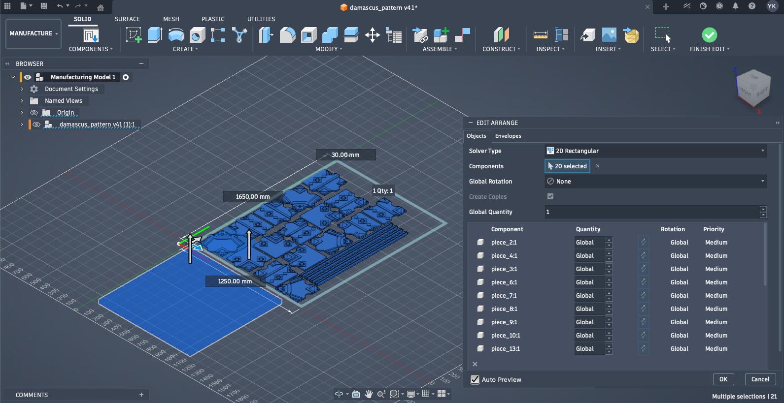
The piece of MDF I was using was 1.25 * 2.5 m big, but the area that was usable was only 1.25 * 1.65 m big, and in the envelope settings I created I set objet spacing to 20 mm quite a bit bigger than the mills diameter with it also having a 30 mm frame width to account for the placement of the clamps.
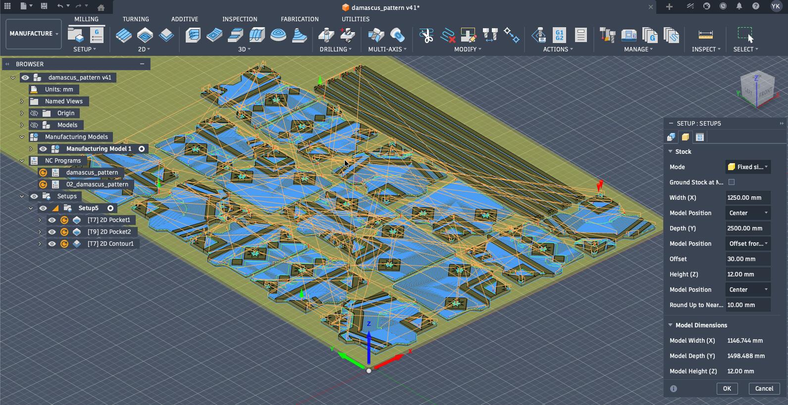
The next step was to create a setup alongside the operation on the manufacturing model. The setup's setting included choosing the axis of the material and setting up its size, and positioning our arranged model on the material.
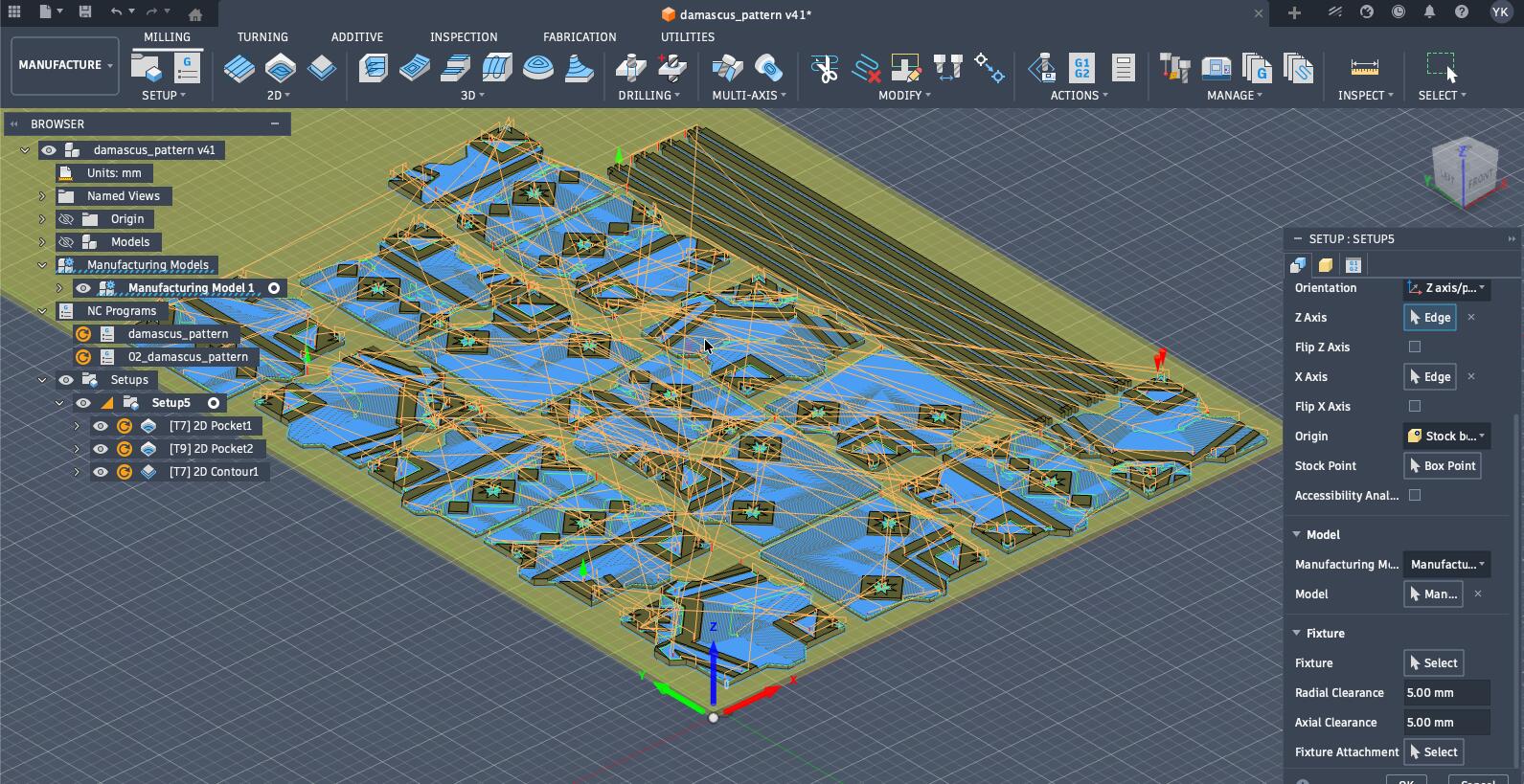
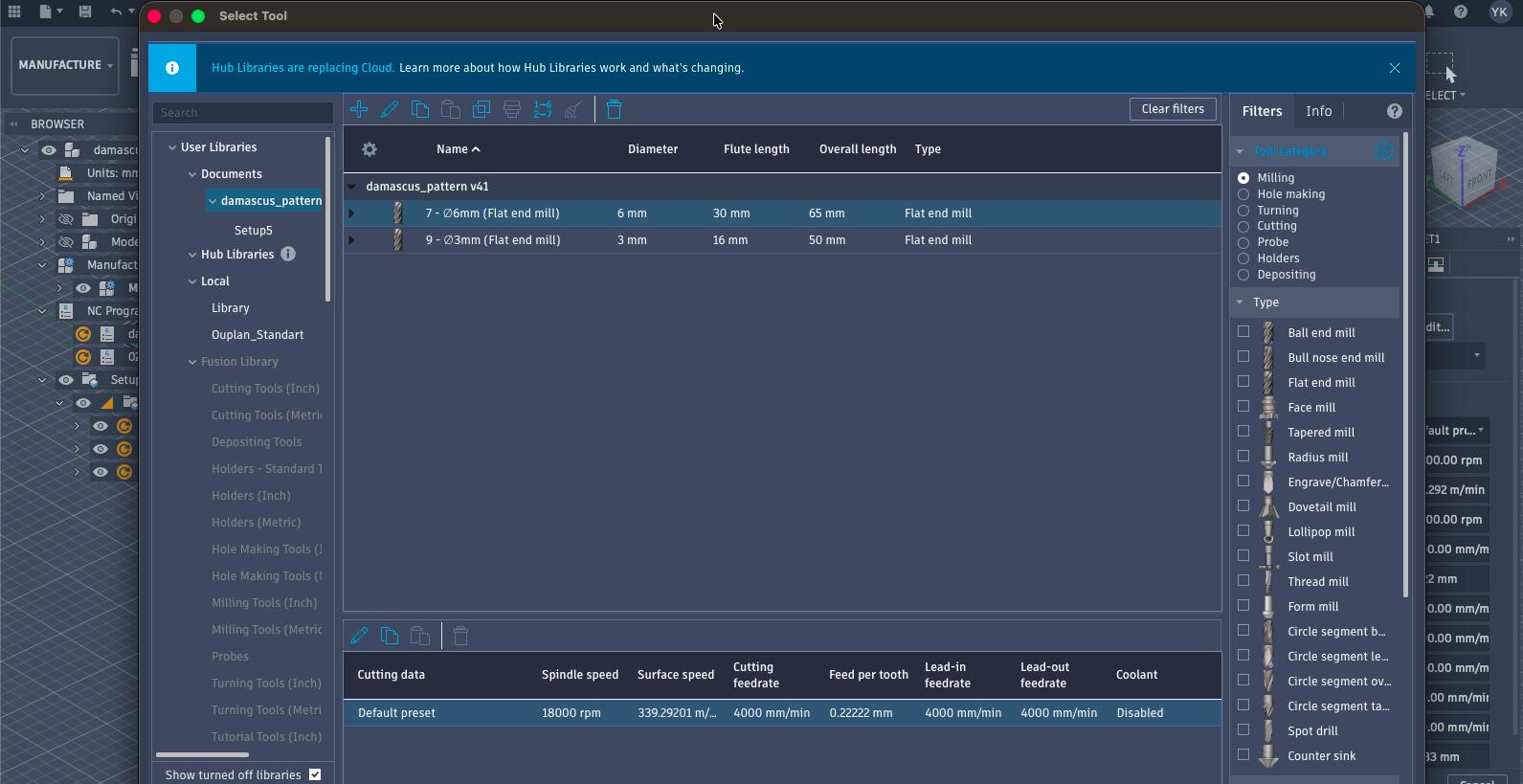
Now, it is time to set up our toolpath to include the different end mills that will be used. Thus, I imported the tool library and post-processor of our machine that Andre, my instructor, shared.
The plan was to cut everything using the 6 mm flat-end mill over everything and then utilize the 3 mm flat-end mill for the finer details, of course, I started with 2D pockets and then the 2D contours.
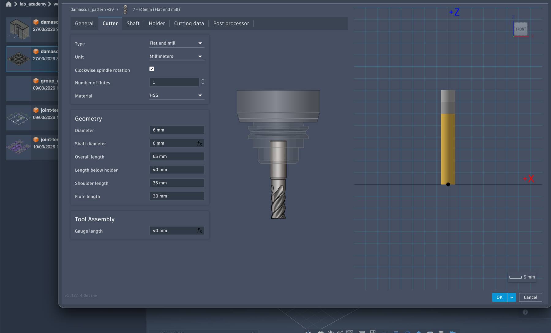
After importing the library Andre shared, I needed to edit and verify the settings of each tool. The base Ouplan library had the standard tool slots, but my job library needed the actual tools I was using: a 6 mm flat end mill for the main milling and a 3 mm flat end mill for the smaller details.
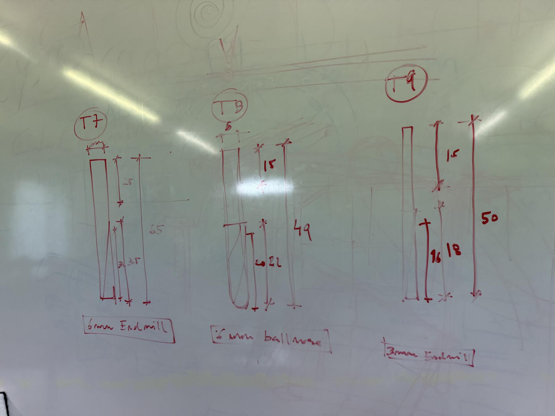
Here are the settings for the tools I used:
| Setting | Tool 7 — 6 mm Flat End Mill | Tool 9 — 3 mm Flat End Mill |
|---|---|---|
| Material | MDF | MDF |
| Tool type | Flat end mill | Flat end mill |
| Tool number | 7 | 9 |
| Diameter | 6 mm | 3 mm |
| Number of flutes | 1 | 1 |
| Spindle speed | 18,000 rpm | 18,000 rpm |
| Cutting feedrate | 4,000 mm/min | 4,000 mm/min |
| Plunge feedrate | 600 mm/min | 600 mm/min |
| Stepover | 2.4 mm | 2.4 mm |
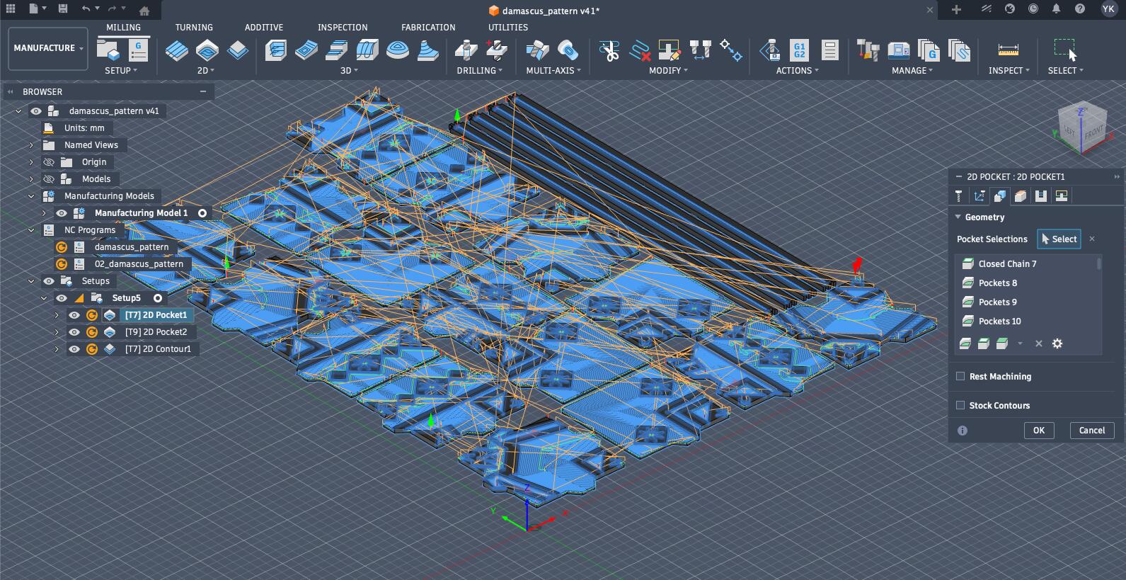
The first operation was to 2D pocket everything with the 6 mm tool, and to ensure that the cut is clean I needed to set it to cut at multiple depths so it would cut gradually. While most elements were chosen properly by selecting them as pockets, some elements needed to be selected as closed chains to be cut properly.
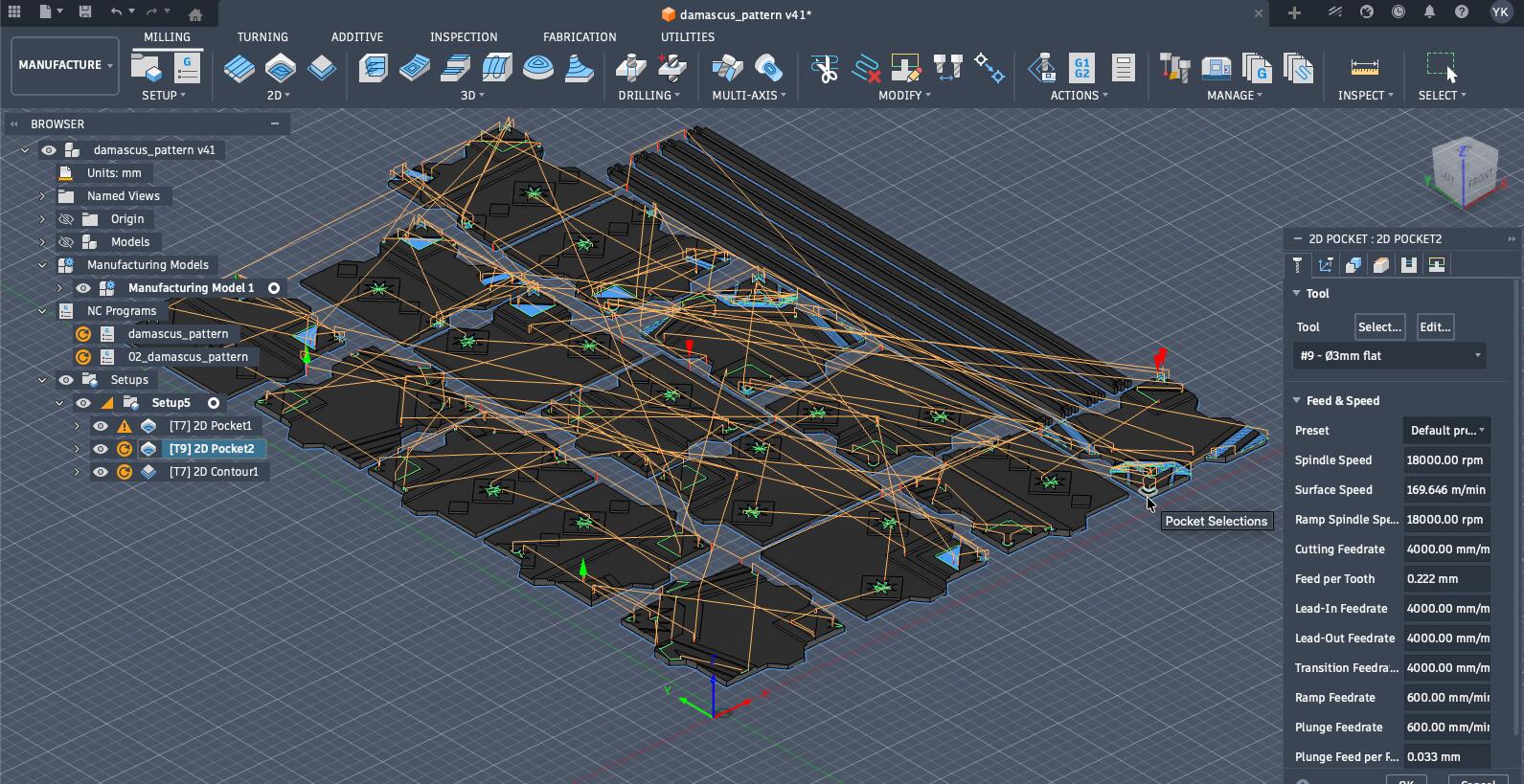
I repeated the same process for the elements that needed finer details like the stars but with a 3 mm tool.
The final step was doing the 2D contours, which needed accuracy in choosing the correct edges for the tool path. Additionally, I needed to add tabs so each piece is held in place while the other pieces are cut.
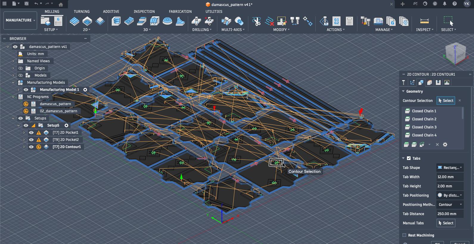
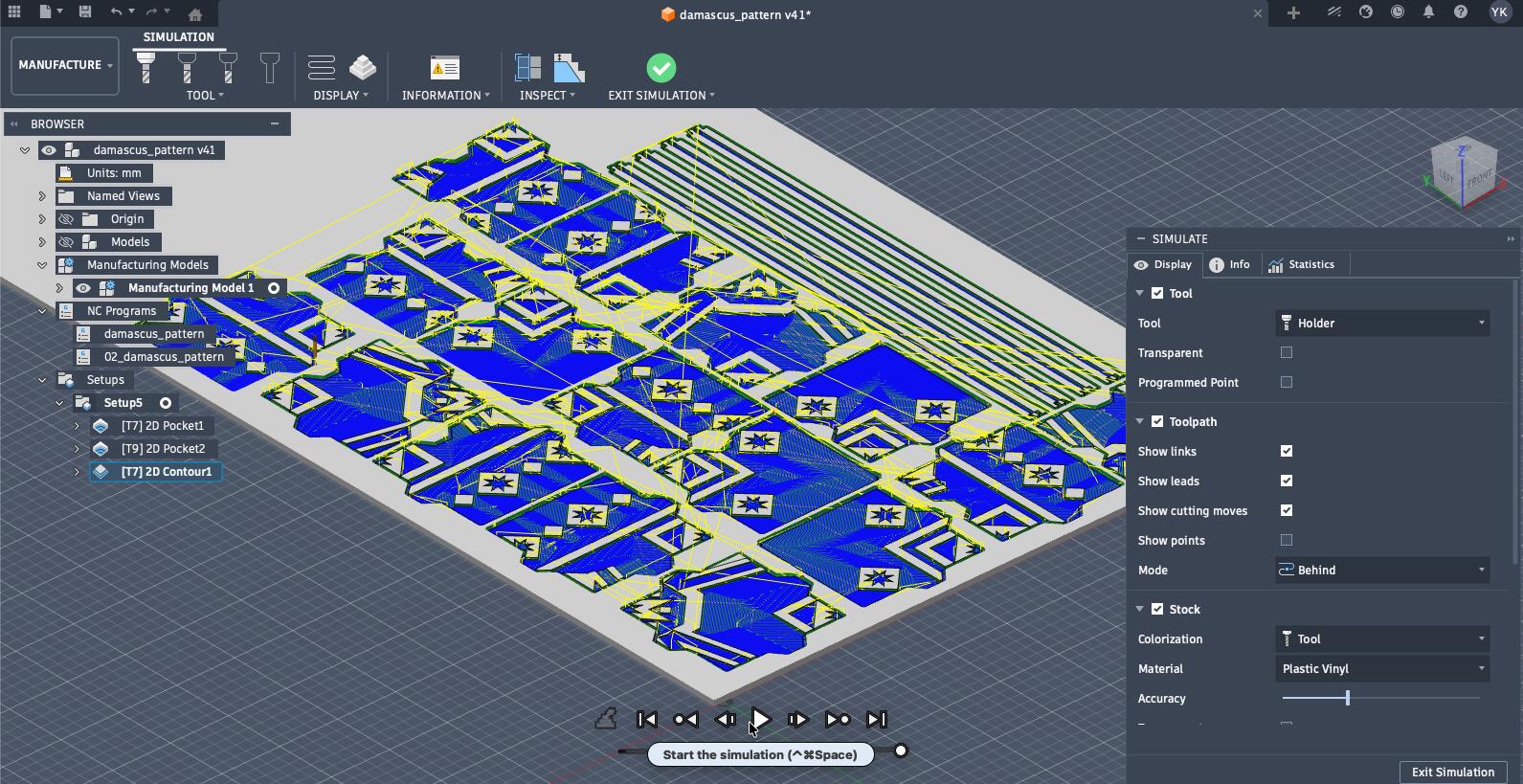
The next step is to simulate the process to ensure everything works well.
Then, I "exported" the cut using the post-processor shared with us from the Ouplan manufacturers.
The post-processor trasnlates the generic toolpath data from Fusion 360 into a specific kind of G‑code or NC program that the CNC machine can understand.
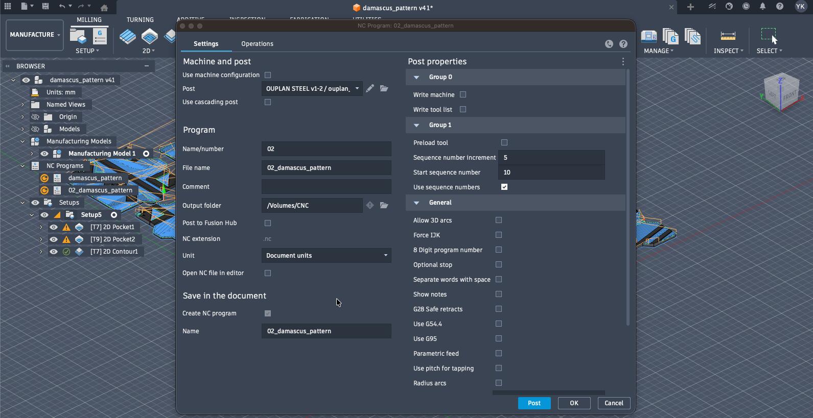
Milling Something BIG
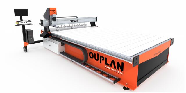
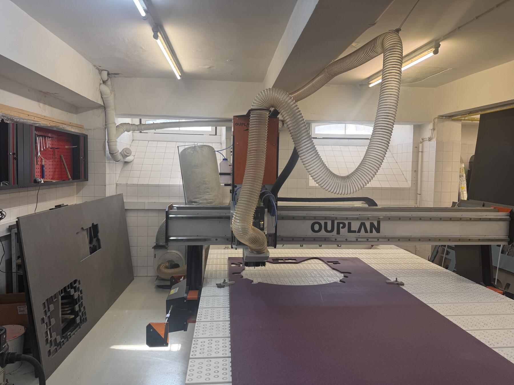
Now, here's how I actually milled the Damascus mosaic tiles and its frame. We faced a couple of issues at the start. As described in my group assignment, I will be using the Ouplan Steel 3020.
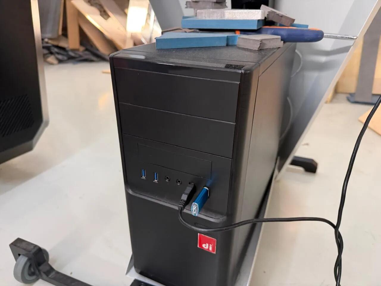
The process starts by putting the exported folder into a USB drive plugged in into Ouplan's computer.
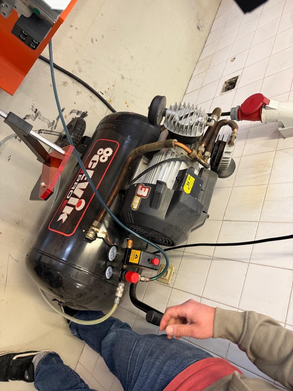
After turning on the machine, I needed to turn on the machine's air compressor (that had a problem that I'll describe later).
Setting Up the Machine: Manual and Jog Modes
Once the air pressure was stable, the next step was setting the work origin. This is the part where "Manual" and "Jog" modes matter.
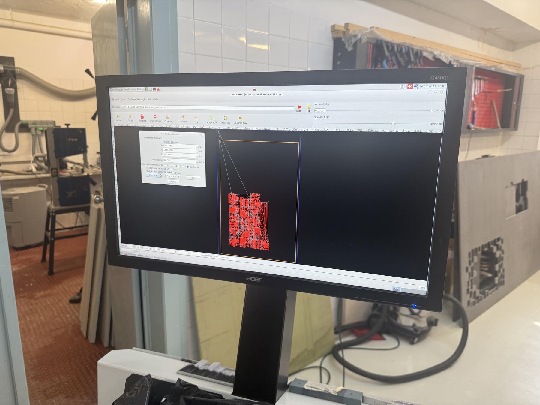
In InoControl, I first opened the exported .nc file from the USB drive. Then I sent the machine to its machine origin using the Origin button, so the controller knew where the machine was before I defined my work zero.
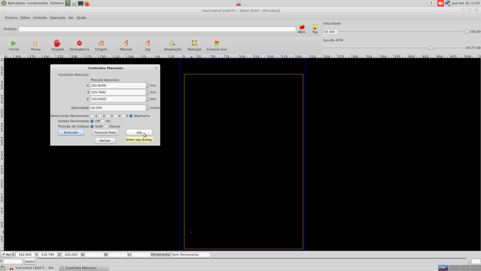
For rough positioning, I used Manual mode. Manual mode lets you move the head more coarsely by entering positions or moving toward a selected area on the bed. I used it only to bring the tool close to the stock, not to touch the material.
Then I entered Jog mode for the fine positioning. In Jog mode, I could move X and Y with the arrow controls, and move Z up and down separately. The controller also lets you choose step size, like free movement, 0.01 mm, 0.1 mm, or 1 mm. I used bigger moves while the tool was far away, then smaller moves once I was near the stock corner.
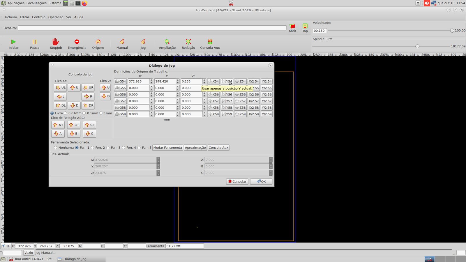
After the tool was above the corner of my stock, I set the G54 work origin for X and Y in the Jog dialog. For this job, Z was based on the machine/table setup and the material thickness defined in CAM, so the important repeated step was setting X and Y correctly for the actual sheet position. If the stock thickness changed, the CAM setup and Z reference would need to match that.
FabLab Benfica has this page that guides users of the lab on how to operate the CNC machine.
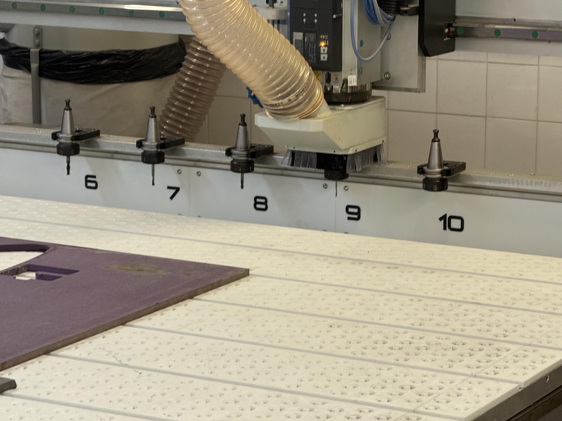
Here is the physical tool position near the stock while we were setting up the job:
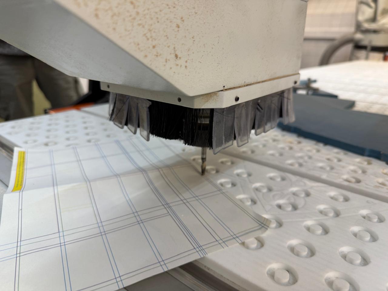
First Few Attempts at Milling and Issues with the CNC
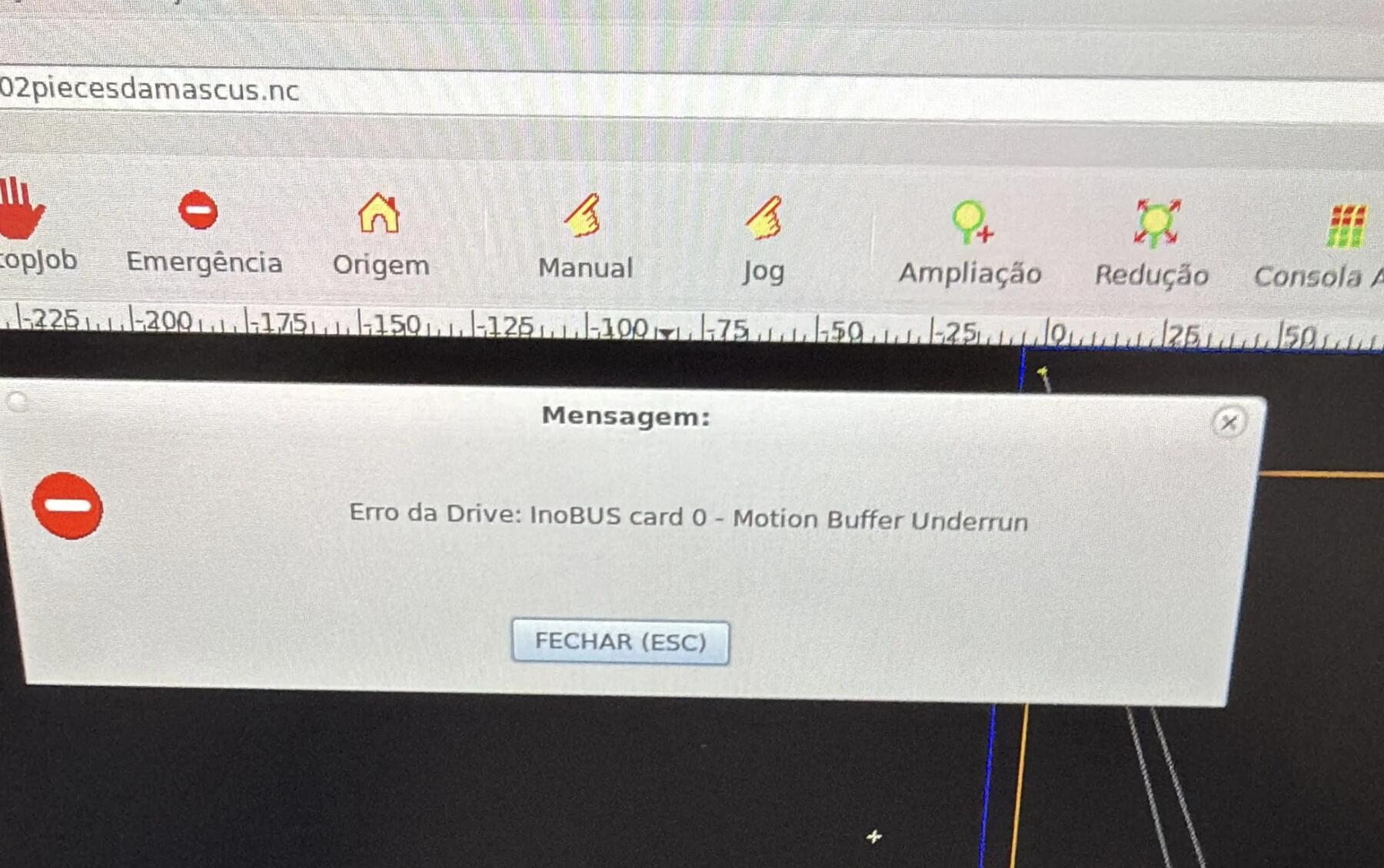
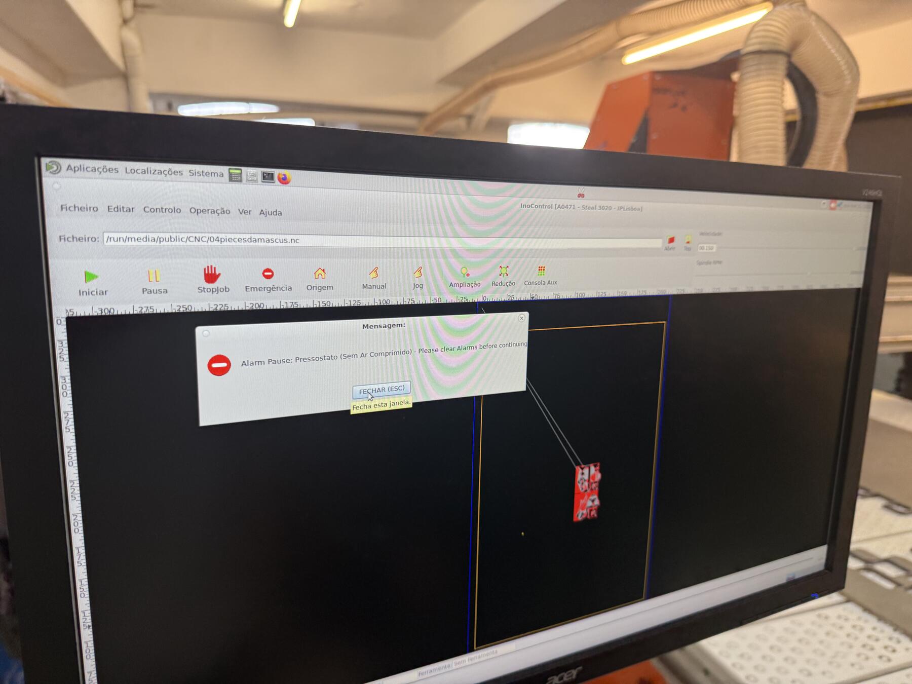
As I started my first cut, we realized that the compressor had a leak, which kept the machine to stop every 5 minutes as it cuts, and what was worst is that as I go to turn the compressor back on manually, it overheats, making it almost impossible to cut this on time.
Thats why I chose to start with only 2 pieces :)
Still, I wanted to get something done, so I stuck with it and did that very long, tiring manual process, but it still didn't work out.
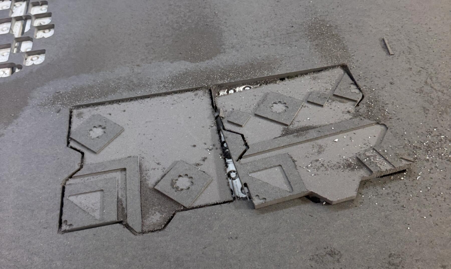
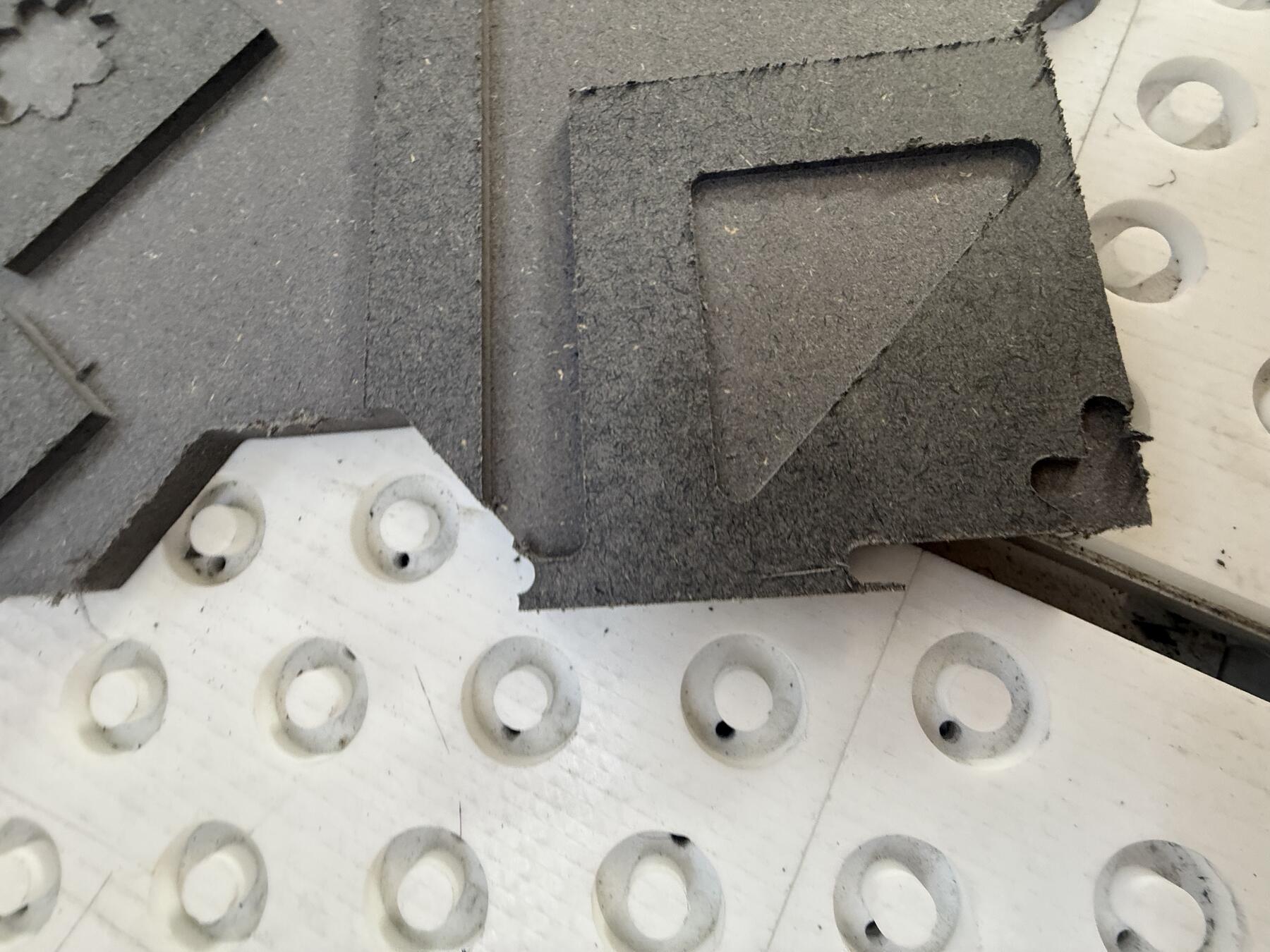
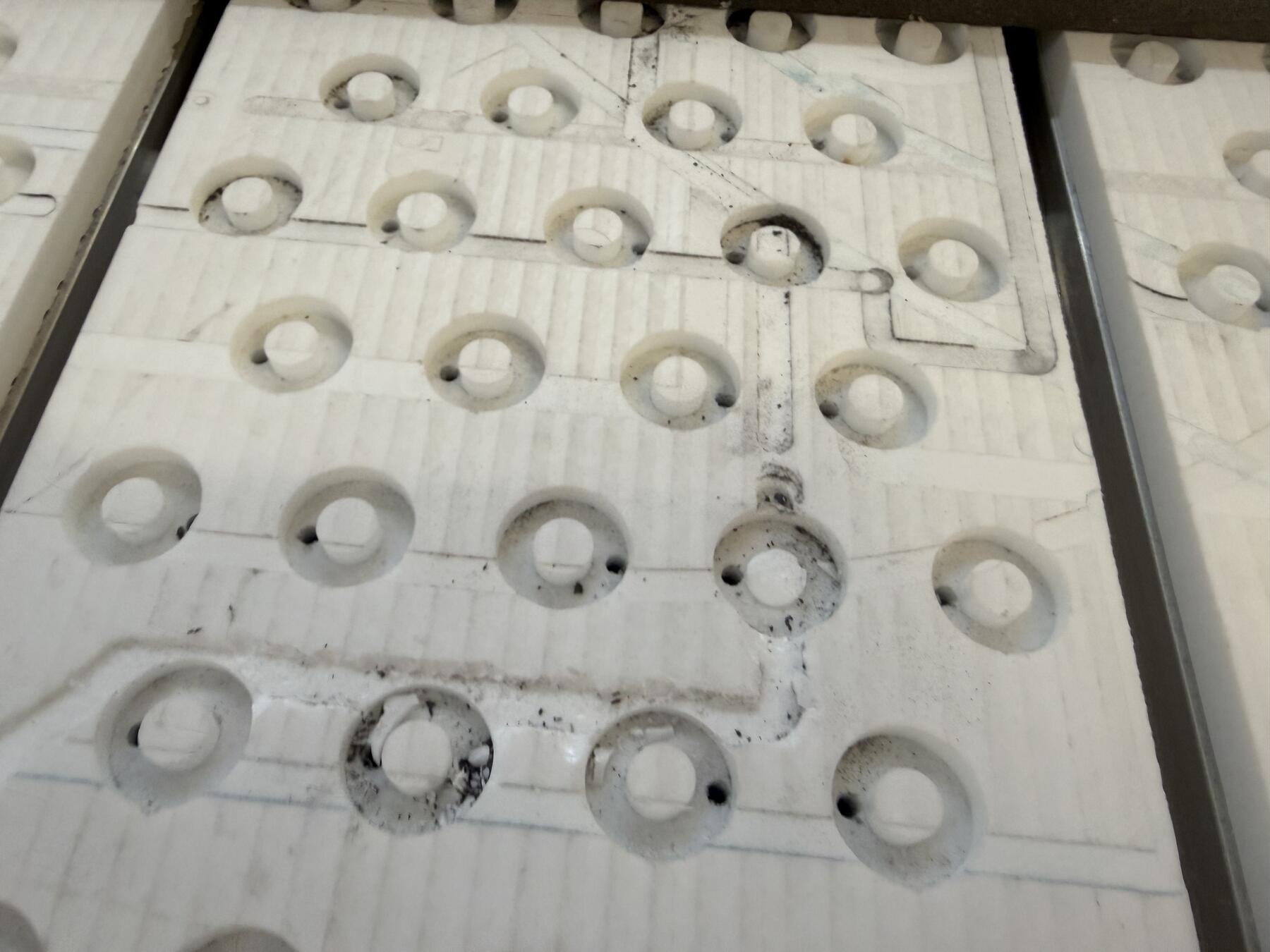
As you can see there is some white debris, which seems to be from the CNC's table, and the second piece wasn't cut properly.
That leads us to realizing that as the mill was cutting, it broke off, there could've been multiple possible issues like the spindle not being held properly and sliding down or was an issue in our CAM settings of not cutting through multiple depths (this was fixed in the walkthrough I had above).
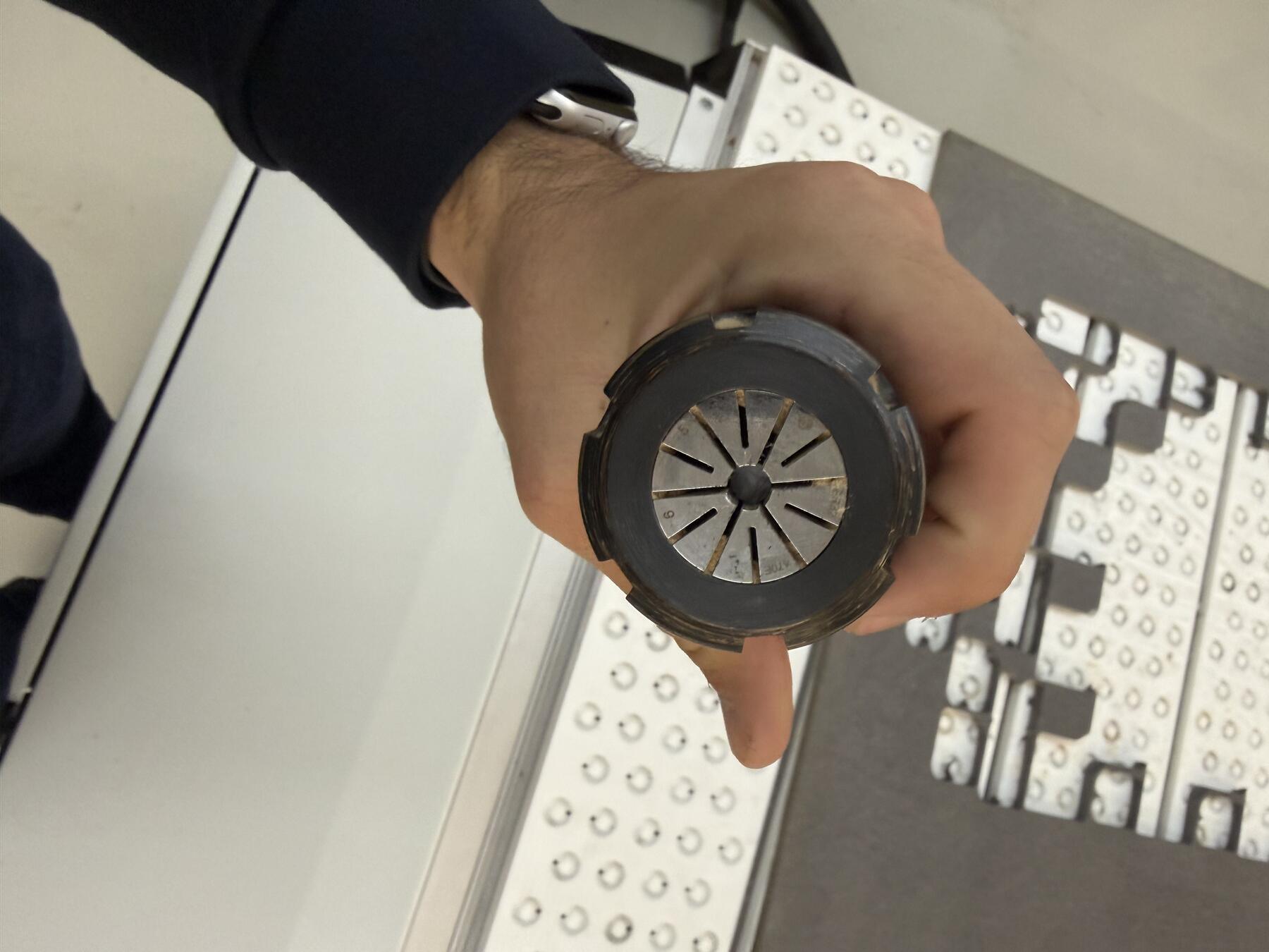
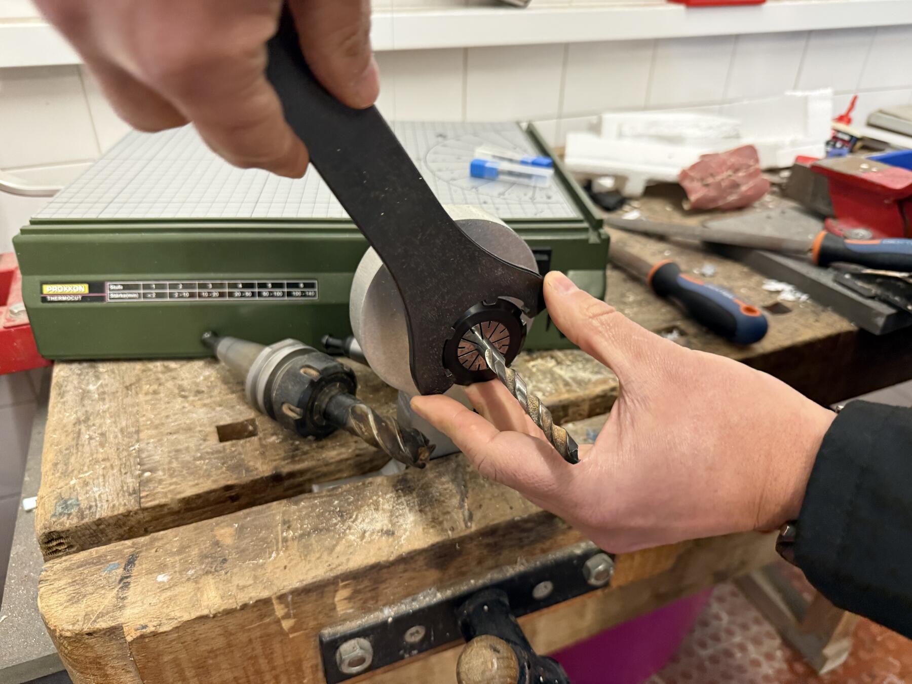
Then, working with Andre, we added mills to all the tools on the CNC since some were broken from before. Andre walked me through it. Using a wrench, we would take out the old mill and put in the new one.
The Successful Attempt :)
While I wanted to make the old compressor work, it wasn't sustainable for such a big cut. Ricardo had a compressor from his family's farm that he brought to the lab replacing the older, leaky one.
I fixtured the material using clamps.

Next step was to put the full exported file into machine and zero out the x and y.
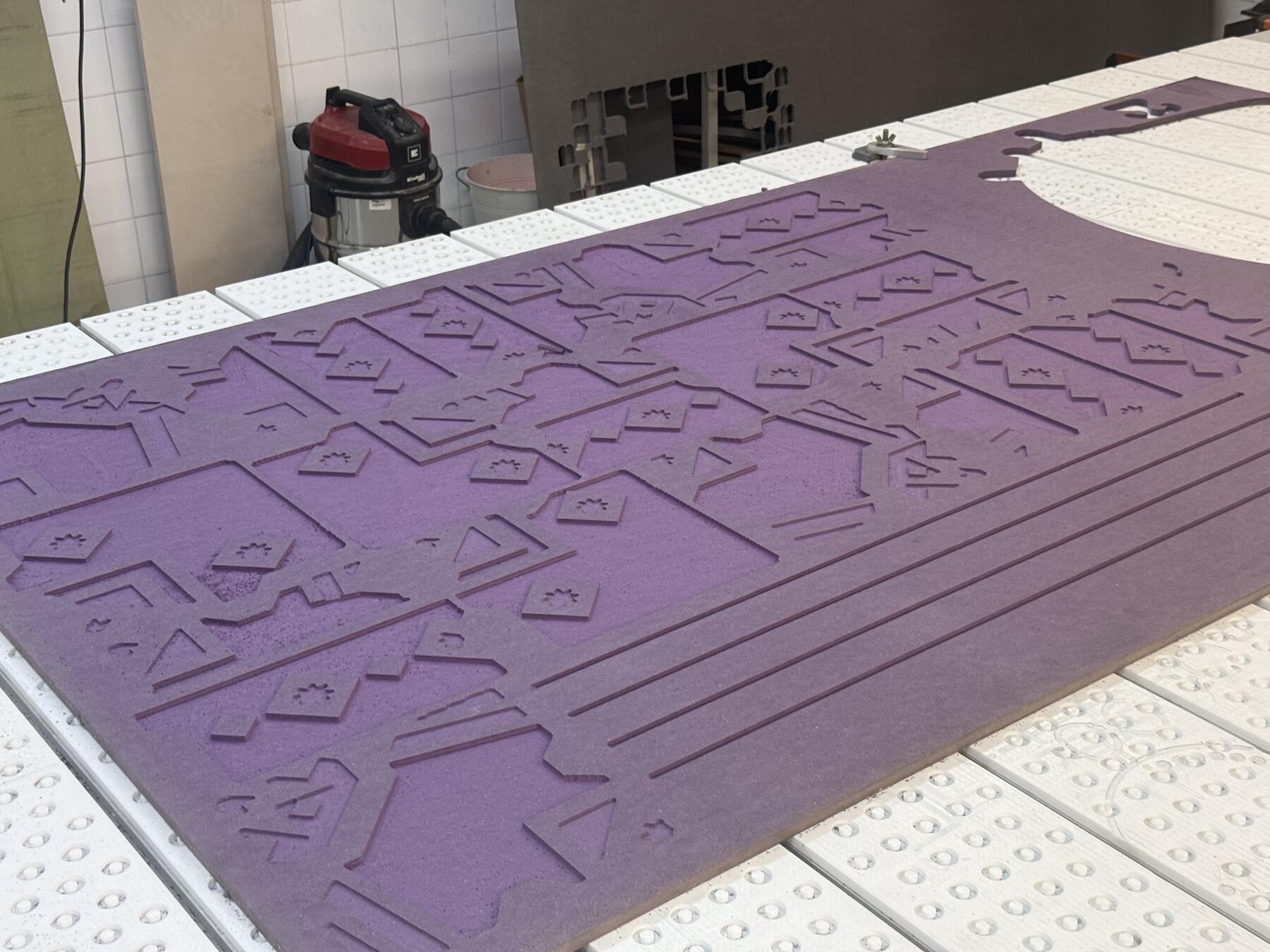
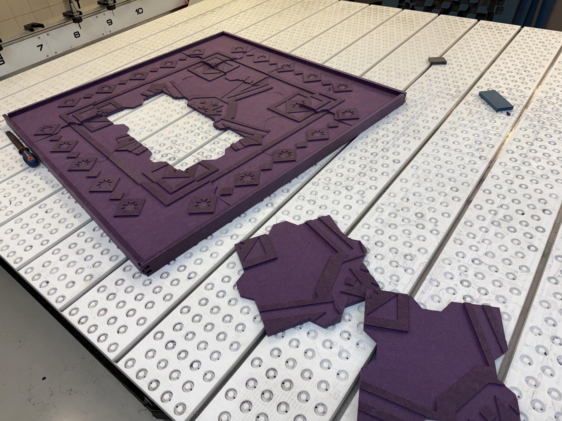
I send the job to the CNC, and about 3-4 hours later, the cut was completed correctly. Of course, throughout the cut, I stayed close and kept my ears open for any weird noises coming from the cutter.

Post-Processing and Assembly
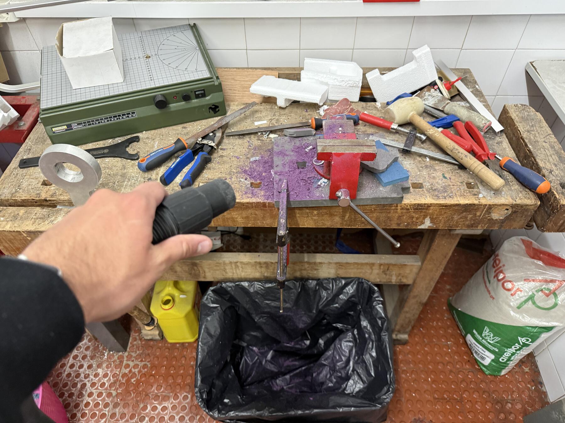
Then, it was time to start finishing the cut since it had some small remaining artifacts from the cut and I needed to remove the tabs I added to it.
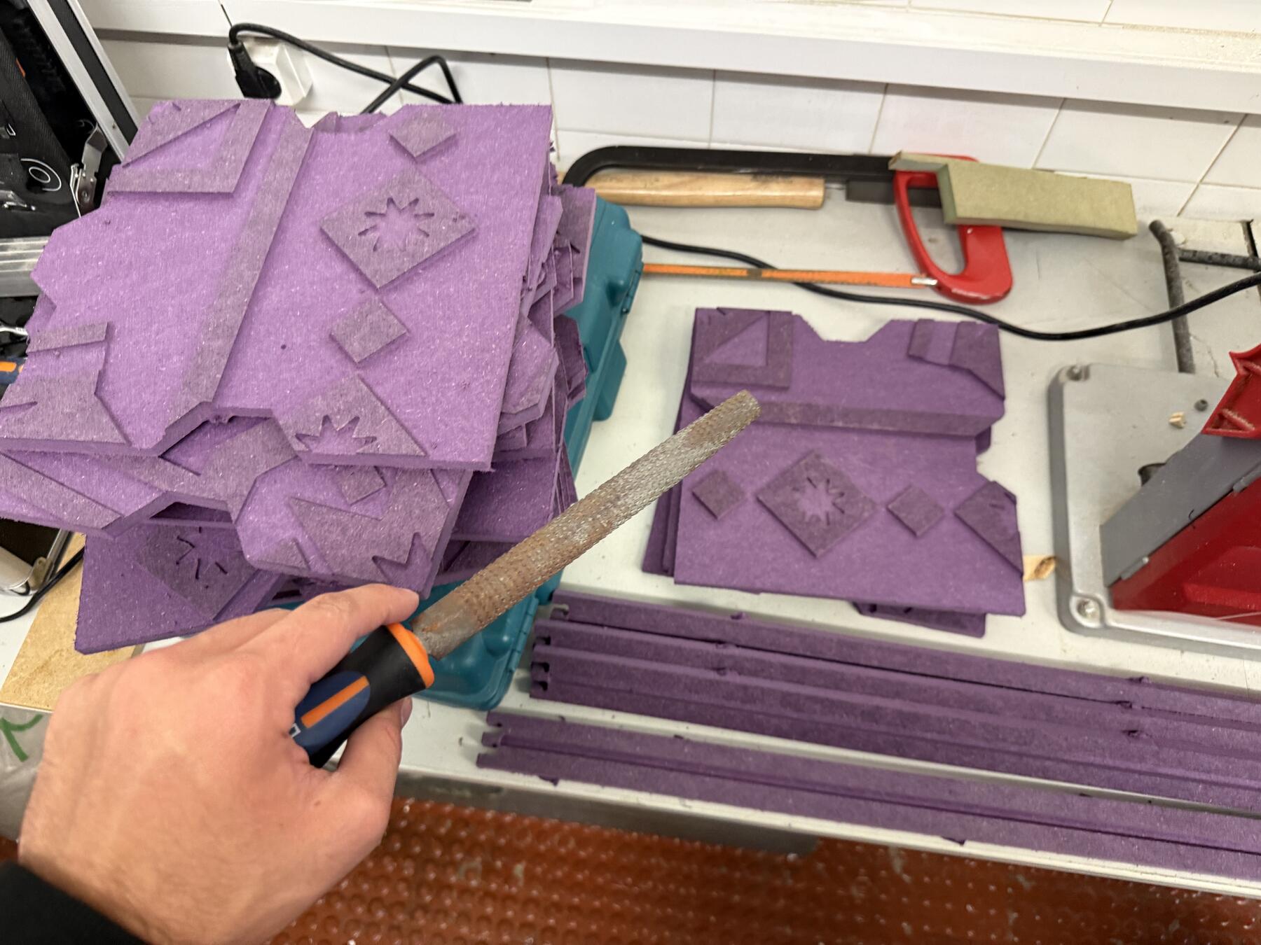
That caused quite a mess that needed to be cleaned. Always follow the rule of keeping your workspace cleaner than you found it, so the vacuum cleaner is your best friend here.
While I was press-fitting it, I realized that the material I used wasn't uniform in height since the material absorbed some humidity making it thicker at some places, which made press-fitting it a bit hard.
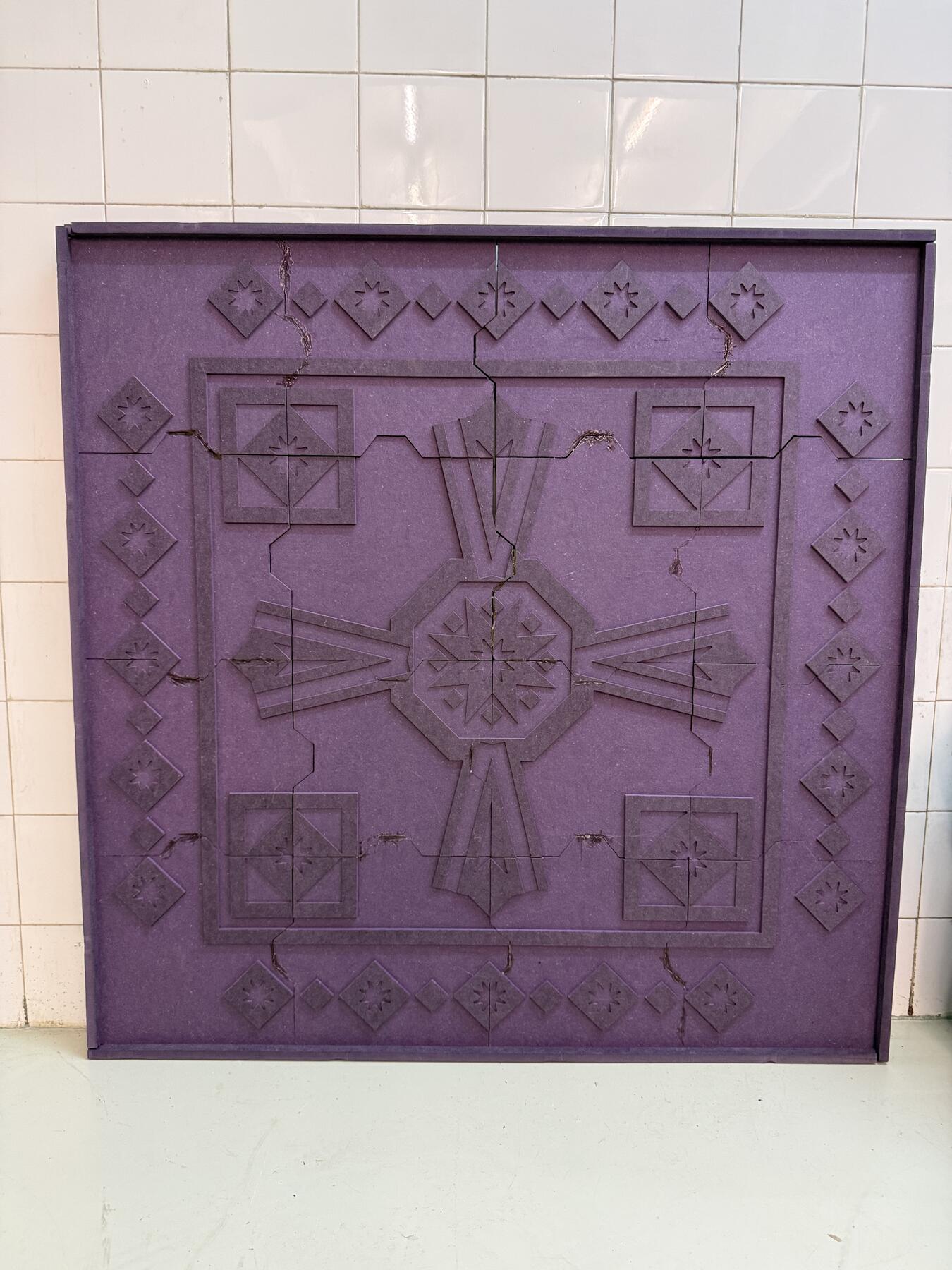
Final Result
Here's the mosaic tiles frame completed:
Original Design Files
- Python script to generate the SVG
- Full design SVG
- Mosaic tiles 3D file (.step)
- Damascus gate 3D file (.step)
This Week's Checklist
- Linked to the group assignment page
- Reflected on your individual page what you learned of your labs safety training
- Documented how you designed your object and made your CAM-toolpath
- Documented how you milled and assembled your final product (including setting up the machine, fixturing, feeds, speeds etc.)
- Described problems and how you fixed them
- Included your design files and 'hero shot' of your final product