
Week 16
Week 16: System Integration
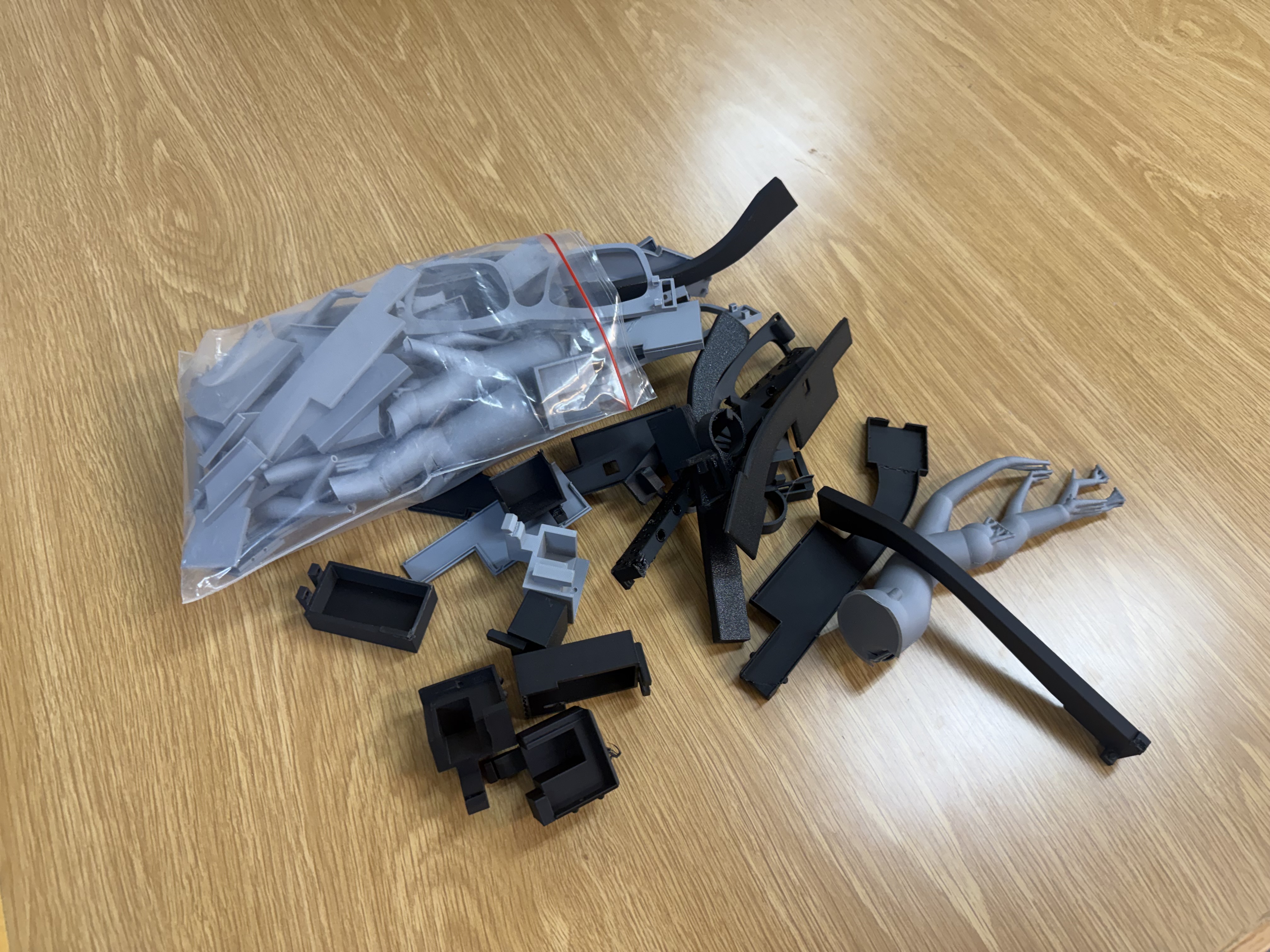
I integrated the first NeuroAR spiral by building the chassis, optics, electronics, milled board, and final packaged glasses prototype.
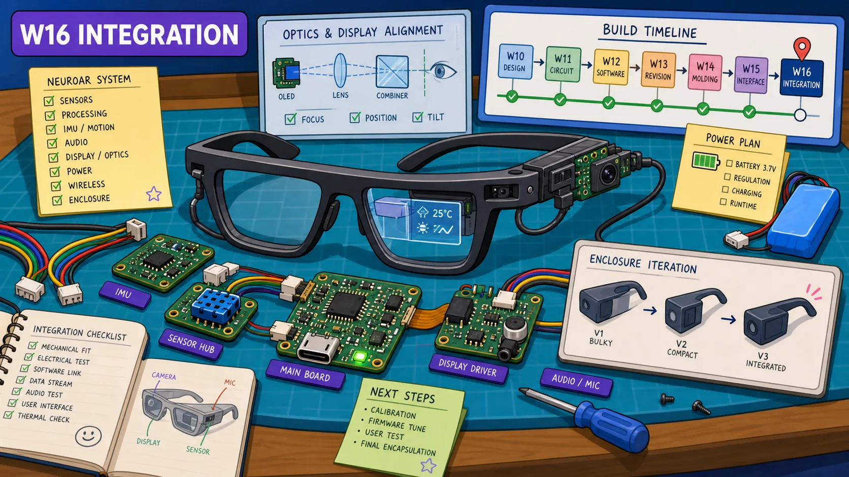
This week was a huge lock-in on my final project. Good news is that I finished the first spiral of the project officially this week (some of it spilled over to get some finalized versions to the following week, but it was mostly done).
It was a lot more trial and error than I expected tbh. This meme shared on Mattermost sums it up.

There isn't much of a group assignment this week, so it will be primarily focused on what I did, and you'll find lots of what I mention here repeated/reflected in my final project development log.
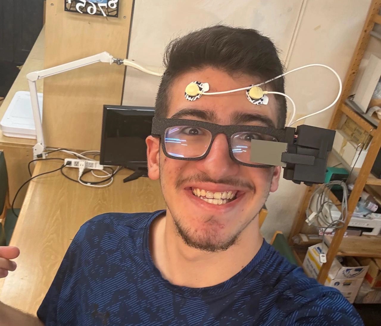
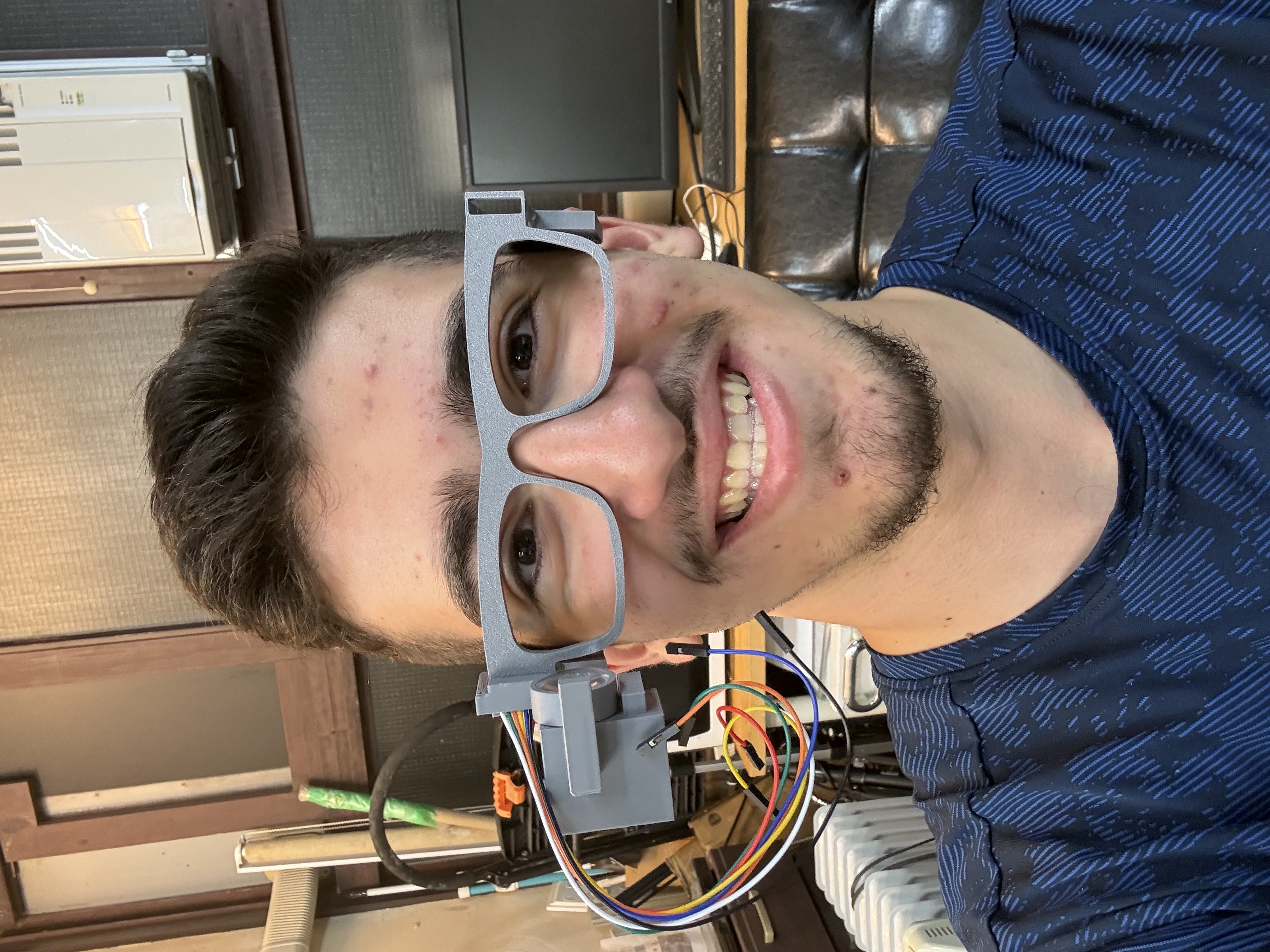
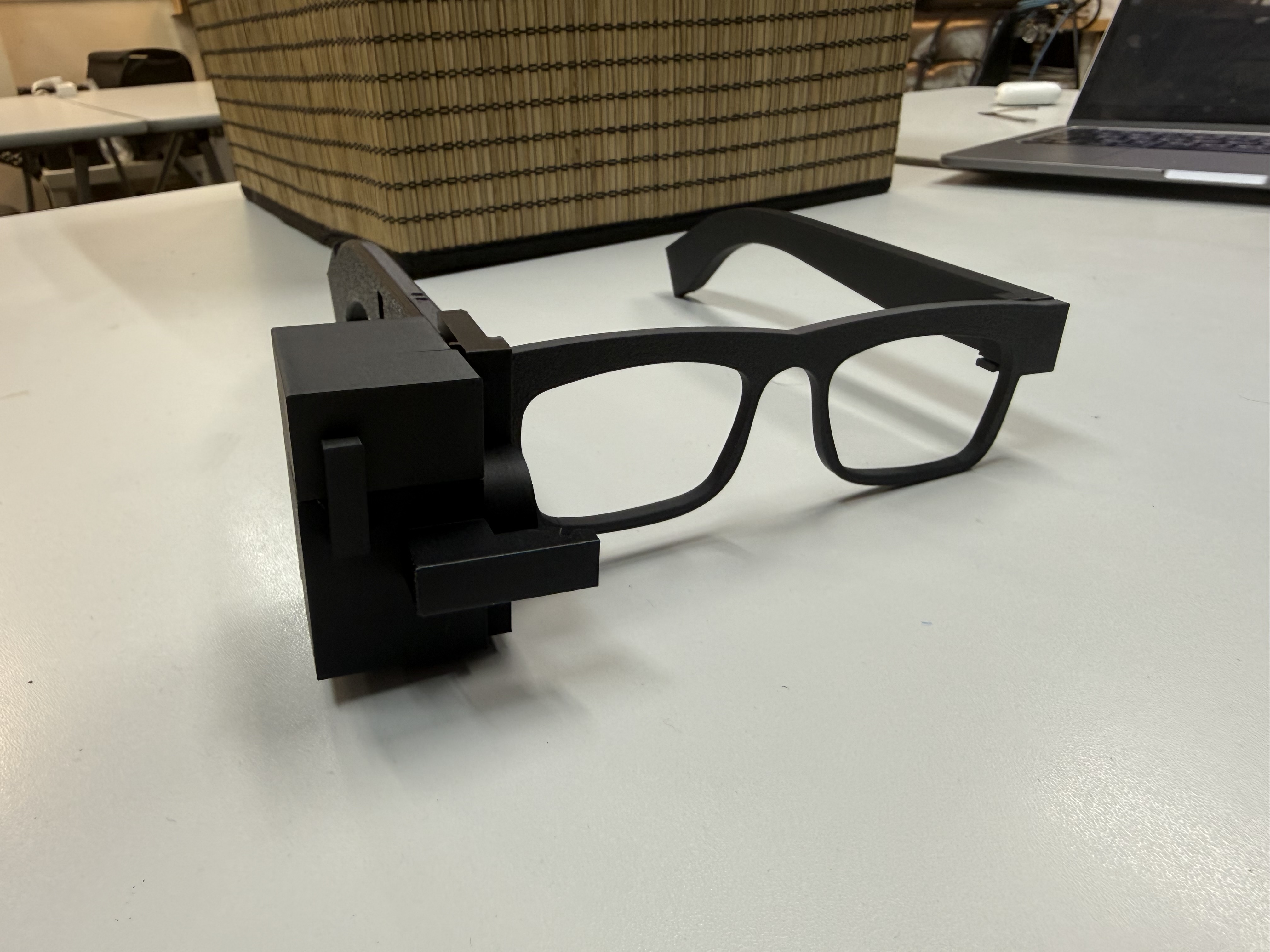
Here's how the glasses look!
Learnings from Global Session
TIME TO GET OUR FINAL PROJECTS DONE....
The assignment is to design and document the system integration of the final project. That means the system diagram, BOM, packaging, mounting, wiring, power, tests, and the final "does this look like a finished thing?" part.
A project can have working electronics, working CAD, and working code, then still fail because the parts were never integrated properly.
Side note from the start of the session, which Neil really emphasized: I need to document how I used AI in my website/project, and I want to write a couple of docs on additional elements relevant to my project like how the newer AR displays are made.
Design stages
Design was framed as conceptual -> preliminary -> detailed design. This matches the spiral idea pretty well.
Conceptual design is the idea. Preliminary design is the architecture. Detailed design is where the screws, cable paths, tolerances, connector choices, mounting, finishing, and test points actually get decided.
A big design point was feedback. The system should make its state visible, so the user knows what happened after an action instead of guessing.
There was also a reminder that basic design principles can get ignored when projects get bigger and more people or money get involved. You need to clearly know and identify constraints to avoid blowing past the fundamentals.
A cool story about Elon and SpaceX. Elon would have no problem paying tens of thousands of dollars to charter a private jet for the employees if they needed to go to a place to get something done, but if a piece they wanted to order while being able to build it themselves he wouldn't approve that purchase.
This built the expertise of SpaceX's team, placed certain constraints on the things that matter (time), and got the parts that became much cheaper to do in-house before the company scaled to where it is today.
DFM and physical design
DFM: Design for Manufacturing.
DFM means designing around the process you are actually using. In Fab Academy, that process might be 3D printing, PCB milling, hand soldering, laser cutting, wiring by hand, and assembling something 12 times because it didn't fit the first 11 times (fun).
The main DFM points:
- use standard components when possible
- design around the machine/process you are using
- minimize the number of separate parts
- use fixtures, flexures, or adhesives when they actually make assembly easier
- use self-aligning features
- make reversible designs when possible
- use fasteners where something needs to come apart again
BOM, packaging, mounting, and finishing
Another big point was that packaging and mounting are part of the actual design.
A board sitting loose in an enclosure is not finished. A wire that can be pulled off a connector is not finished. A part that only works when held at the perfect angle is not finished.
The BOM (bill of materials) matters here too. I need to make a BOM from KiCad and the rest of the project files so the system is not just "some boards and some wires" in my head.
I also gotta have a good finish. A shoutout to the worst integrated final project in Fab Academy.
Murphy's Law, QA, and QC
Murphy's Law is usually quoted as "anything that can go wrong will go wrong," but the useful part is designing around failure modes before they happen.
Neil talked about this a bunch of times before since the first week, but here we go again since it is very important.
It came from missile testing, where Murphy needed to design around the things that could go wrong.
QA is preventing defects. QC is detecting defects.
QC is finding a solder bridge. QA is designing the board, spacing, process, and assembly flow so that the solder bridge is less likely to happen.
A good system integration test is very physical: shake the object, drop it carefully, run it for a long time, turn it on and off many times, check if anything loosens, resets, heats up, or breaks.
Basically, does it survive being a real object? Cuz it is always quite easy to fake a demo., especially nowadays.
Stress, strain, and dynamic failures
Stress is the force on the part. Strain is how the material deforms.
The important part is staying away from the elastic limit. If the part bends past that limit, it can still open and close at first, but each use creeps the material until it fails.
For latches/snap fits, he also pointed at stress concentration. If the flexing area has a sharp inside corner, the crack starts there, so the boring fillet is doing real work.
The easy failure mode to miss is dynamic failure. A part can look fine statically, then fail when it moves, vibrates, gets opened and closed, or hits a resonant frequency.
Neil gave a few mechanical failure examples around this.
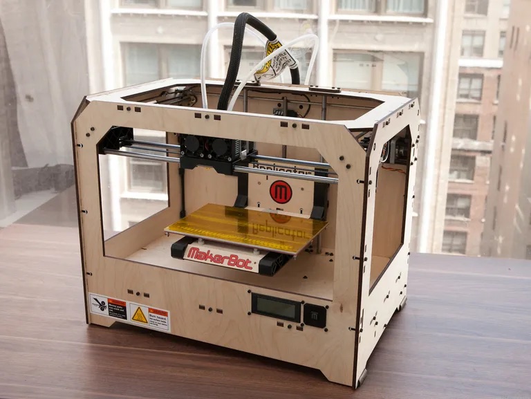
In the MakerBot printer, The nuts were held in place by a thin sheet of plywood, so when the machine was assembled and started printing, the nuts compressed the plywood past its elastic limit.
The plywood flowed outward, the structure loosened, and a printer that worked great at first could start falling apart after a month.
The Moog synthesizer one was also mechanical, even though it sounds like an electronics story at first.
Bob Moog used integrated circuits in sockets so they could be removed and changed, which seemed flexible, but shipping vibration made the ICs work their way out of the sockets.
So the circuit could be right and still fail because the components were not mechanically held well enough, which led to the failure of the company.

The Tacoma Narrows "Galloping Gertie" bridge example Neil gave was about resonance. It was a bridge that was carefully designed for its loads and was already in use, but wind made the guy lines (tensioned cables that stabilize freestanding structures) vibrate like a musical instrument.
That vibration lined up with a mode of the structure and kept pumping energy into it, basically like pushing a swing at the exact wrong frequency.

Wiring and insulation
PCB traces aren't load bearing. Wires can get pulled off connectors easily. Kinda happened with me this week.
The system needs strain relief, so when something gets pulled, the force goes into the housing instead of the wire or PCB pad. In production, power connectors should also be polarized, so there is only one correct way to plug them in.
A few wiring rules to keep in mind: use strain relief on connectors; use polarized connectors for power; avoid insulation rubbing against sharp edges; route wires intentionally, not at the last minute; and leave enough slack to open the system without ripping cables.
A few wiring failure examples were honestly pretty scary because the failure does not always show up the first time you test the thing (people died because of these).
Kapton is a polyimide film/tape used in flex PCBs, laptop display cables, 3D printer beds, motor insulation, and other electrical/thermal insulation jobs.
The failure example was Swissair Flight 111, an MD-11 that crashed in 1998 after an in-flight fire. Kapton-insulated aircraft wiring was one contributor in the larger failure chain.
The failure starts with the insulation getting damaged. Small nicks, rubbing, vibration, and moisture could make cracks in the Kapton around the conductor. Once the conductor was exposed, the wire could arc, and that arc could char the Kapton.
Charred Kapton can become a conductive carbon path, so current can track along the damaged insulation instead of staying inside the copper wire.
That can overload a circuit in a way a normal circuit breaker may not catch cleanly. If a breaker trips and gets reset, the charred insulation can burn along the wire like a fuse.
On Swissair 111, the fire spread above and behind the cockpit, ate through wiring harnesses, filled the cockpit with smoke, cut power to flight systems, and the plane crashed into the Atlantic.

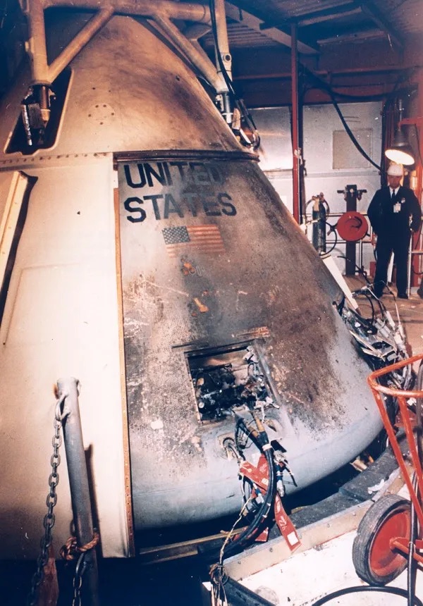
Apollo 1 was a ground test of the command module in 1967. The crew was inside, the cabin was pressurized with pure oxygen, and a fire started before launch ever happened.
The worn wiring was one of the causes. The capsule kept getting opened and closed during tests, so wires rubbed a bit more each time, the insulation wore down, and an arc could start the fire.
Then the other system integration failures stacked up: flammable material inside the cabin, high-pressure oxygen, and a hatch that could not be opened fast enough. That is what made the failure deadly.
The Airbus A380 wiring problem was a configuration-management failure hiding inside a wiring problem.
The A380 had around 530 km of wiring. Different Airbus sites were building parts of that system with different CAD setups in Germany and Spain.
So the digital model split into multiple versions of the truth. When the fuselage sections and wiring harnesses came together in Toulouse, some wiring designed in Hamburg did not match the aircraft. Some runs were too short to connect the sections properly.
That meant pulling out and redesigning wiring that had already been routed through a giant plane. The delay pushed the A380 roughly 2 years late and cost billions.

Components, power, and brownouts
Components also fail when they are pushed past their limits.
Transistors can blow when current or voltage goes above what they can handle, and the damage can be cumulative through electromigration. Voltage regulators can blow if power is connected in reverse. Diodes can help block transients.
Power supply compliance is also important when dealing with well... power supplies. As a load asks for more current, the supply voltage can droop. A motor or big load can work alone, then cause the processor to reset once everything is connected together.
That is the brownout problem. The code can be fine, PWM can be fine, and then the processor resets because the rail drops under load. That must be so annoying to debug because it looks like a software problem at first.
Bypass capacitors are the fix. Small capacitors help with high-frequency noise, and bigger capacitors provide local charge when the supply cannot react fast enough.
This is why checking the power rails matters. If the rail is doing something crazy, the code is probably innocent.
Grounding and EMC
Electromagnetic compatibility is basically about grounding, and grounding is way more subtle than I expected.
A motor shares a ground path with a processor. The motor asks for current, that current returns through the ground wire, the wire has resistance, and suddenly the ground voltage is jumping up and down.
So the supply might look fine, but the ground reference itself is moving. That is a ground loop type of problem.
The fix was described as a ground mecca, or one place where ground is defined. The trick is the wiring: return currents need paths that stay out of each other's way.

Software failures
Software has its own system integration failures too.
Memory leaks happen when memory is never returned, and eventually the program runs out. Buffer overflows let a program access memory outside what it should touch. Race conditions happen when threads finish in different orders. Variable scope can also create weird bugs when the wrong part of the program controls state.
The Rust / Go / C / Python comparison was interesting. The rough lesson I took is that some languages make certain mistakes much harder, while C makes you responsible for a lot of scary details. For security-critical code, casual C is probably asking for pain, lol...
Dependencies are another problem. A lot of open-source libraries are maintained by small teams, so you can inherit issues from code you did not write and do not fully understand (I talked about this before in Week 15.
Algorithms can also fail by scaling badly. Something can work with 10 samples and break with 10,000. This is why understanding growth and scaling matters.
Units, supply chains, and failing early
The Mars Climate Orbiter crashed because one team used English units while another used metric units. This small mix-up caused the spacecraft to miscalculate its altitude and destroy itself in the Martian atmosphere.
Some of examples sound obvious, you need to have clear units, assumptions, and ownership. Even some of the best scientists in the world could face these simple mistakes, so they should account for them.
Supply chains are another system integration issue. A part can exist today, then disappear or become hard to get later, and suddenly the design has to change.
Failing early is better than failing late. The Starliner vs SpaceX comparison was a good reminder of that: fast feedback loops matter. SpaceX just launched a lot more and learned much faster from that becoming the behemoth it has become today.

Lifecycle and design
System integration also includes lifecycle.
Can the system be opened? Can it be repaired? Can parts be replaced? Can anything be reused at the end? Right-to-repair sounds like a policy topic, but in a student project it starts with screws, labels, and access.
There was also a simple design reminder I liked: make beautiful things that are nice to look at.
Building NeuroAR
I dedicated this week to officially finish my final project (the first spiral). As you will see reflected on my final project page, this first spiral's goal is to have a working AR display and an EEG system in one finalized package.
That's what I worked on. I learnt a lot from this process. To be honest, I thought this step would be much easier but turns out it takes a lot more trial and error than I expected. Some of the work of this extended to the following week, but I got it done.
So far, I have learnt and built the independent systems that are related to my glasses, like the EEG board I built recently to test my DIY EEG system, I documented that earlier in Week 15.
Now, it was time to start designing actual glasses :D Here were the requirements I set for this spiral:
- Needs to use lenses from my current glasses, creating your own custom lenses is expensive and a whole new process.
- The glasses design shouldn't look too ugly, and it should have an appropriate space for electronics, a simple button input, the display (and its optics), and the EEG system.
- I should design for balance of the glasses between the front/back and the left/right sides, and enabling the glasses (when display is detached) to have a proper hinge.
- The design should adequately handle and hide cables, the criteria is that people shouldn't be seeing wires from the outside.
- The design didn't need any screws, everything snaps into place. This wasn't really necessary, but I wanted to learn how to make satisfying clicks like that, and I ended up liking this concept a tbh.
- Of course, it should integrate all the final project requirements and survive the tests Neil mentioned.
It is important to note that while I will be describing the general process that worked, a lot of things didn't really work from the first try, and needed to go through lots of trial and error to get it right.
I will try my best to note the main setbacks and design changes I made as I walk you through my design process.
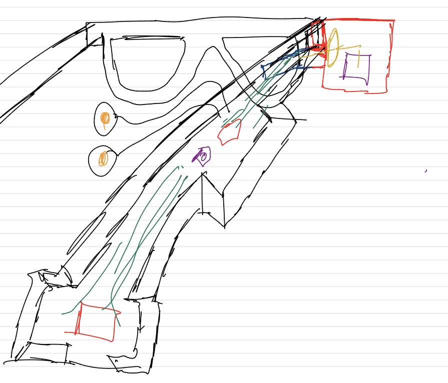
This is the design that I had sketched for this spiral. I know my drawing is pretty bad, but the idea is that the display sits on the side at a specific distance so I can actually see it after the light passes through the optics. I also wanted the electronics split across connected boards, the EEG signal-processing chip close to the temple electrodes, the main XIAO chip at the back to balance the glasses, and enough weight on the left temple to balance the left/right sides.
The idea was also to make it possible for the display compartment to be removable.
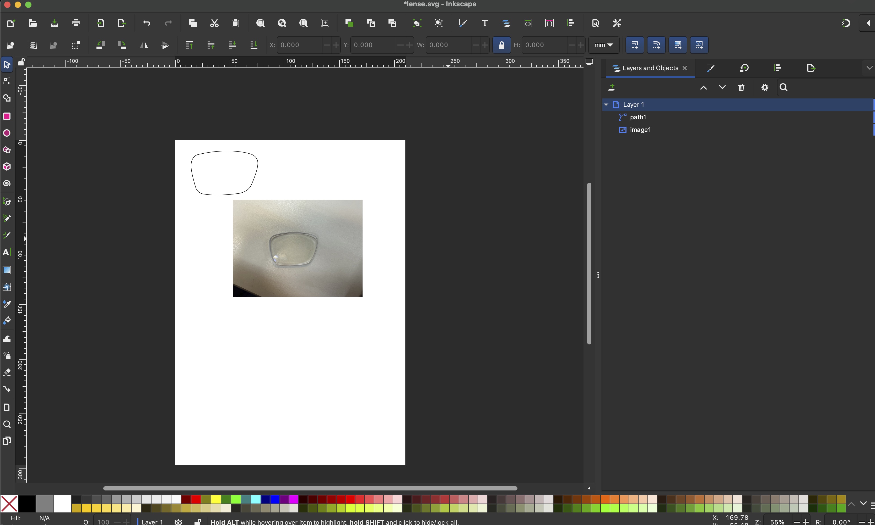
Creating the Chassis
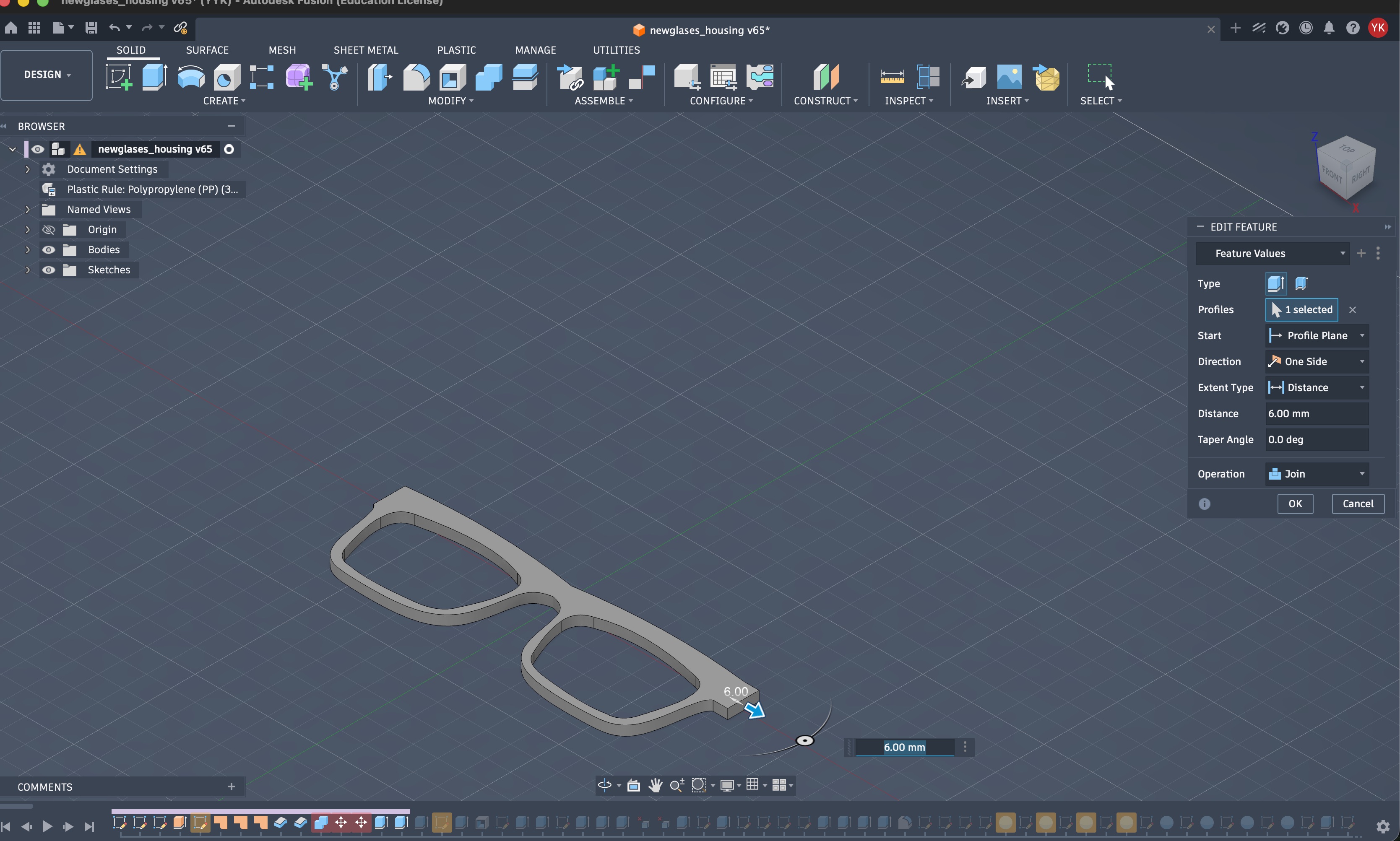
For designing the chassis, I decided to start from the lenses up. I started by taking a picture of my lenses and creating an SVG/DXF of their shape to import it to Fusion.
I imported it to Fusion and designed the frame. I made it look similar to any normal glasses. I am not a big fan of crazy weird glasses design.
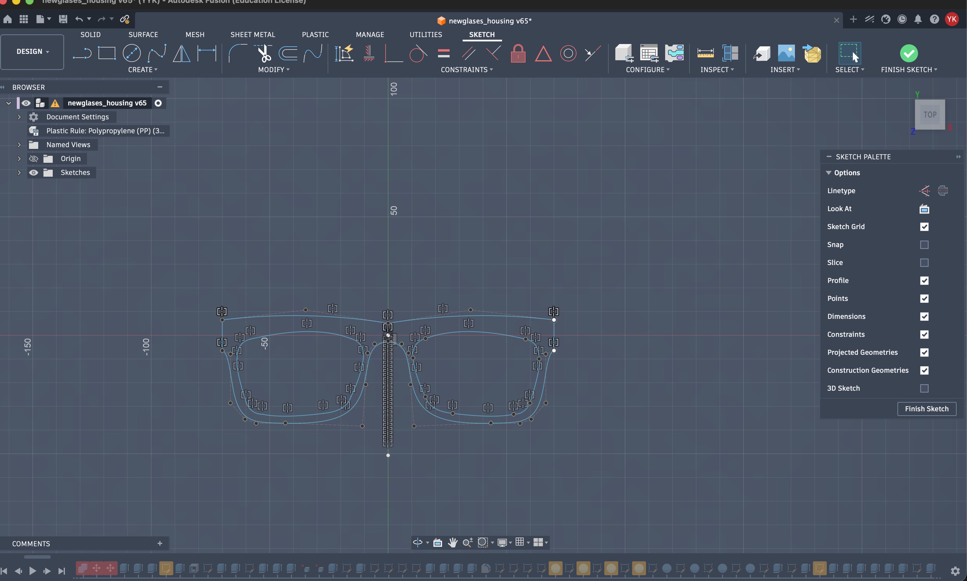
I extruded the design and made the main frames. I made it look better that what I designed previously and it went through an iteration where the top was too thick.
I also extended the sides so there is more space to connect it with the somewhat thick temples.
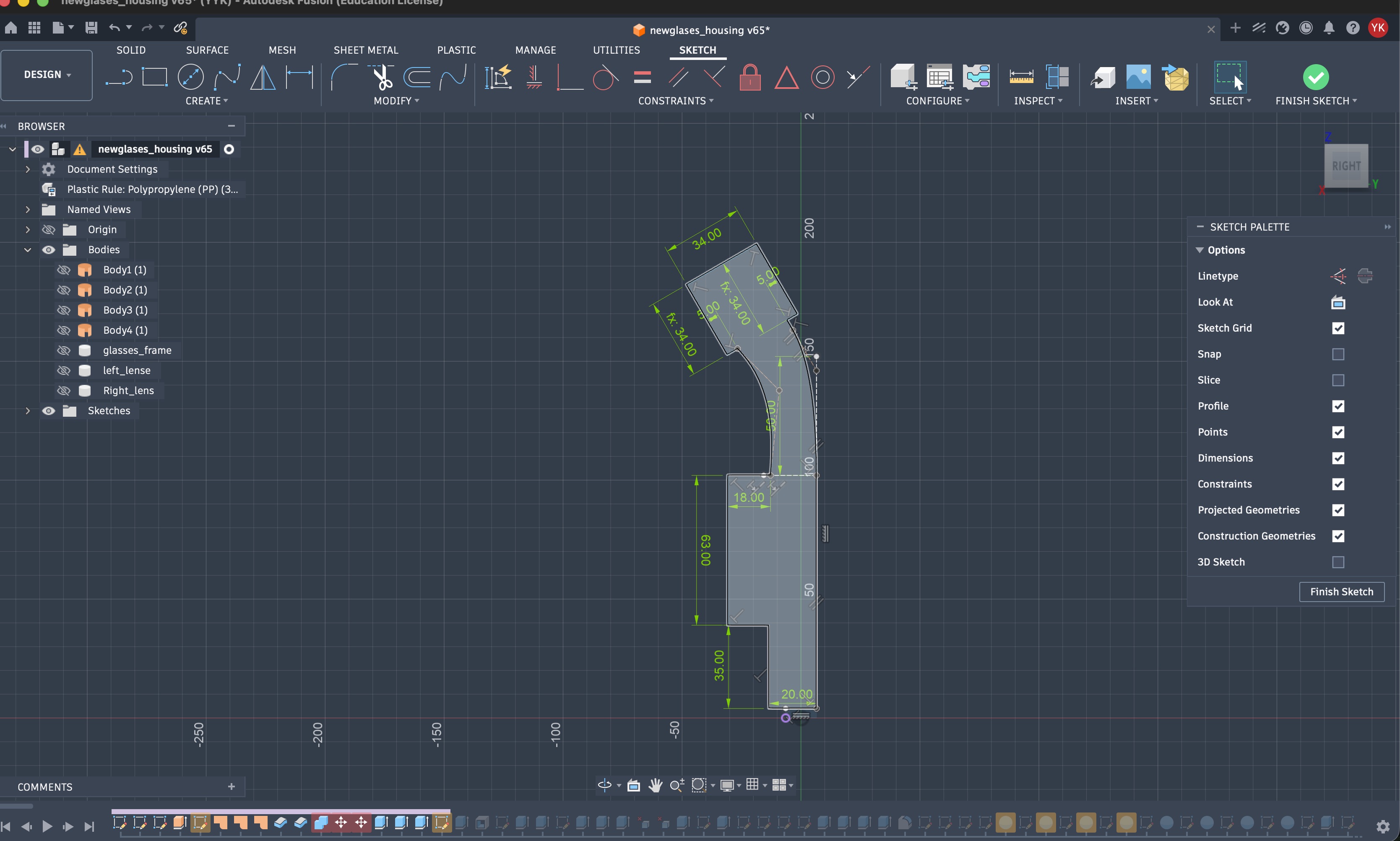
Then, I created the design of the main temple on the right, making sure there is enough space to place all the components on the board that'd fit there, and that it is deep enough to be a solid enclosure for everything.
At the end, the whole depth of the right temple including the cover (the one that encloses the electronics) is about 6 mm.
I used some parameters to define the size and shape of the temple.
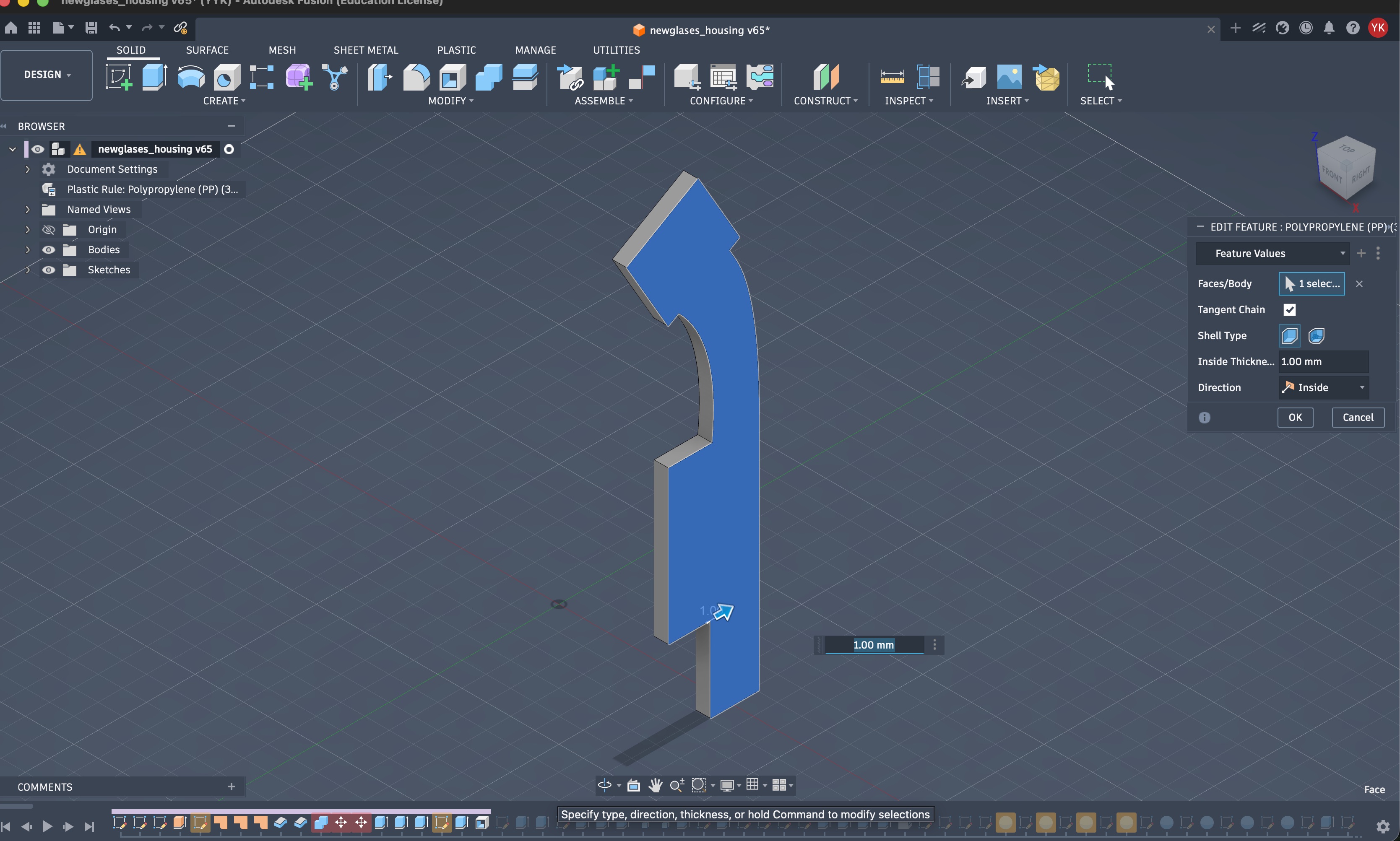
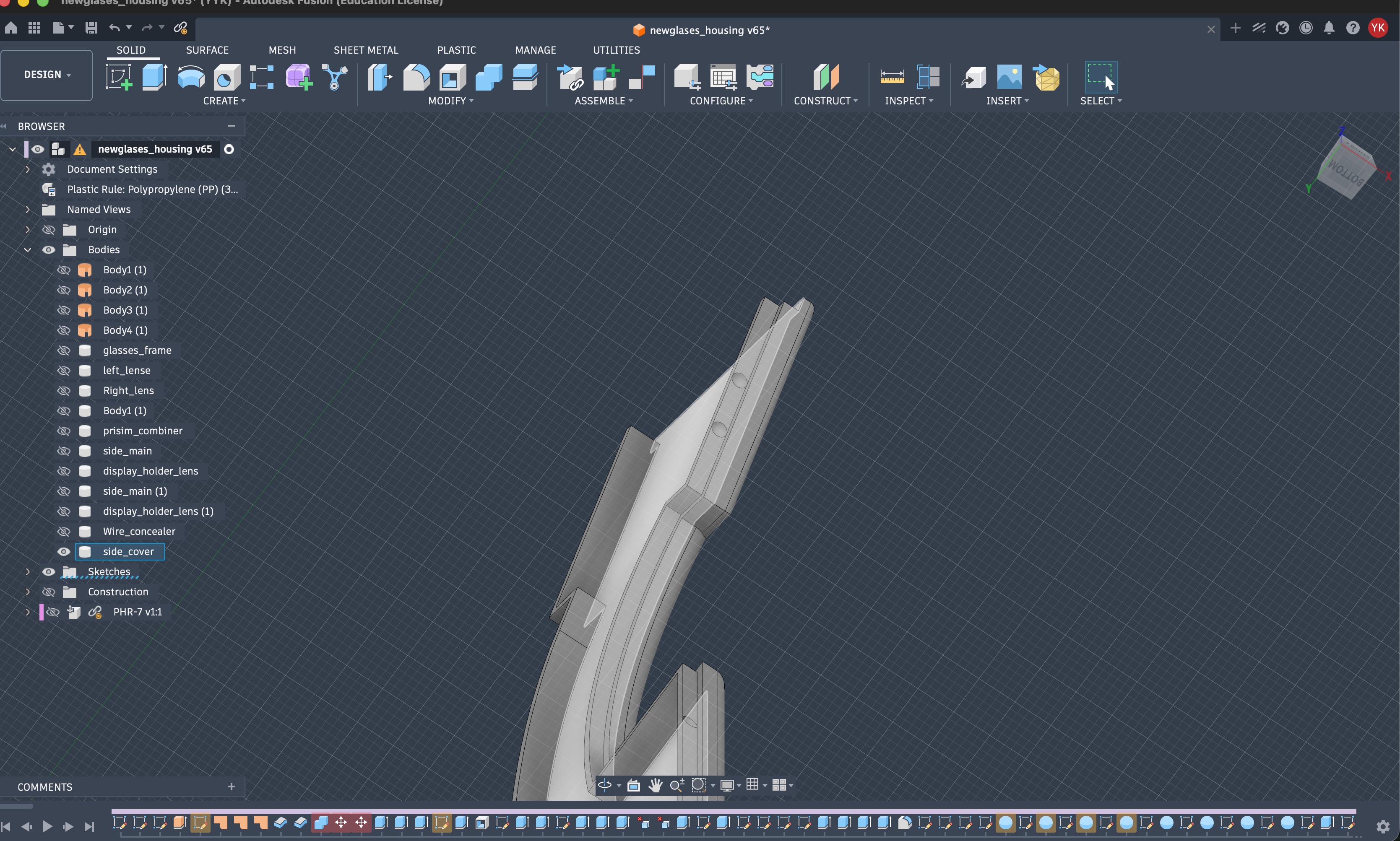
I wanted things to snap easily together without screws, so I found this video that taught me how to create a sturdy snap fit.
The spheres on the temple made body was 2 mm, and I had that same cut into the inner edges of the cover.
One important thing that changed here was the thickness of the main body. Over repeated use, they were prone to break. I fixed that by making the 3d print infill a bit higher (I'll talk more about this down below) and I made them a bit thicker.
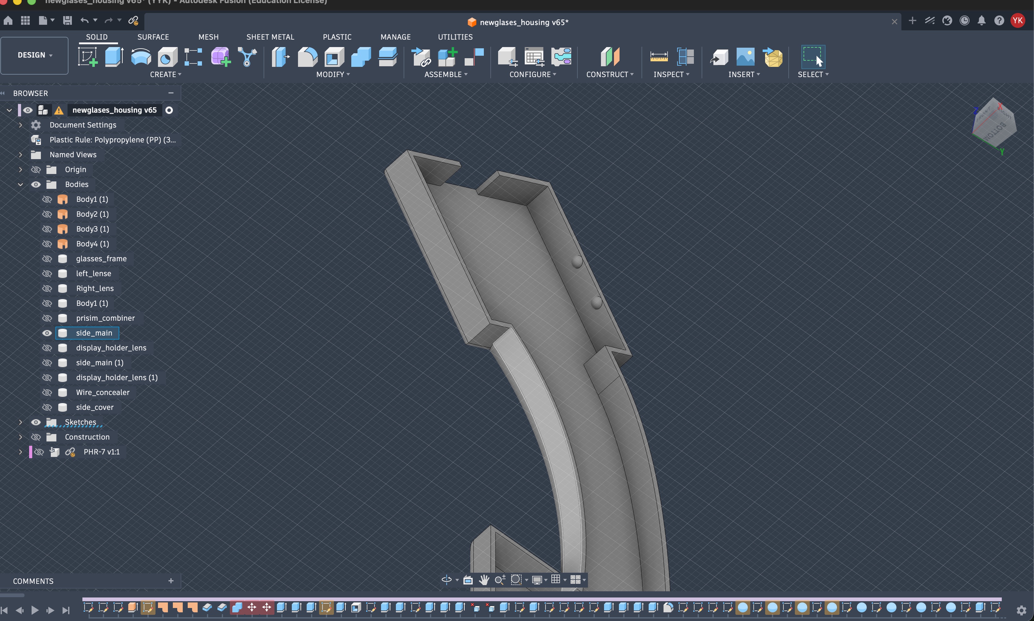
Next, was making a slot for the connector to the display module. It went through a couple of iterations till I got the size, clearance, and chamfers right. I imported the model of the JS connector I was planning to use.
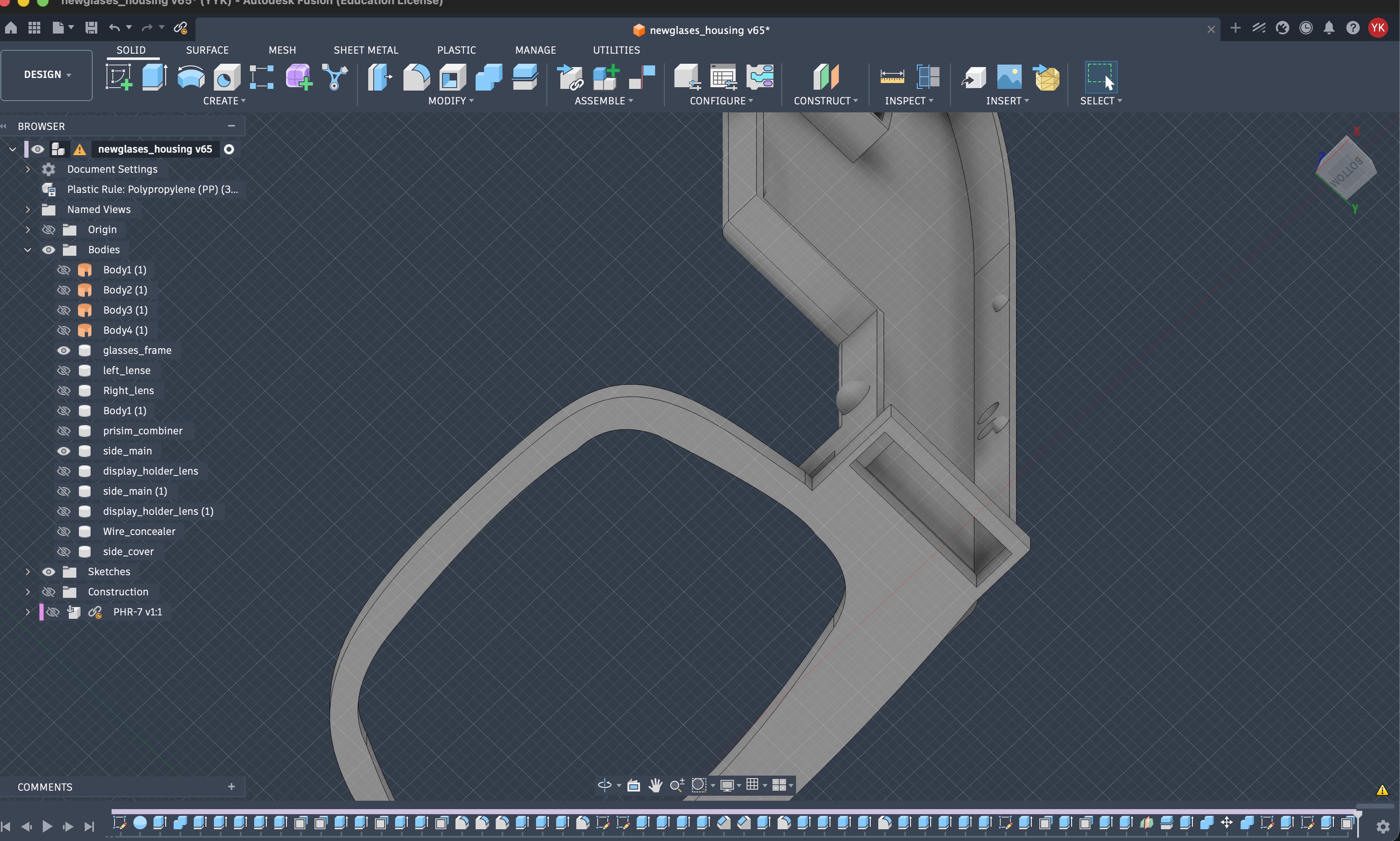
Then, I started designing the hinge. I thought initially for this model I would just print the parts together and have the hinge "built in." It was a terrible idea, and as soon as I tried to move the side the hinge broke.
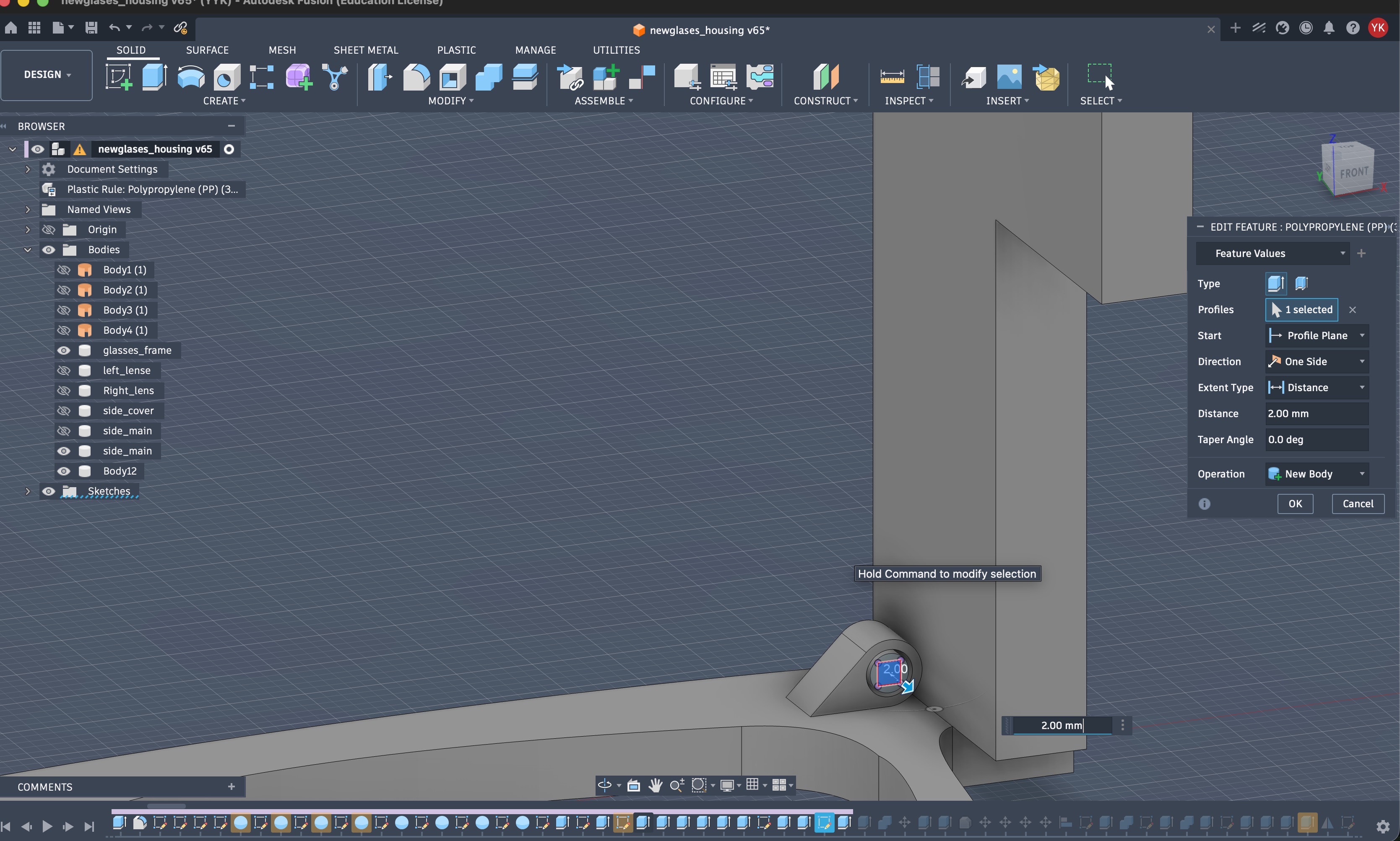
After a couple of attempts (that involved printing them a couple of times), I found this tutorial. I took inspiration from it to design this hinge.
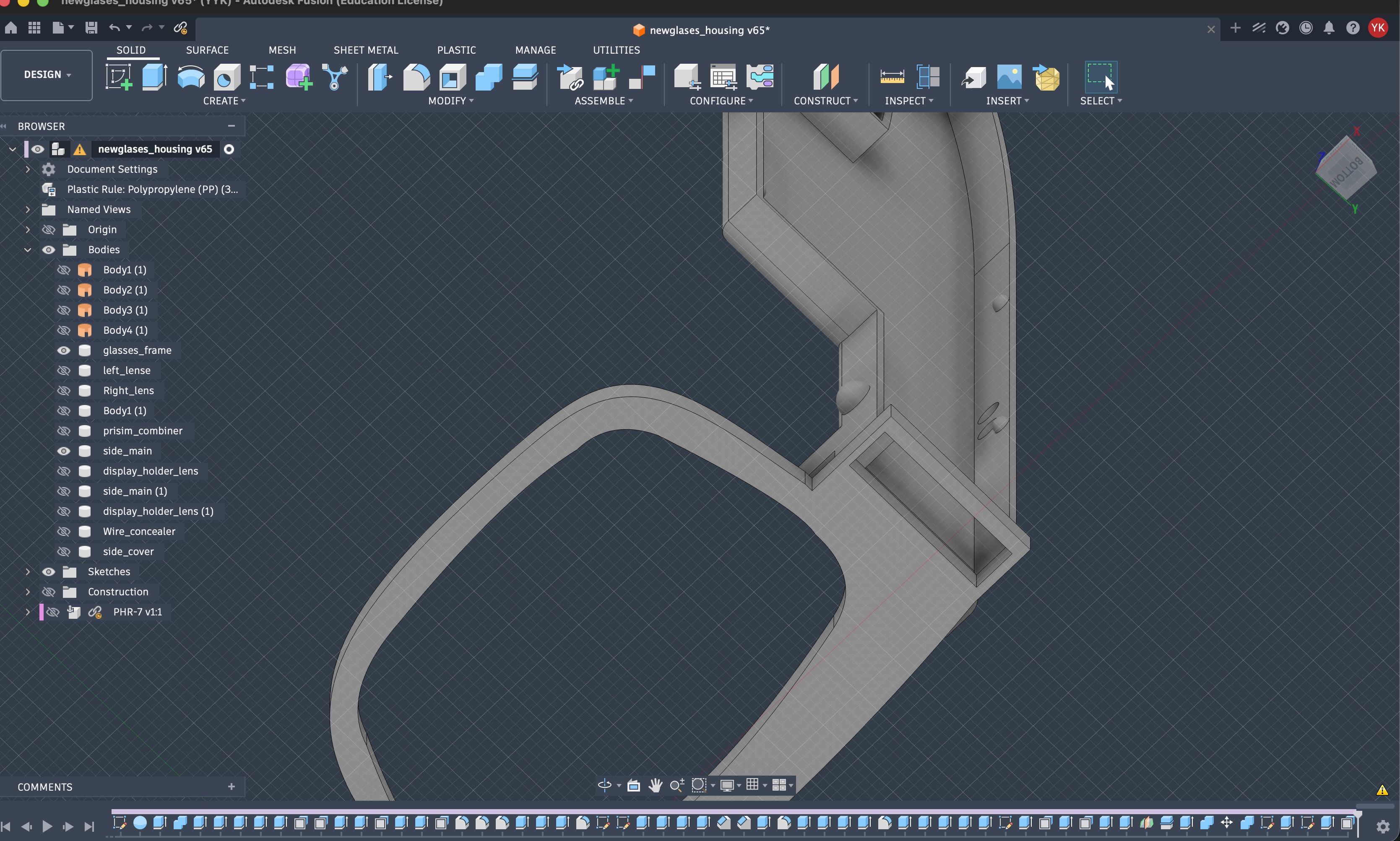
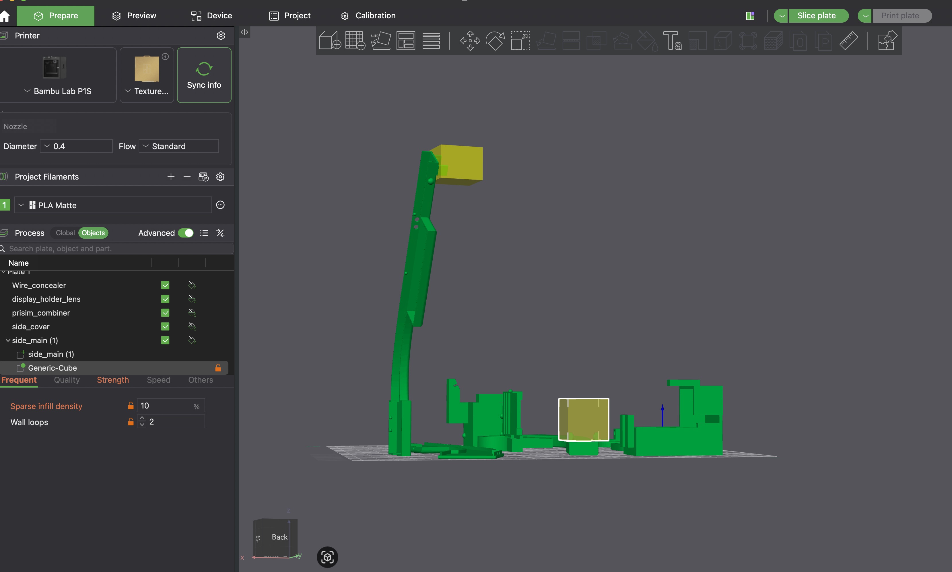
15% infill density with 2 wall loops worked well for me. I was printing with Matte Black Bambu PLA (more on the printing process/results later).
A note here too is that in my later versions, I fillet the temples to make it more wearable.
Creating the Optics
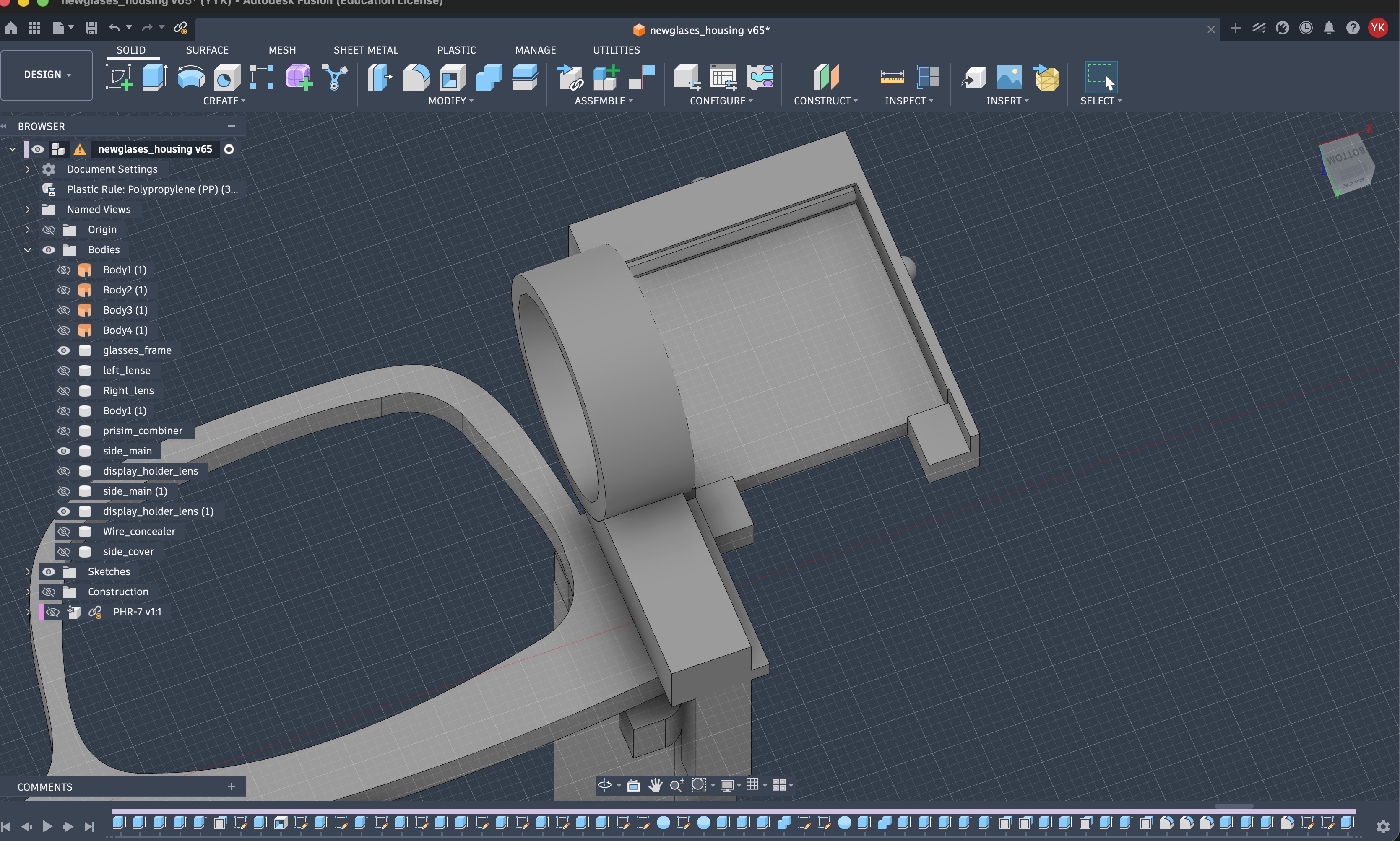
For the optics and the display module, I started by designing the display module, and adding a slot for the convex lens whose purpose is to reduce the distance needed to be able to view what's on the screen properly. On the final project page, I will have the specific components I ordered and links to them.
I also want to write a separate page explaining how optics in some commercial AR glasses work and how they compare with this approach.
The convex lens has a 22 mm diameter, and this display holder also snaps to the temple of the glasses.
To recall, here are some of the calculations I did previously without the lens, and with the lens I was able to reduce the distance by about half. This video was an initial inspiration for me in designing this display module.

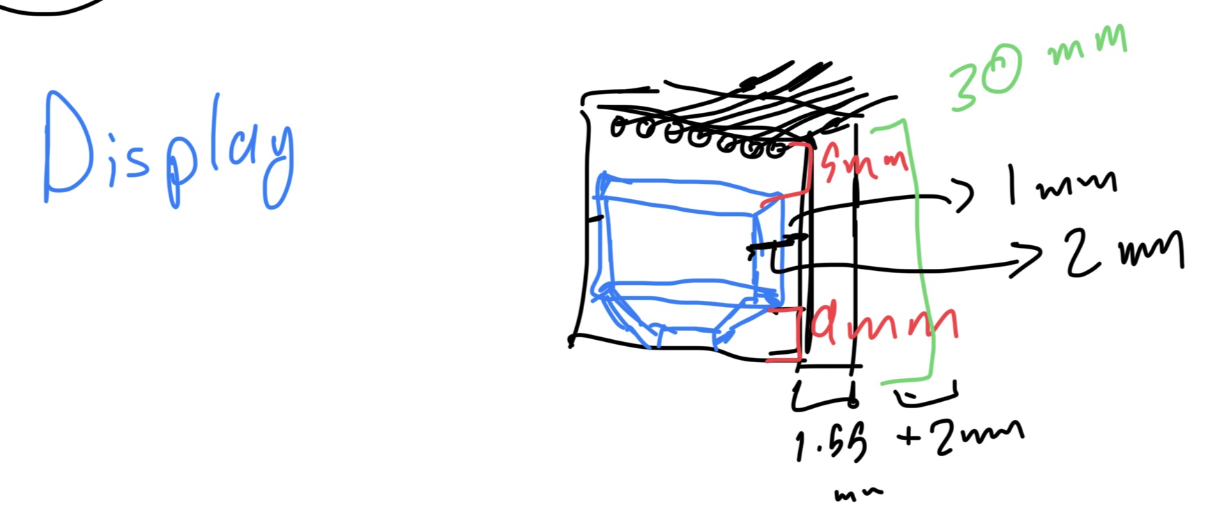
Here's an initial image of some of the sketches and measurements I was taking. Since I was going for the slot holding the display in its place without any screws, I needed to consider the small manufacturing differences between each of the colored displays I ordered (cuz during testing I broke one of them by letting it fall).
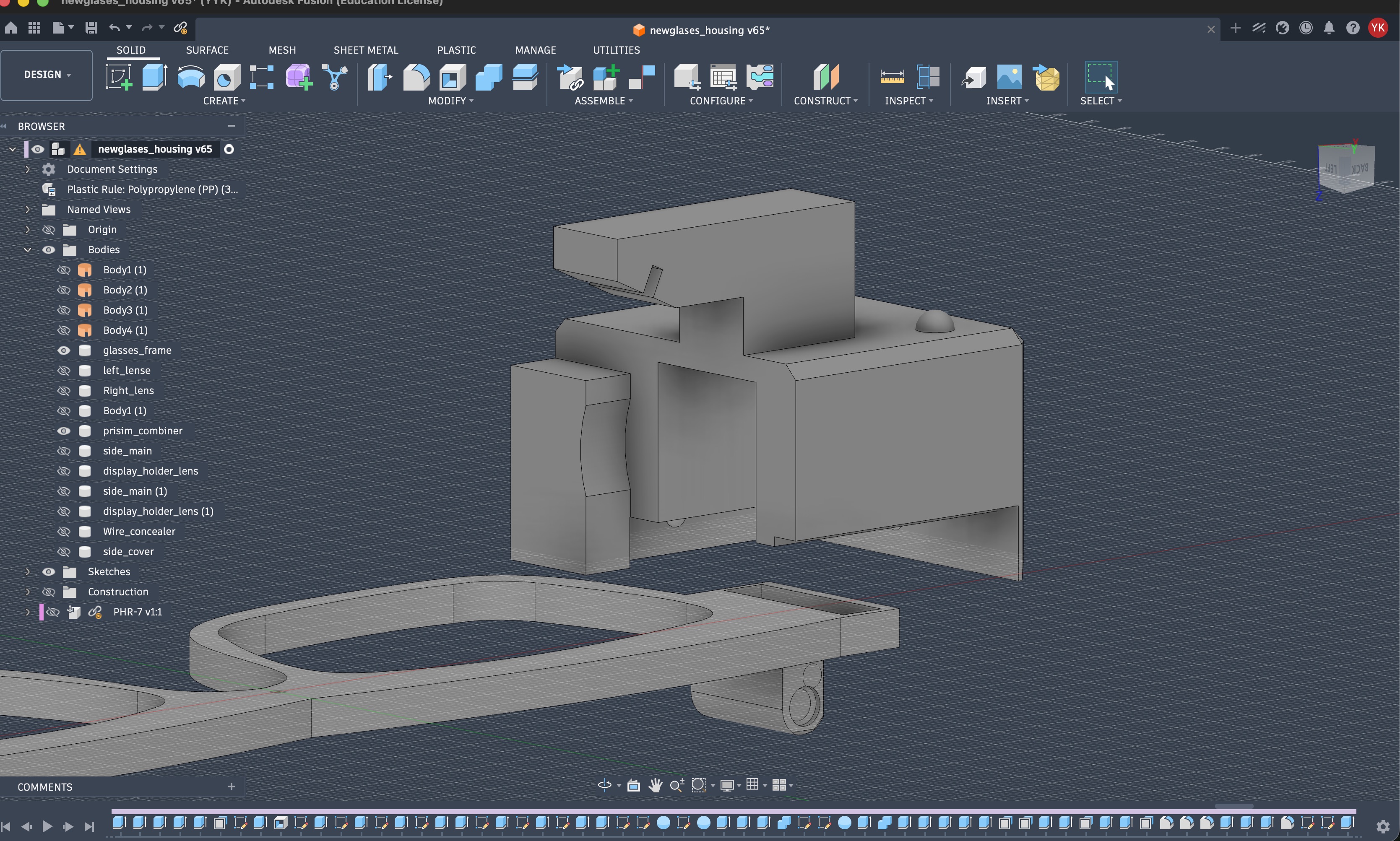
Now, I needed to put the prism on top of the display so it refracts the light properly, where it passes through the lens into a combiner (mirror) to my eye.
This has multiple uses. When printed in black, it won't allow any additional light to get in which makes the image I see sharper, it holds the combiner mirror held at an angle, and it would obviously hold the prism in place. It also snaps onto the display module.
The chamfers you see here were only added later on after a few iterations to make this fit seamlessly with the cable concealer (more on this below)
As for the combiner, that is a 45202 mm piece of mirror acrylic that fits in that slot. It was laser cut.
After I built it and tested it out, I wanted to make sure I could route the cables while maintaining the no-screws rule I made up, lol.
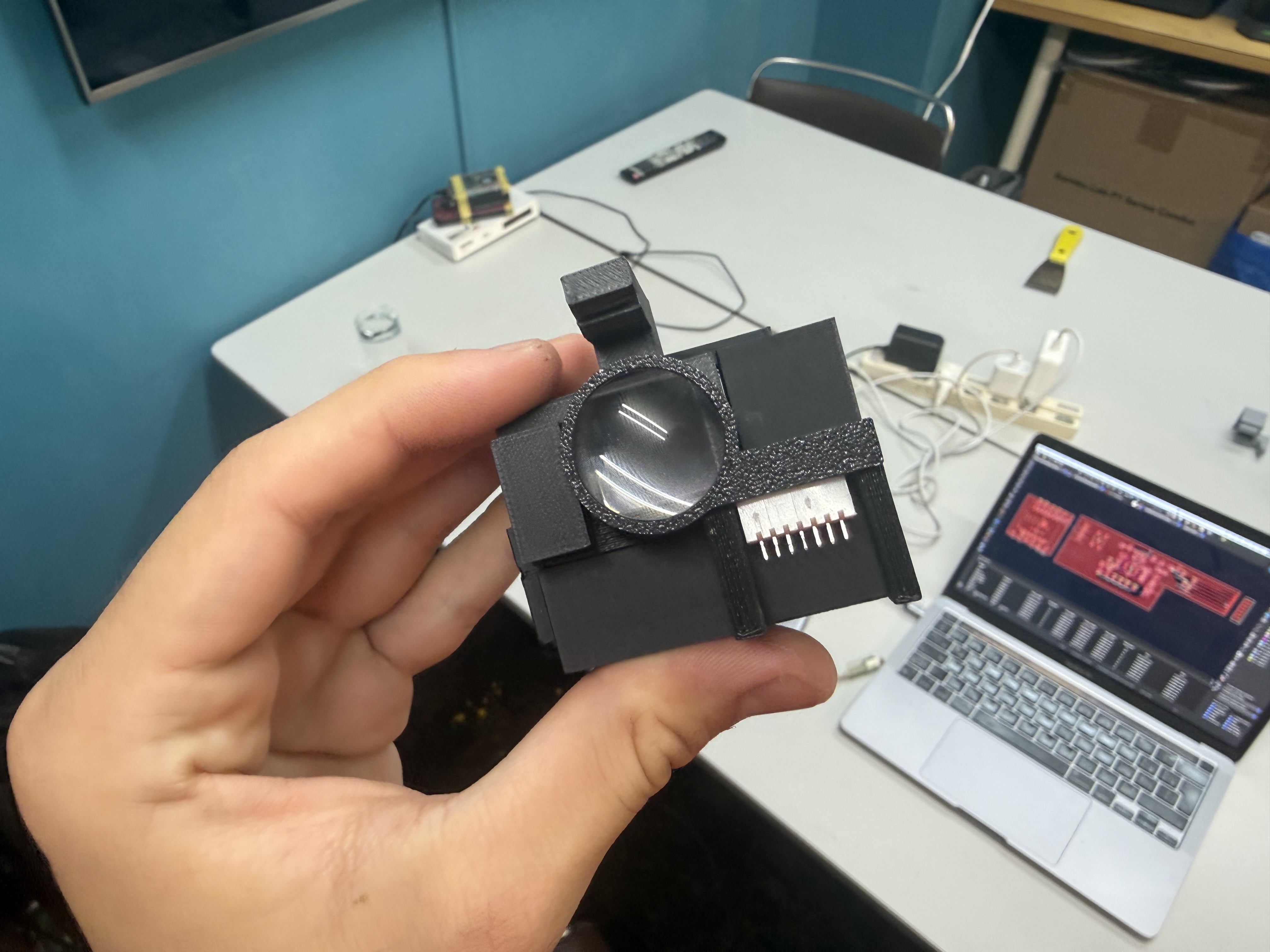
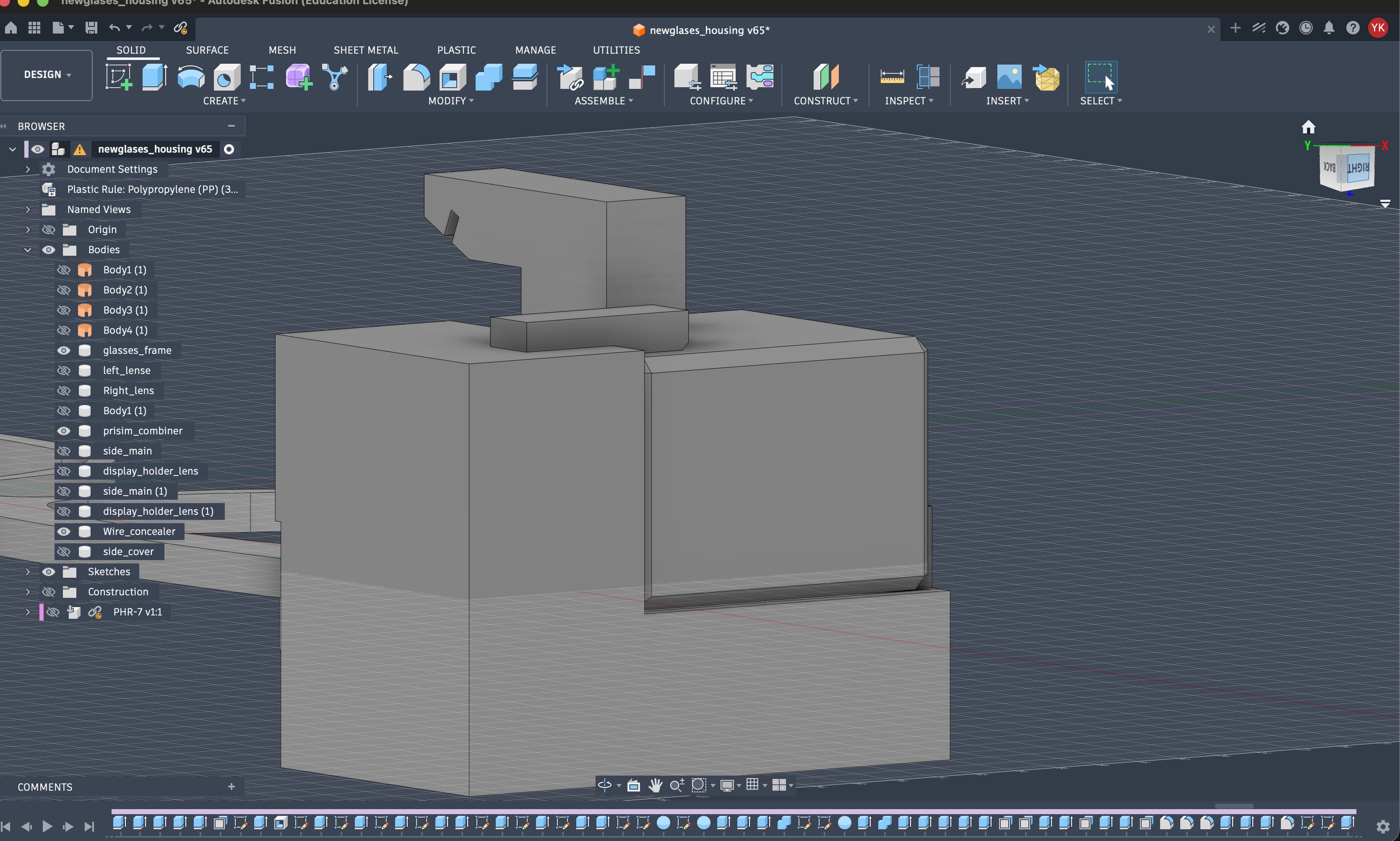
Then, I designed the wire concealers that snap onto the prism holder.
After a bunch of issues I faced with some dimensions or having different parts being too weak, I was able to fit everything together nicely. The design was edited slightly after doing the electronics, but generally this is how it looked like, and I used my own lenses for the glasses.
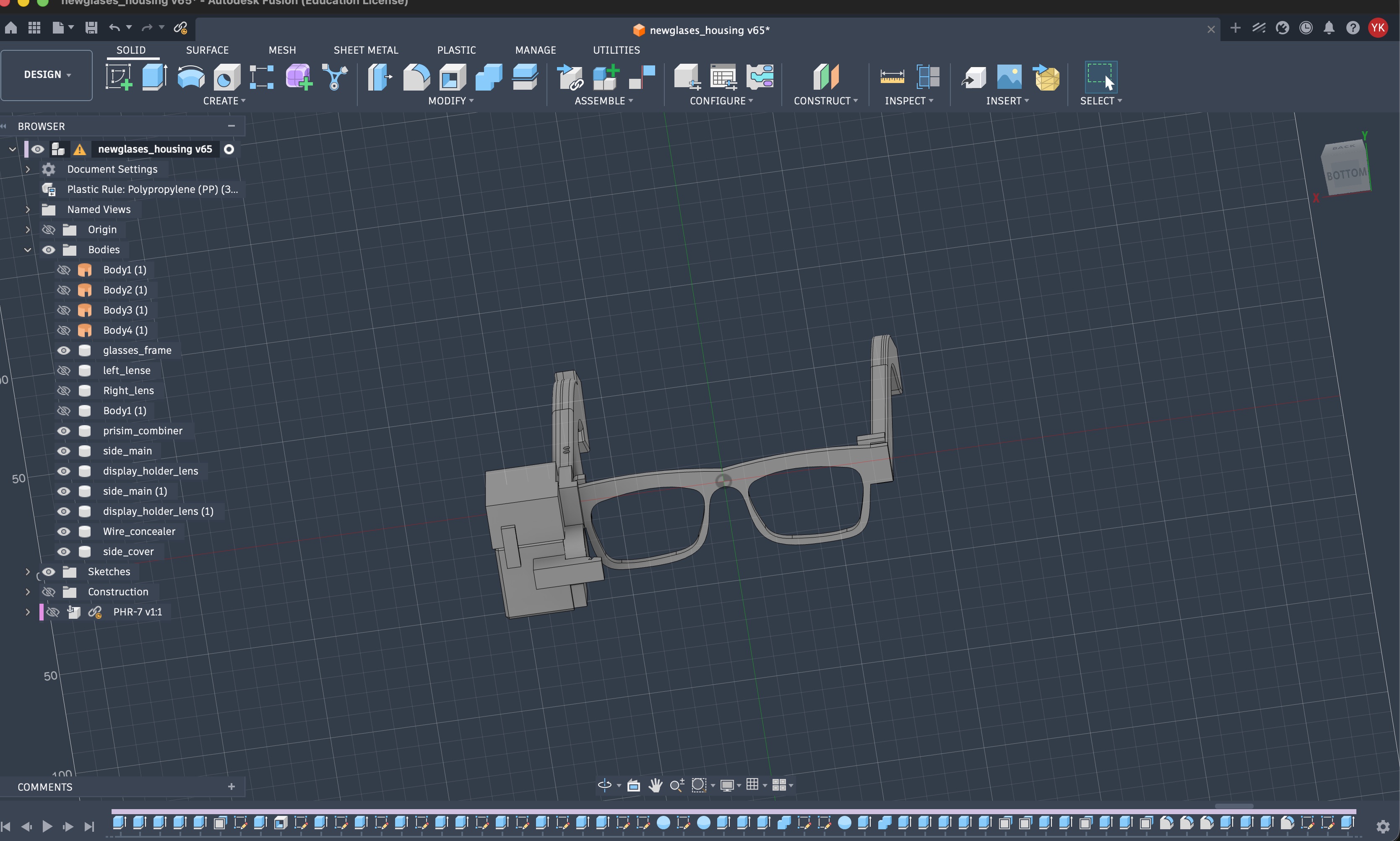
One note, I have this connected and running on an external power-bank with a USB-C cable connecting to the XIAO from the opening at the back of the right temple. This also helps with balancing the back and front of the glasses by slightly applying pressure to the bottom, helping the stability of the glasses. :D
Building the Electronics
This part came from the smaller electronics experiments I had already done in previous weeks, especially the display boards and the DIY EEG board.
The first EEG-ish version was the learning board I explain in the dev log. It used op-amps, a VMID bias point, a SAMD11 to read the analog signal, and the XIAO ESP32-S3 to process it and show rough bars on the OLED.
That board was useful because it made one thing very clear: body signals are annoying to work with. The signal is tiny, the body picks up noise from the room, and without a stable reference point the readings can just float around or saturate.
For the glasses version, I needed something more integrated. The earlier op-amp + SAMD11 setup had too many parts for the temple of the glasses (and was unreliable), and every extra part meant more routing, more soldering, more debugging, and more surface area for noise to get into the circuit.
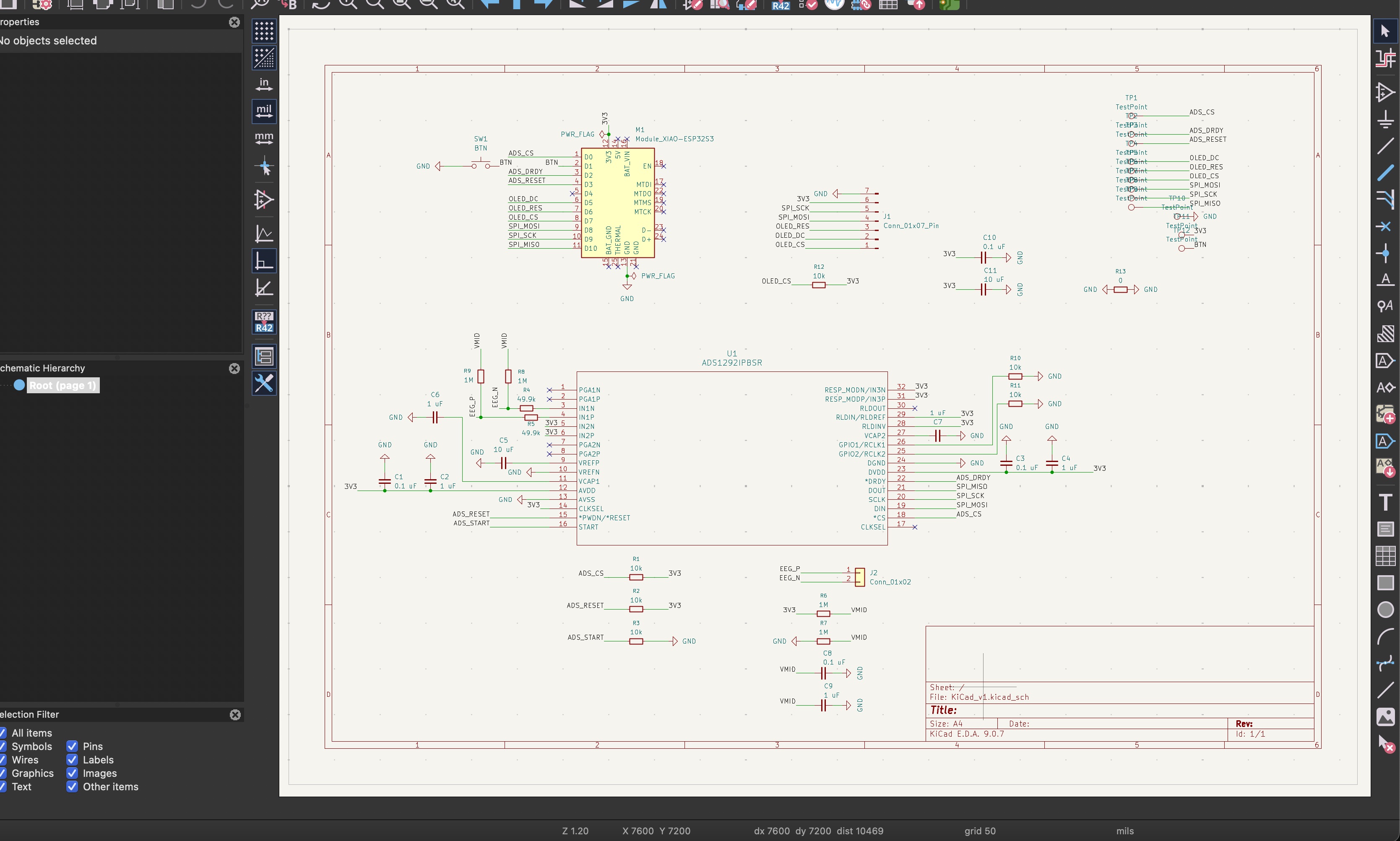
So I moved the schematic to the ADS1292. It is a biopotential front-end, so it already includes the sensitive parts I need for this spiral: differential input, gain, a high-resolution ADC, reference circuitry, and SPI communication.
This does not make the project magically become perfect EEG. It just gives me a better first platform. For this spiral, I am mainly trying to detect strong forehead signals first: blinks, eye movement, and other large biopotential changes.
Clean EEG with only two electrodes is still ambitious. The goal here is to make the following work reliably: body signal -> glasses electronics -> XIAO processing -> display feedback (+ other types of interfaces).
The electrode setup is two forehead electrodes. A third reference / RLD electrode would be better electrically, but for this spiral I cared a lot about the form factor too. The obvious place for placement of the electrodes was the forehead is practical because there is no hair in the way and blinks / eye movement are easier to pick up there.
Right after the electrode connector, I added the 49.9k resistors before the ADS1292 inputs. These are not there to amplify the signal. They are there as protection/current limiting between the body and the chip.
That matters more for EEG than a normal sensor board because the input is literally connected to me. The ADS1292 input impedance is high, so these resistors make the input less fragile.
I also added 1M resistors from EEG_P and EEG_N to VMID. This is one of the parts that makes the circuit make sense. Without a path to a known voltage, the electrode inputs can float around, and then the ADS1292 can saturate or read nonsense.
The 1M value is intentionally large. It gently biases the input to the middle without strongly pulling the body signal down. So the board gets a stable center point, but the small EEG changes can still appear on top of it.
VMID itself is made using two 1M resistors between 3.3V and GND. That creates a middle voltage around half the supply.
Since the board only has one 3.3V supply, the signal needs that middle point. Otherwise the ADS1292 would only have room to measure in one direction, which is not what I want for a signal that moves up and down.
I added the 0.1 uF and 1 uF capacitors on VMID to smooth it. If VMID is noisy, then the "center" of the EEG signal is noisy too, and that gets mixed into the measurement.
The small 0.1 uF capacitors are bypass capacitors, so they deal with fast power noise close to the chip.
The larger 1 uF and 10 uF capacitors are there for slower changes and local power stability. Basically, when the chip or display suddenly needs current, the nearby capacitor helps instead of letting the whole rail dip.
For EEG, this is important because the useful signal is tiny. If the power or reference wiggles, the ADS1292 can measure that wiggle as if it came from the electrodes.
The ADS1292 also has reference / VCAP pins, so I added the capacitors those parts need to stay stable.
I reached there by looking at previous works in the space and with the help of multiple AI tools to cross verify and validate the approach.
I also used 10k resistors on some control lines so they do not float when the XIAO is booting. For example, chip select lines should have a default state, and reset / start should not randomly change just because the microcontroller pin has not initialized yet.
For the color OLED, I kept it on the same SPI bus as the ADS1292, but with its own chip select. Sharing the bus is fine, but both devices should not be active at the same time.
So this schematic is not the final perfect EEG headset, but should do the job for this spiral. The connections to the XIAO are quite straightforward.
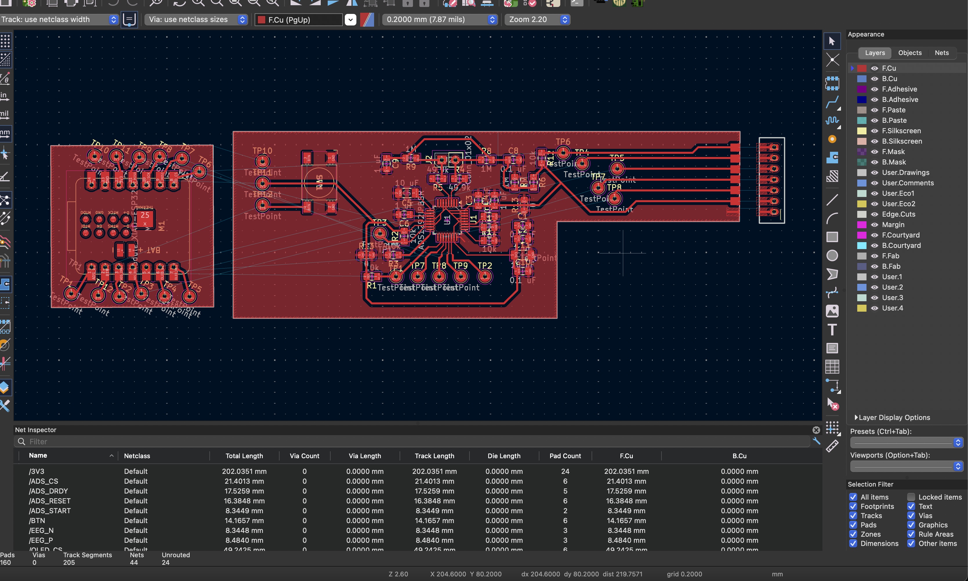
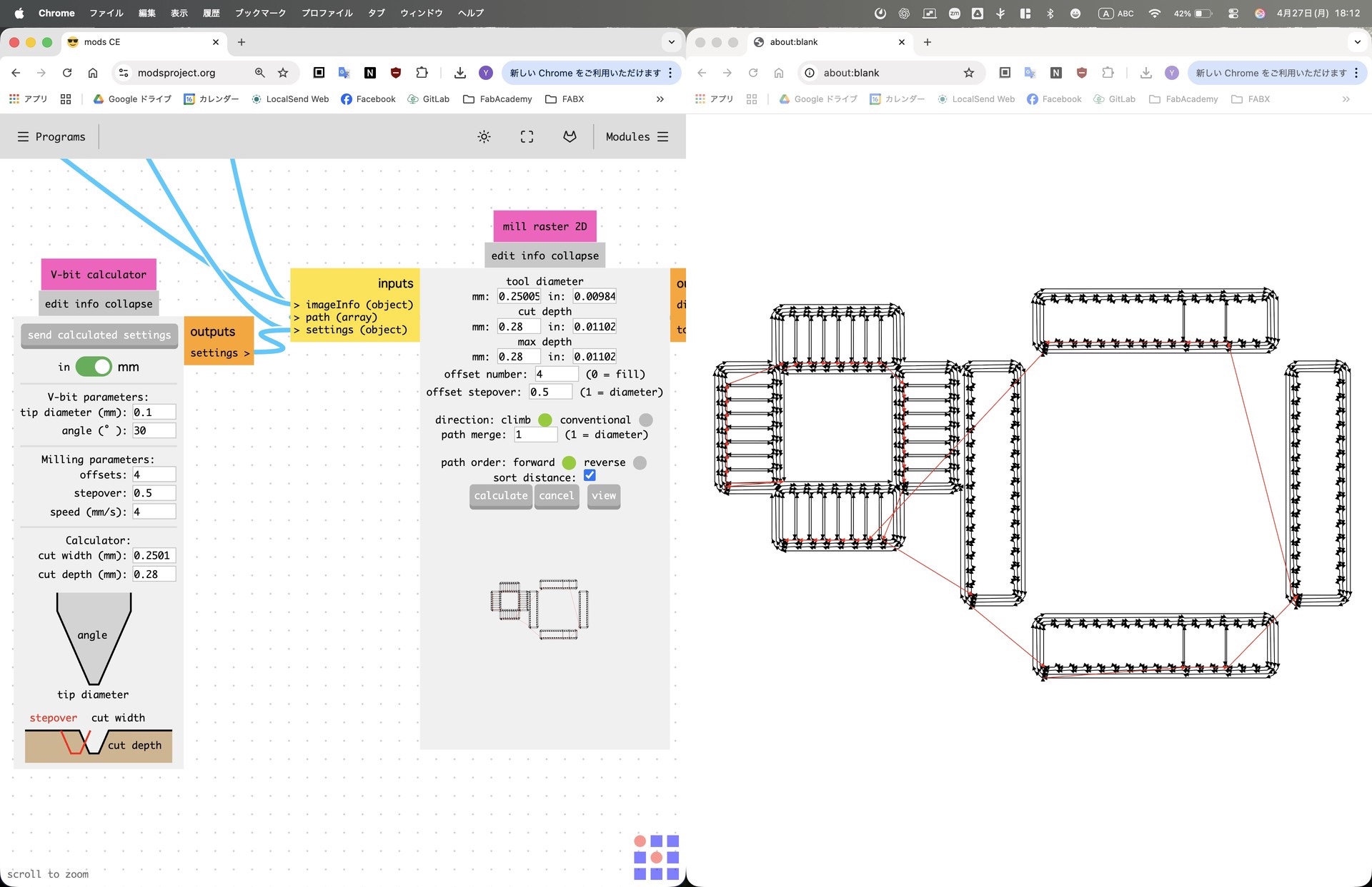
The ADS1292 I ordered that comes in the 32-TQFP package, which Yuichi reminded me to make sure is millable in our Genmitsu machine. As usual, I used Easytrace 5000, but worked with Yuichi to figure out the correct settings (that's why the image below is from MODS xD)
Just a note, I will be potentially using the XIAO's antenna to connect the glasses to my computer and the dashboard I created previously.
Milling the Board and Integrating it Within the Frame
The first time I milled the board I ruined it and the ADS1292 chip I had by being stupid in trying to remove the solder from the tiny 0.2 mm traces.
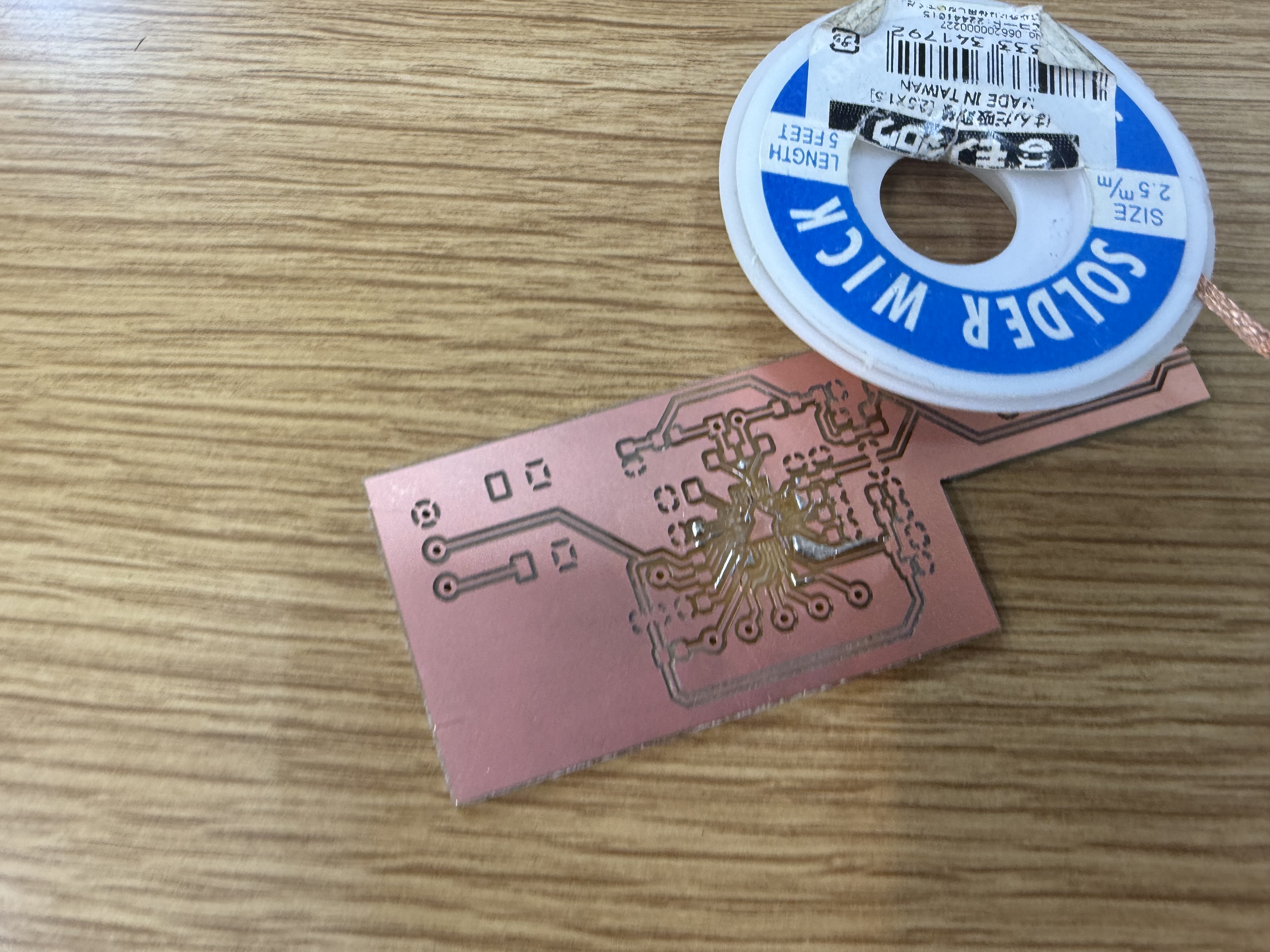
Later on, with a little guidance from Yuichi, I soldered everything properly.
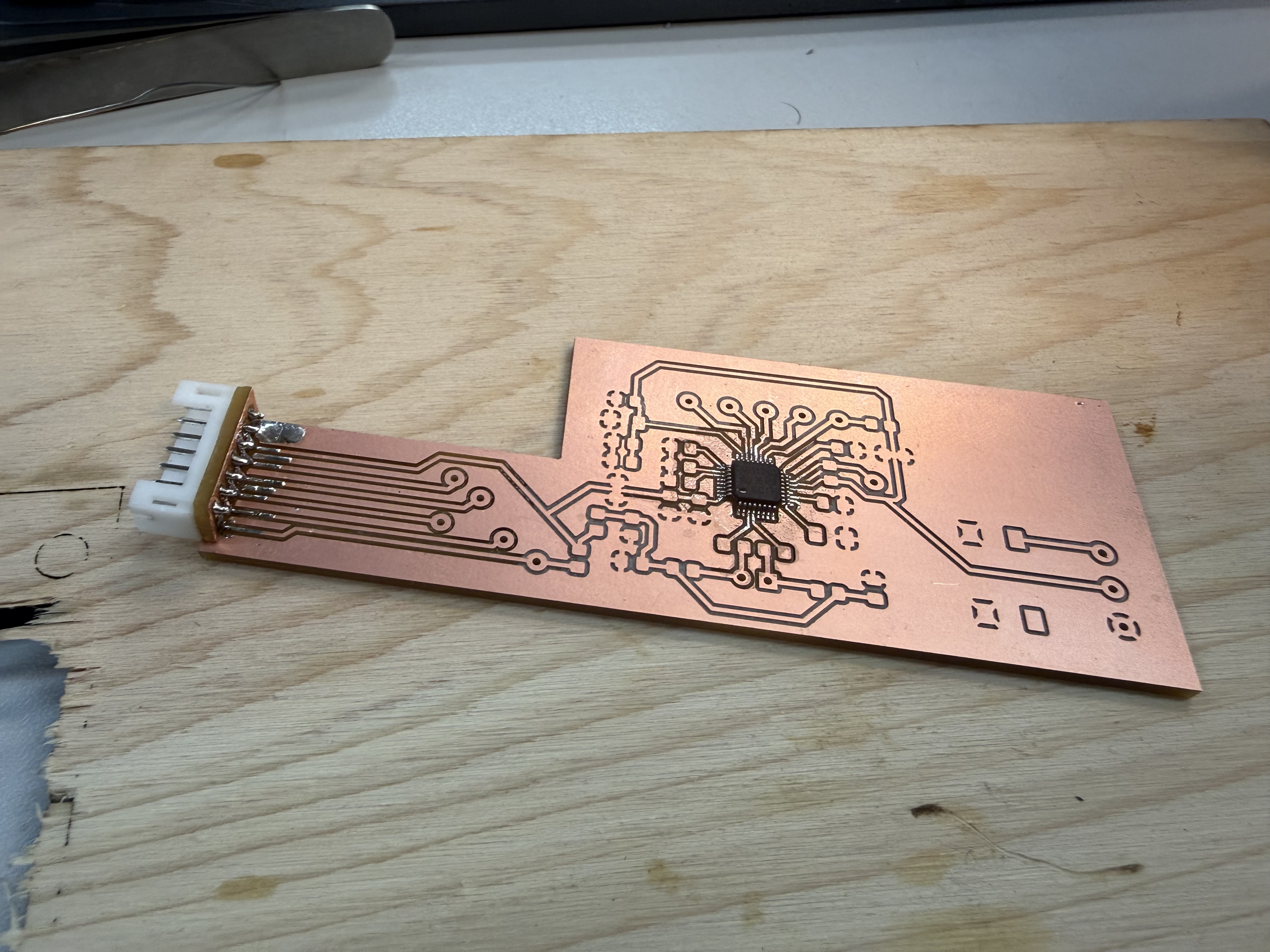
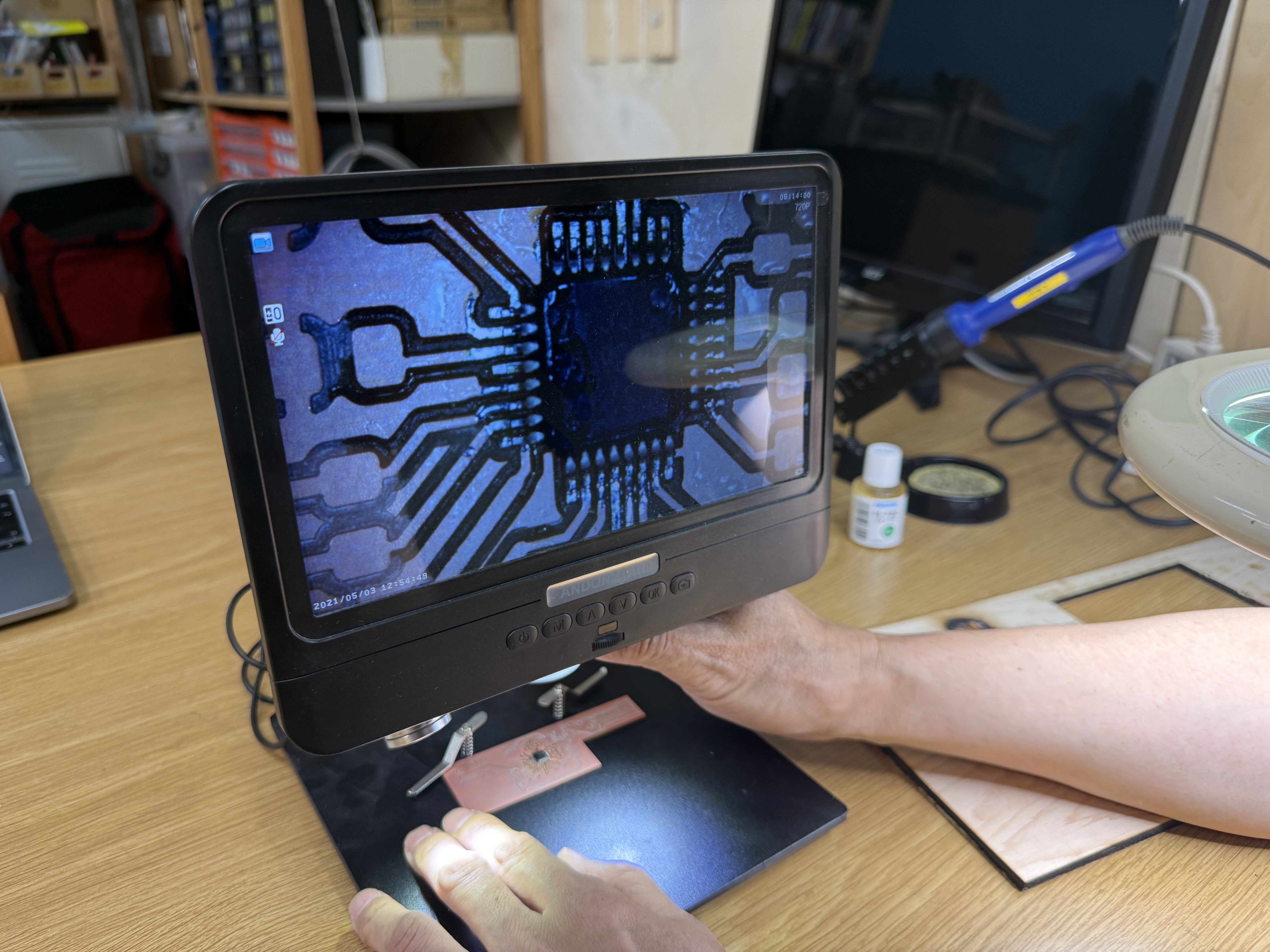
I soldered all the components and wired all the cables.
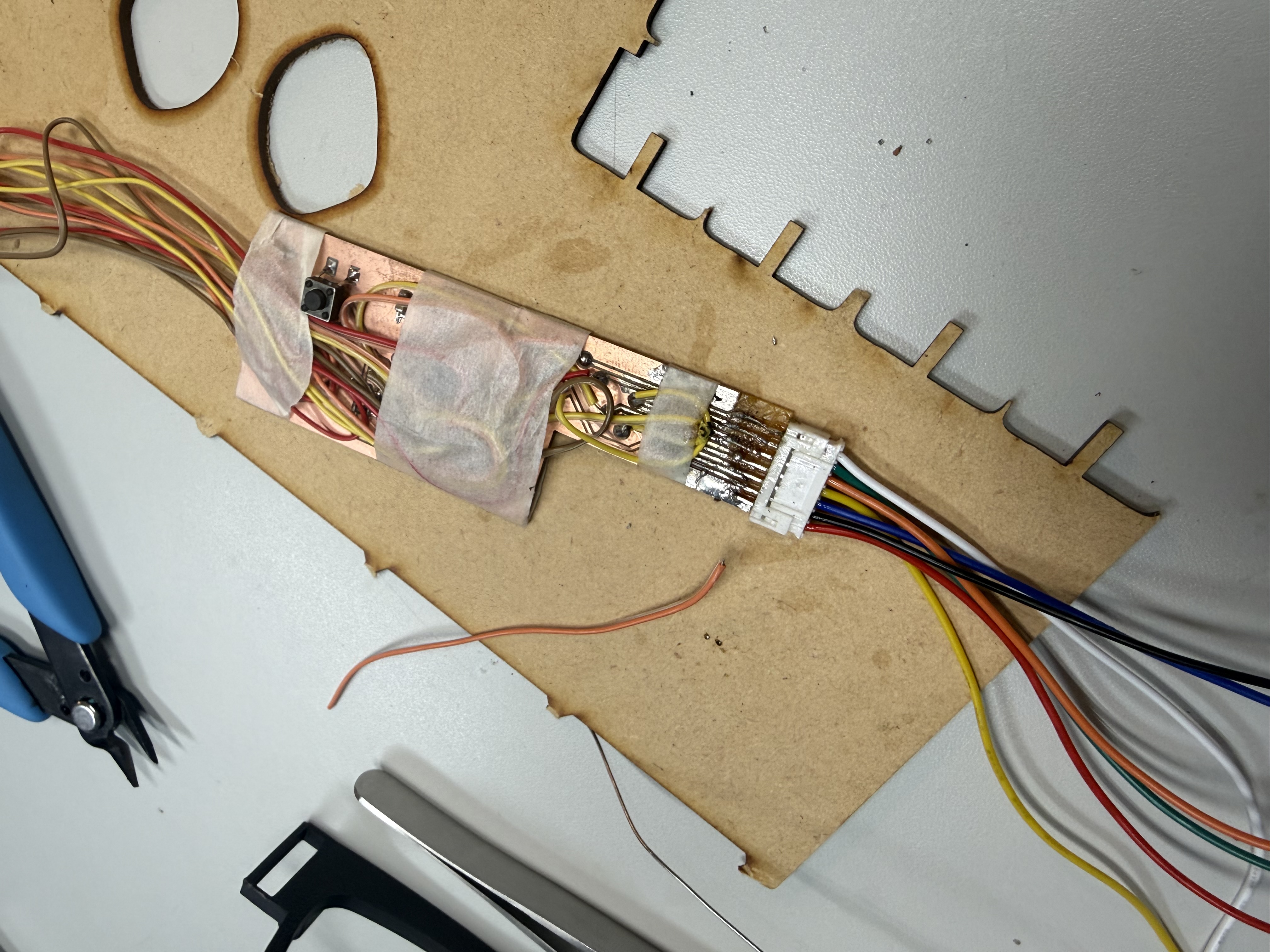
And it fit easily in the glasses' temples. ABSOLUTELY NOT, before this image and before soldering I needed to edit the design cuz of an issue I had in the calculations.
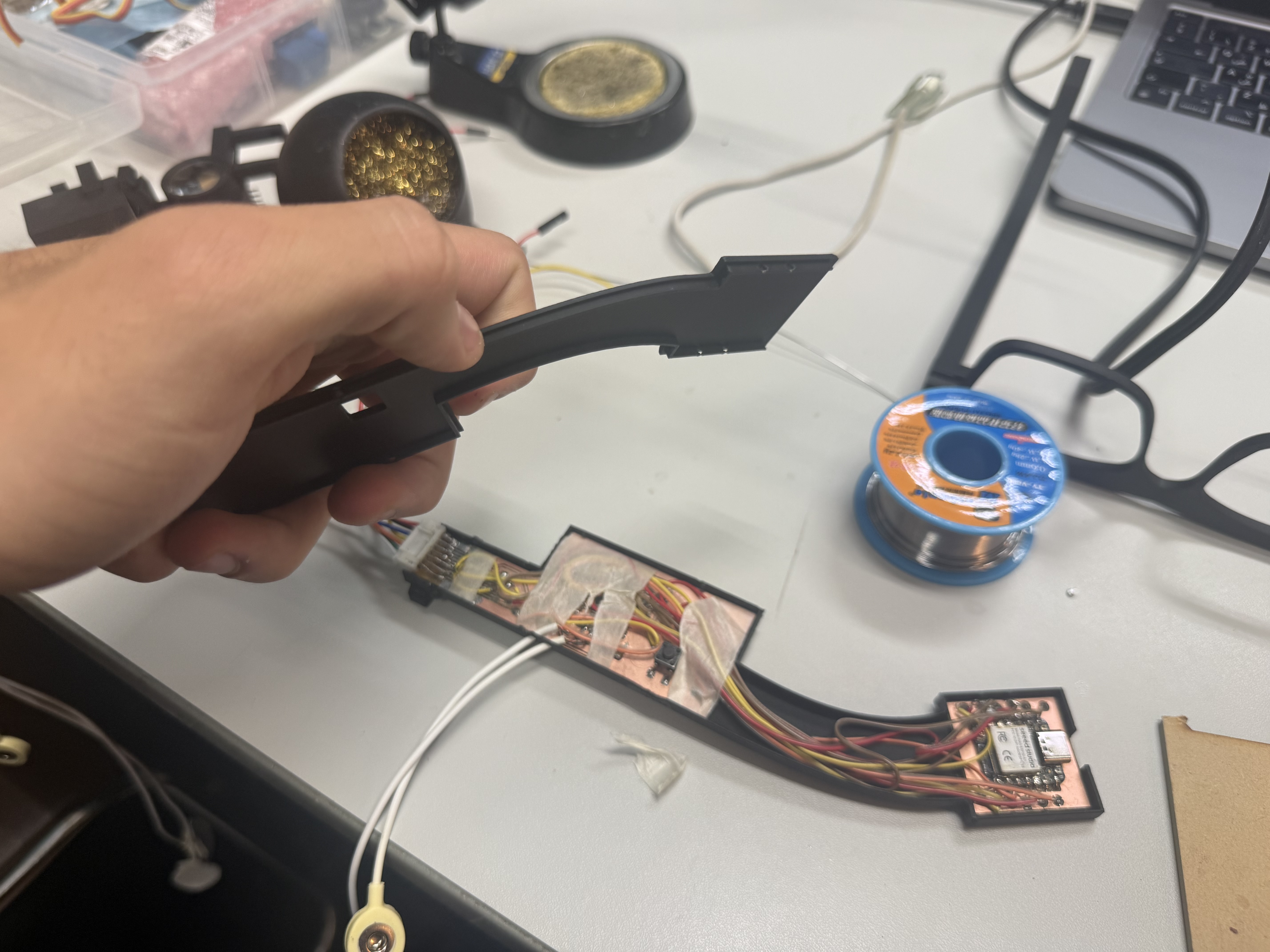
I know what you are thinking about the cables and how they look like spaghetti. I fixed that.
I received some feedback on that, so I properly modified the length of each cable and twisted them into bundles according to their location on the board. Here's how they look now:
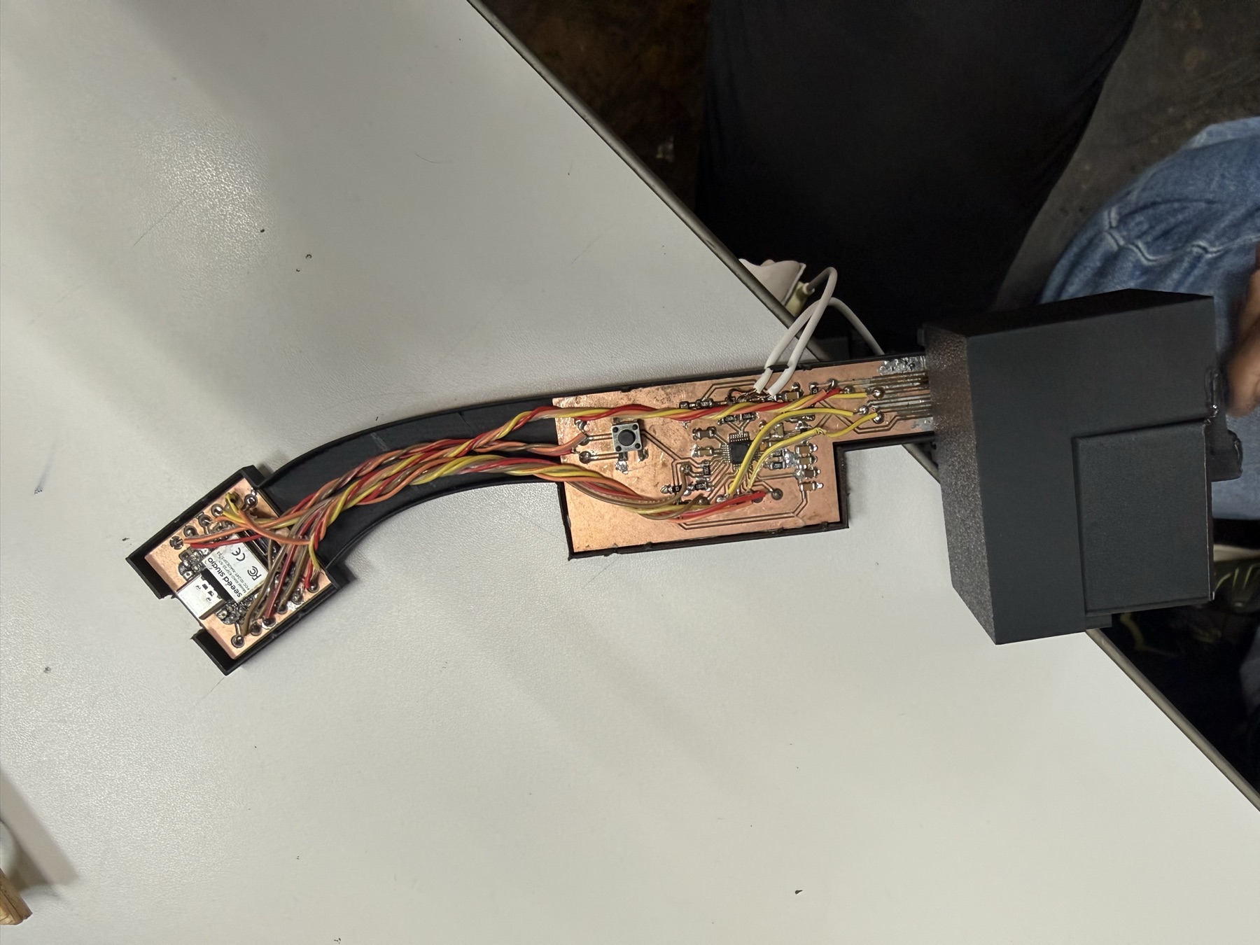
Final Packaged First Spiral
Here is how the glasses look on me:
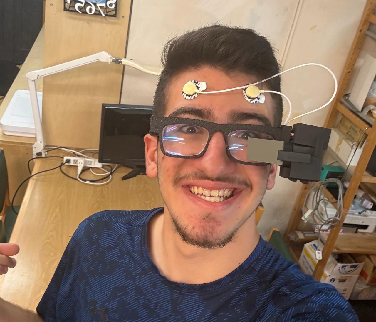
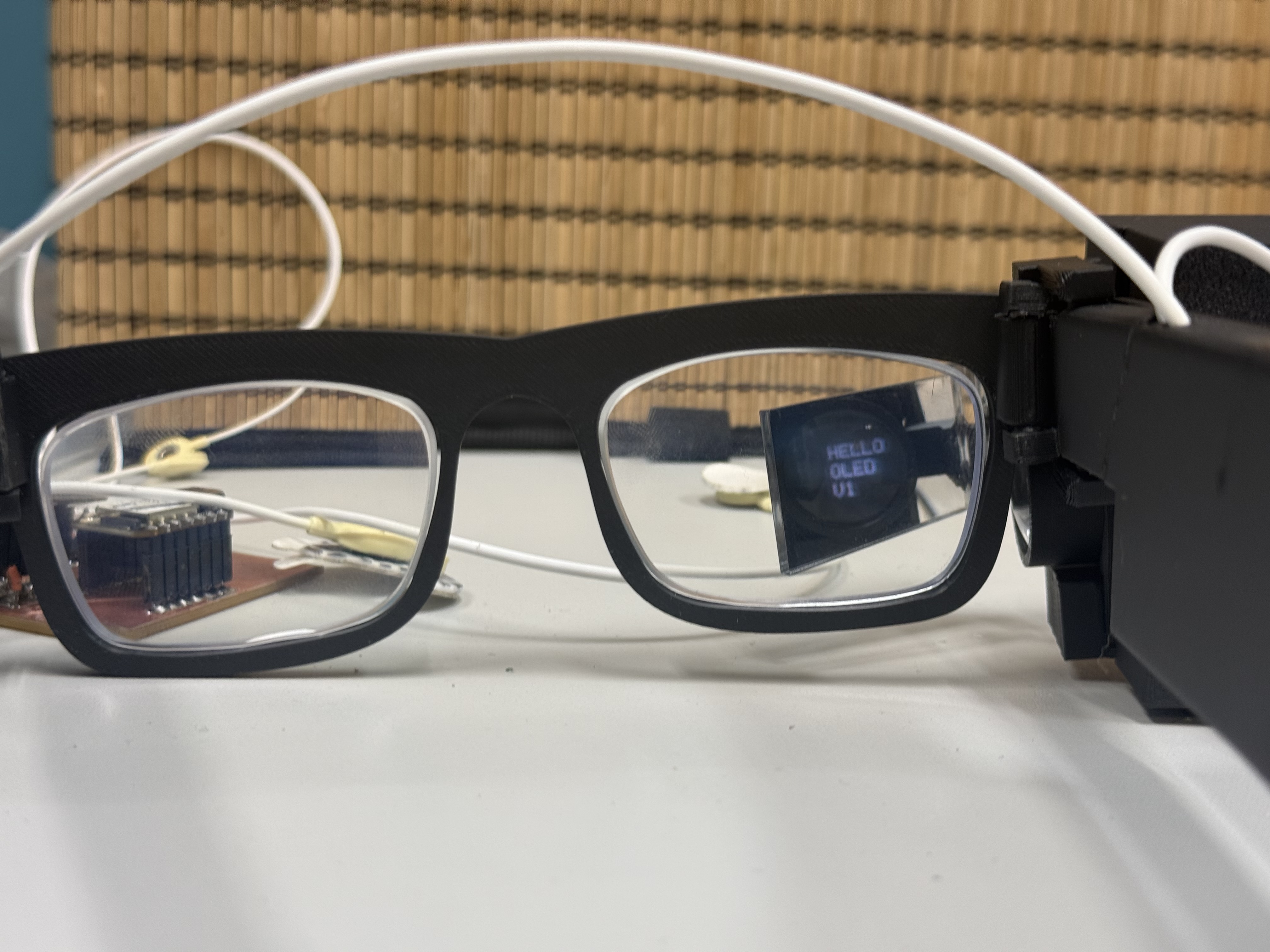
Here's how the display looks. You might think that this is too big of a mirror to be in-front of the eye, but I have it at a specific angle that will only reflect the lights coming out of the prism and convex lens into my eye.
Simultaneously, because of how our brain works and in a similar way to how you don't see your nose in-front of you, when you don't focus/look at the area the display is reflected, you can see everything in-front of you.
I will link the code in its relevant section. It was fully generated by codex and was specifically for demonstration purposes.
This is more simple text.
Honestly, for my upcoming spiral (the one I talk about below or the later ones I am working on), I will probably remove the color display since, while cool, it isn't really needed for the features I currently have.
I talk more in detail about this in my final project page, but now the plan as I finished my first spiral is to make the system more useful.
By testing and experimenting with what I built, I realized that the highest value thing I could do next is to utilize existing hardware and build this on top of it.
Here's what I mean. Instead of trying to put half-baked, "only works in a demo" features, I will be adding additional spirals.
Yes, Fab Academy's preaching all along, I might need to rephrase this later, but each step of the way is sort of its own spiral towards the final product.
I initially thought that once I get this spiral done, I would focus directly on adding new features to the same form factor.
However, I can actually add better, working features by integrating it with existing hardware like the Meta-Rayban glasses, which already has some features that would be beneficial to my final project.
This is an additional spiral I am adding (after the additional software tricks spiral I have to improve the EEG system), where I will have my system integrate with the Meta-Rayban Glasses with their newly released (more like newish) SDKs, and I am using them for this but my system could work for any of the other glasses.
Part of this parallel development is creating my own lightweight AI model to analyze the EEG signals and identify useful features from them. I am currently experimenting with SNNs for this.
I will be preparing my final repo to adapt to different types of smart glasses. I will talk more detail about this in my final project development log.
Original Designs and Code
This week's checklist
- Made a plan for system integration for your final project?
- Documented your plan with CAD and/or sketches for system integration?
- Implemented methods of packaging?
- Designed your final project to look like a finished product?
- Documented system integration of your final project?
- Linked to this system integration documentation from the final project development log.