Week 12 Machine Week
Click Here to Access the Group Project
X Axis Stepper Connector - McKinnon Collins
The group planned on using two steppers on the x axis.
I designed a board that connects both steppers to one input. By reversing the way the stepper is plugged in, you can change the direction that the stepper spins.
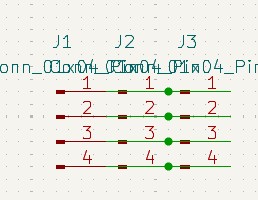
I added three, 1x4 connectors.

I assigned these footprints to the connectors.
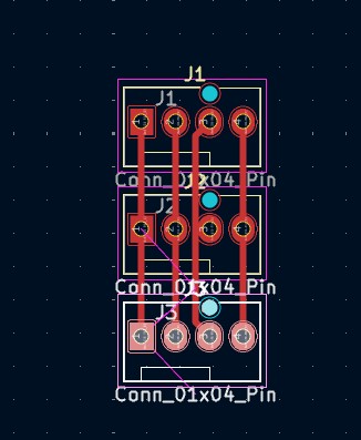
After the footprints, I entered the PCB editor. I oriented the connectors and then connected them with traces.
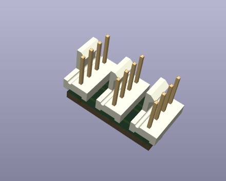
After connecting the connectors, I checked the 3d viewer to make sure everything looked correct.
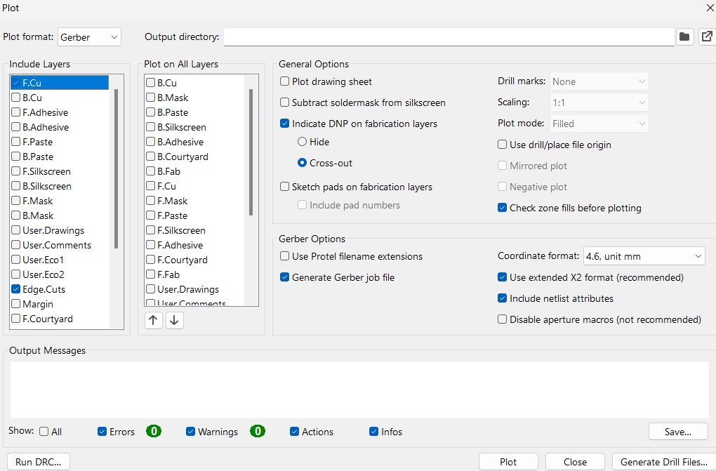
Once the board was correct, I generated the gerbers so the board could be milled. These are the settings I used to plot the gerbers.
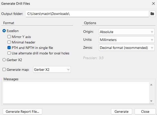
This board uses through holes, so I needed to make drill files. These are the settings I used to generate the drill files.
Files
You can access the Edge Cut Gerbers by clicking here
You can access the Front Copper Gerbers by clicking here
You can access the Drill file by clicking here
X axis, Y axis, and Machine - McKinnon Collins
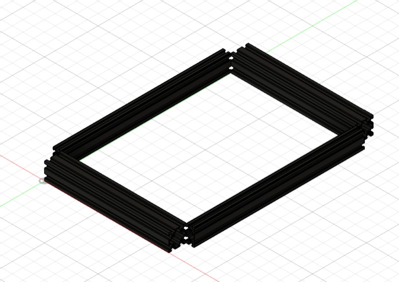
First, I added four aluminum extrusions as the base.
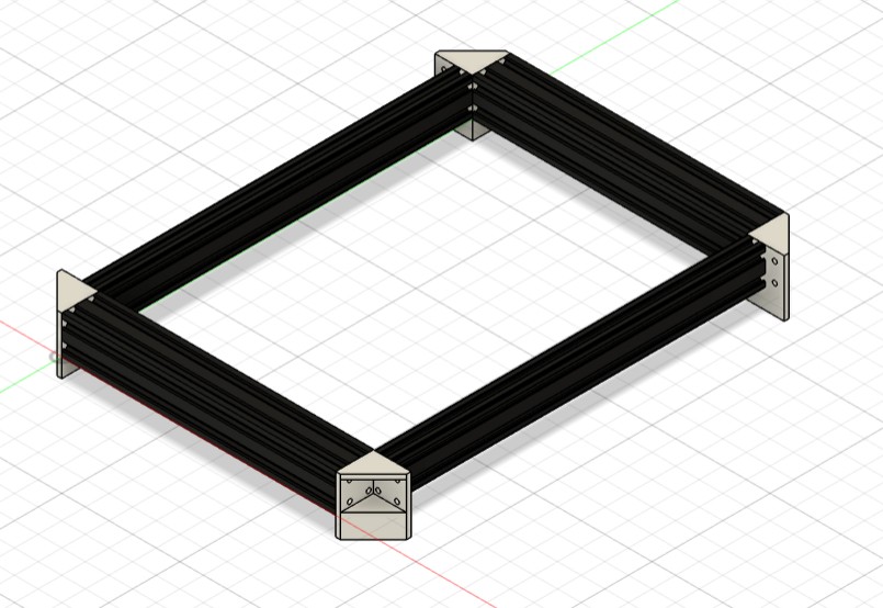
I then added some 90 degree connectors.
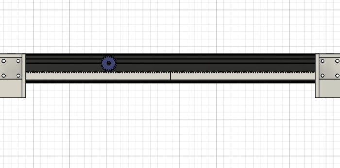
Next, I added a rack and pinion mechanism on both sides. This will be driving the X axis.
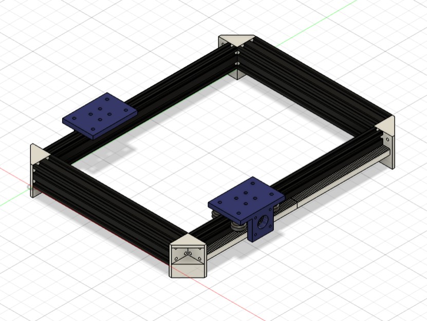
I then made a device that slides across the aluminum extrusion. It has a place for a stepper to be mounted that attached to the gear. It also has wheels so it can slide across the aluminum extrusion.
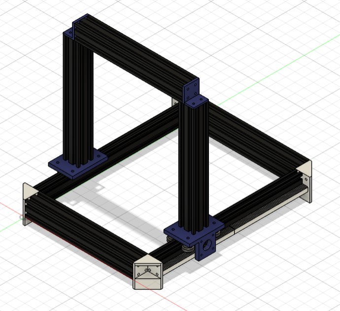
Next, I added some aluminum extrusions to house the Y axis.
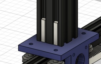
On those aluminum extrusions, I made some stoppers for the Y axis to rest on.
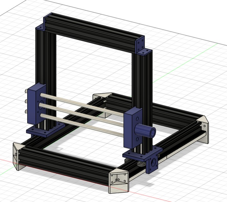
I made this Y axis mechanism. it uses a linear screw, with some linear guide extrusions. The middle bar is the linear screw. the outside ones are guide rails. I didn't thread the middle screw because I would not be fabricating it. A also added place for a stepper to attach.
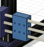
I recreated Ian's Y axis mount for visual representation.
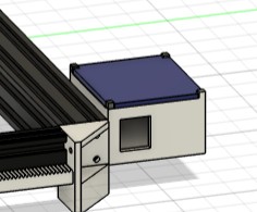
Lastly, I added space to house all the electronics.
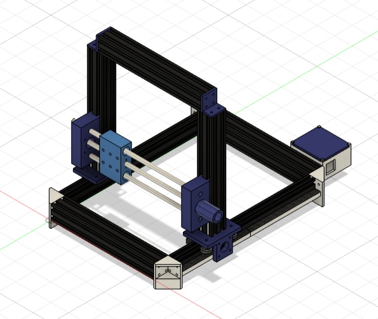
This is the final design.
Click Here to download the model as a .stl file
Machine Bed - McKinnon Collins
I decided to laser cut the machine bed out of Acrylic because it is strong, but still bends.
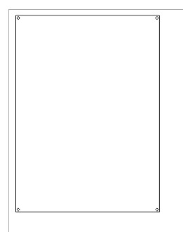
I made this sketch in Fusion 360 then imported it into Corel Draw so it could be laser cut.
Laser Cutting Settings
I used the Epilog Fusion Pro Machine. I used all the default settings.
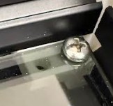
I then used these connectors that slide into the aluminum extrusions. As you can see, they hold up the machine bed, and attach to it with screws.
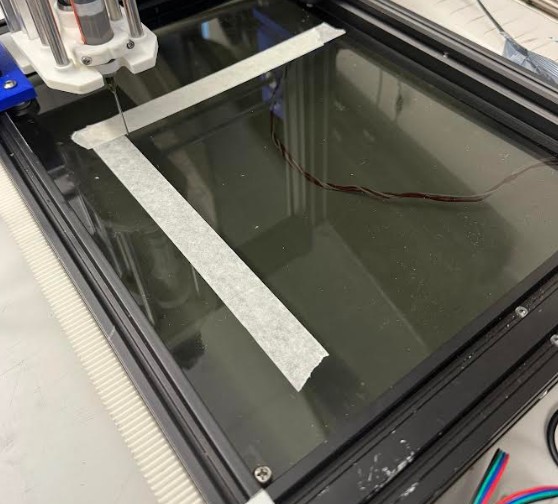
This is the bed on the machine. As you can see, the bed fits the machine well.