Machine Week
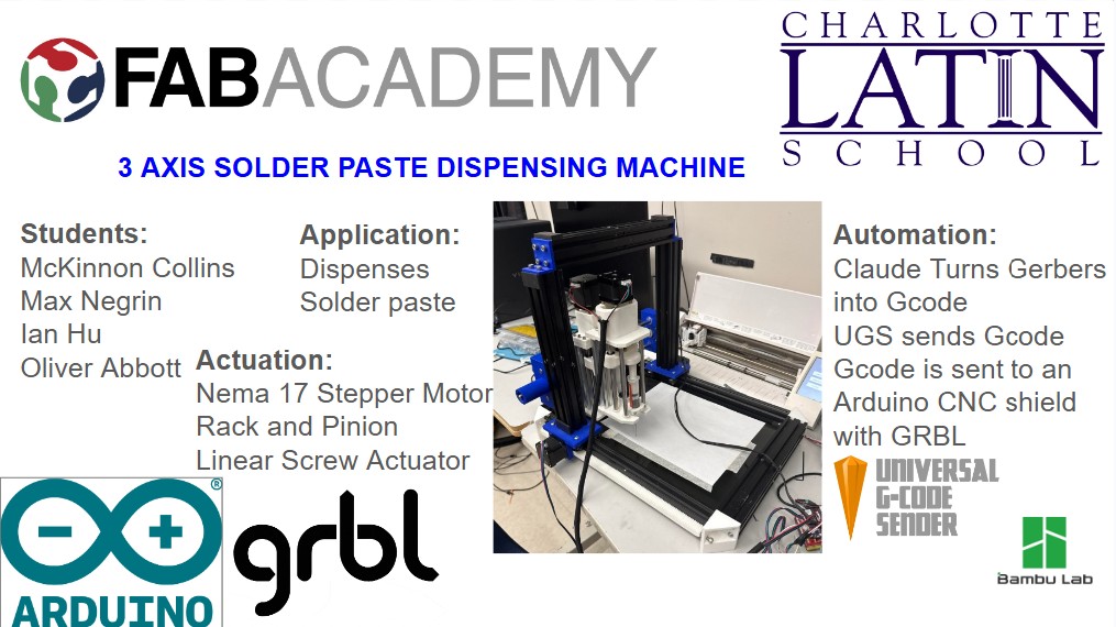
Our video for this week can be found on the home page of this site.
Programming the Stepper Motors - Yian and Max
For this part of Machine Week, we focused on getting our stepper setup working from zero. The whole idea was to go in order: hardware first, then firmware, then software control. We wanted to get to a point where we could connect and jog each axis manually without weird behavior.
Electronics Setup
We started by putting the motor drivers into the CNC shield. The main thing here was orientation. We made sure the enable pin side on each driver matched the enable marking on the shield before pressing anything down.

After that, we grabbed an Arduino, lined up the header pins, and pressed the shield into place. Then we connected the Arduino USB cable for upload/serial communication and wired our 19V power adapter into the screw terminals on the shield for motor power.

Before moving on, we quickly double-checked alignment and wiring. If a driver is rotated wrong or power is loose at the terminal, troubleshooting later gets confusing fast.

Firmware Installation (GRBL)
Once hardware looked good, we moved to firmware. We went to the GRBL GitHub repository, downloaded the master ZIP, and extracted it.
GRBL GitHub repository: https://github.com/gnea/grbl

Then we ran the GRBL upload flow, opened the upload sketch, and flashed it onto the Arduino. GRBL is basically what turns the Arduino into a CNC controller — it takes incoming motion commands and outputs step/direction signals for each axis.

After upload finished, the board was ready to receive CNC commands from host software.

Software Setup (UGS)
Next we set up the control software. We went to the UGS Platform GitHub page, downloaded the Windows .exe, and launched it.
UGS Platform GitHub page: https://github.com/winder/Universal-G-Code-Sender

Inside UGS, we selected the correct serial port and connected. That gave us a live interface to talk directly to GRBL.

Testing and Motion Check
After connecting, we manually jogged each axis in UGS. Jogging just means making small controlled moves one axis at a time so we can confirm direction and basic movement before running anything bigger.

This was our first full validation that the whole stack was working: electronics powered, GRBL flashed, UGS connected, and motion confirmed. Once we had this stable, we had a solid baseline for the next setup and calibration steps.

X Axis Stepper Connector - McKinnon Collins
The group planned on using two steppers on the x axis.
I designed a board that connects both steppers to one input. By reversing the way the stepper is plugged in, you can change the direction that the stepper spins.
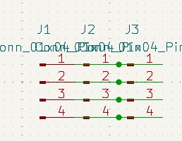
I added three, 1x4 connectors.
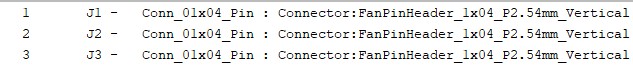
I assigned these footprints to the connectors.
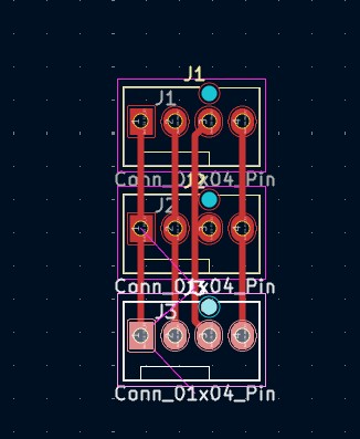
After the footprints, I entered the PCB editor. I oriented the connectors and then connected them with traces.
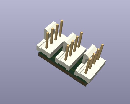
After connecting the connectors, I checked the 3d viewer to make sure everything looked correct.
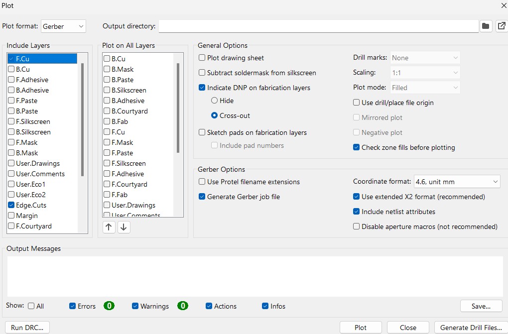
Once the board was correct, I generated the gerbers so the board could be milled. These are the settings I used to plot the gerbers.
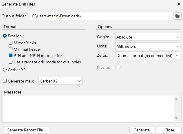
This board uses through holes, so I needed to make drill files. These are the settings I used to generate the drill files.
Files
You can access the Edge Cut Gerbers by clicking here
You can access the Front Copper Gerbers by clicking here
You can access the Drill file by clicking here
Y Axis - Ian Hu
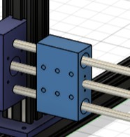
I designed a piece that can move back and forth on the Y axis.
This is the piece I designed.
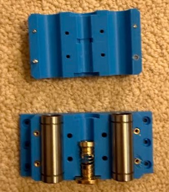
These are both pieces after printing. I added heat set inserts, linear bearings and the threaded piece so the machine can move back and forth on the axis.
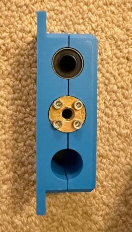
This is the side of the piece.
This is the piece on the Y axis.
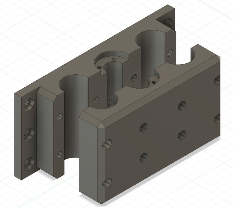
X axis, Y axis, and Machine - McKinnon Collins
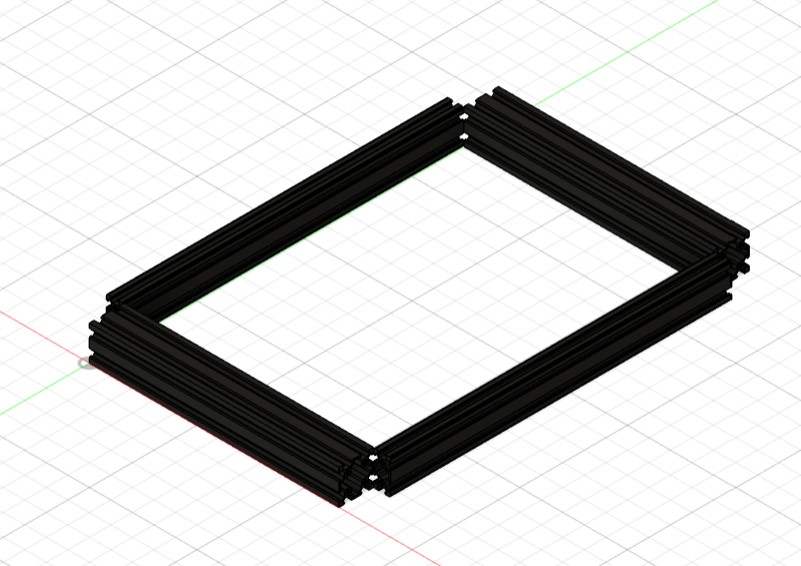
First, I added four aluminum extrusions as the base.
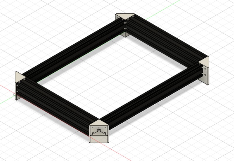
I then added some 90 degree connectors.
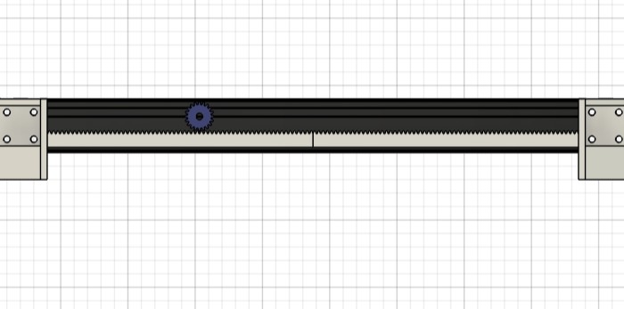
Next, I added a rack and pinion mechanism on both sides. This will be driving the X axis.
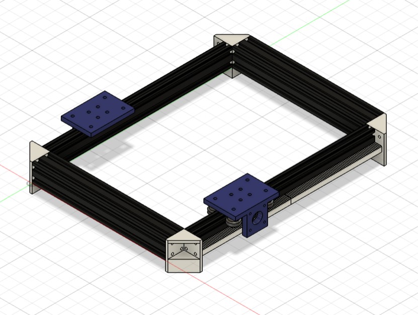
I then made a device that slides across the aluminum extrusion. It has a place for a stepper to be mounted that attached to the gear. It also has wheels so it can slide across the aluminum extrusion.
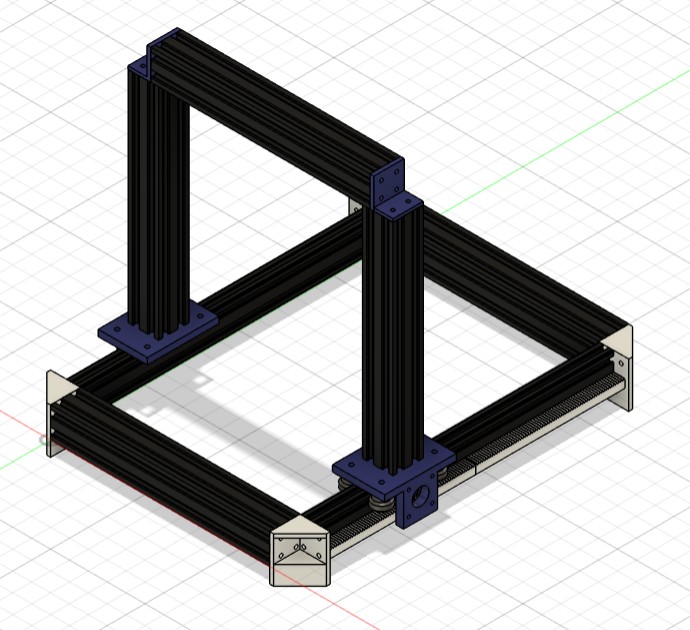
Next, I added some aluminum extrusions to house the Y axis.
On those aluminum extrusions, I made some stoppers for the Y axis to rest on.
I made this Y axis mechanism. it uses a linear screw, with some linear guide extrusions. The middle bar is the linear screw. the outside ones are guide rails. I didn’t thread the middle screw because I would not be fabricating it. A also added place for a stepper to attach.
I recreated Ian’s Y axis mount for visual representation.
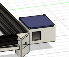
Lastly, I added space to house all the electronics.
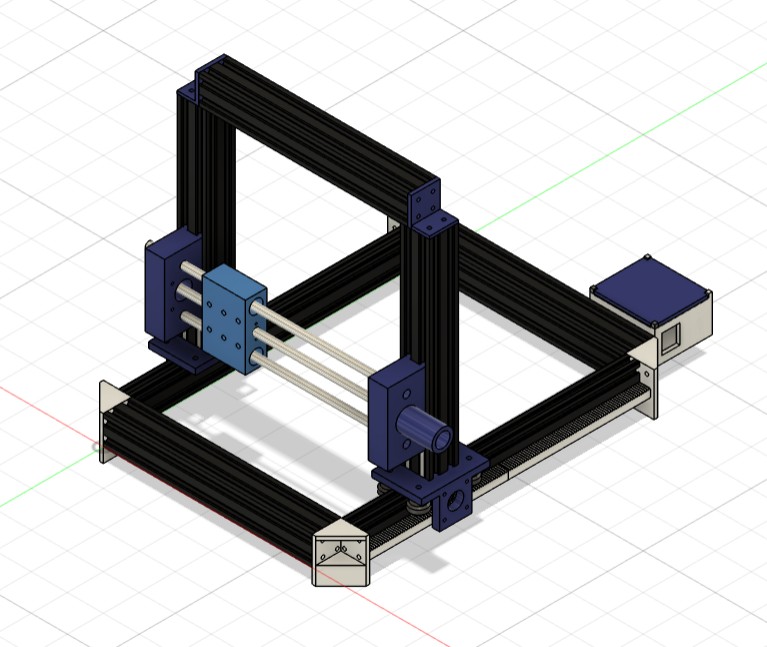
This is the final design.
Click Here to download the model as a .stl file
Machine Bed - McKinnon Collins
I decided to laser cut the machine bed out of Acrylic because it is strong, but still bends.
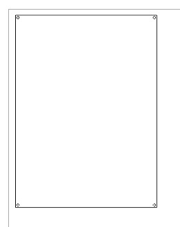
I made this sketch in Fusion 360 then imported it into Corel Draw so it could be laser cut.
Laser Cutting Settings
I used the Epilog Fusion Pro Machine. I used all the default settings.
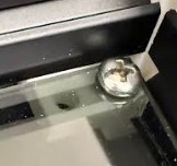
I then used these connectors that slide into the aluminum extrusions. As you can see, they hold up the machine bed, and attach to it with screws.
This is the bed on the machine. As you can see, the bed fits the machine well.
Click Here to download the file as a .dxf file
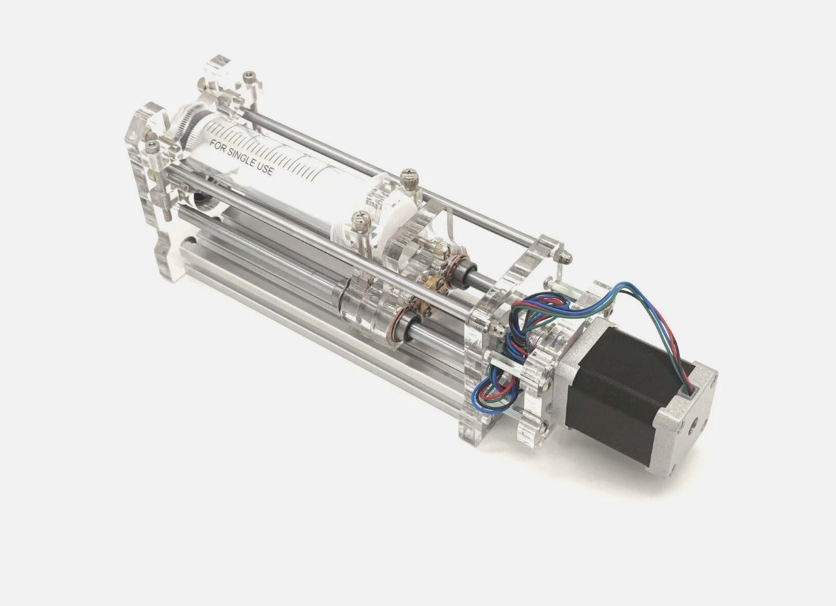
Tool Head & Z-Axis Design — Oliver Abbott
Click to expand Oliver's Tool Head & Z-Axis Documentation
3D Model — Interactive Viewer
Interactive 3D model viewer. Click and drag to rotate, scroll to zoom, right-click and drag to pan.
Assembled Machine
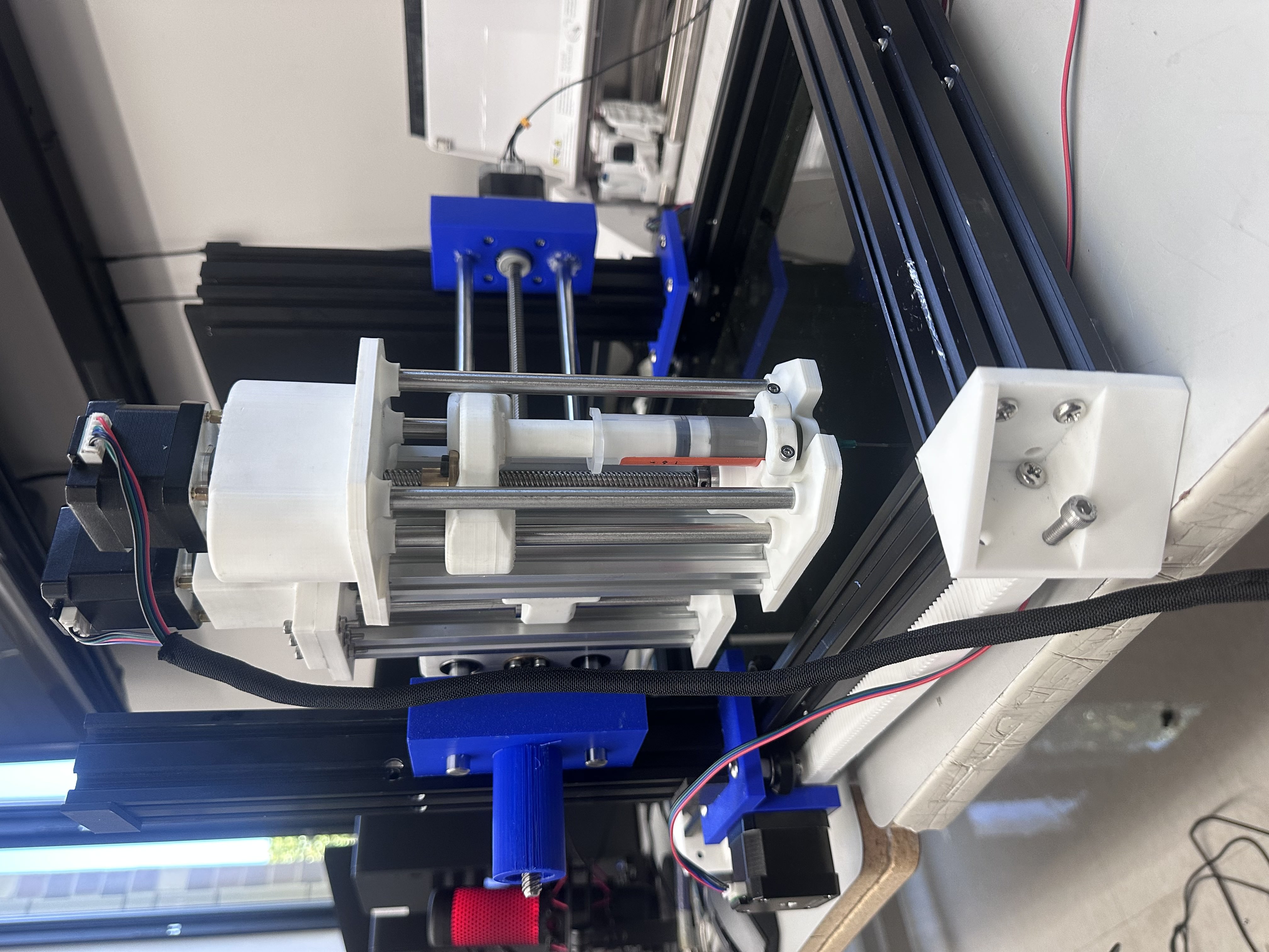
Assembly Chain
The assembly chain goes: tool head (syringe + dispense stepper) → Z-axis → Y-axis on the CNC gantry. My tool head mounts to the Z-axis, which then connects to the Y-axis carriage on the gantry that the rest of the team designed.
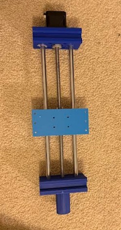
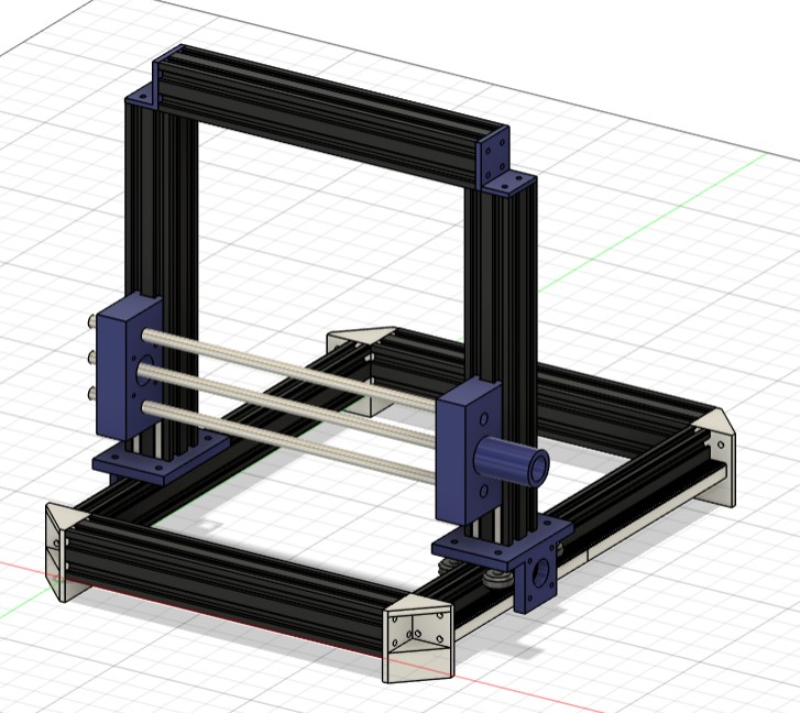
Z-Axis Mechanism
The Z-axis sits between two pieces of extruded aluminum, using two guide rods with linear bearings for smooth vertical travel and the same T8 lead screw as the tool head. The stepper motor turns the lead screw, which moves the entire tool head assembly up and down.
All the stepper motors on this machine are NEMA 17s, but for the Z-axis I needed a larger NEMA 17 — the Z-axis has to lift the entire weight of the tool head. The guide rods and bearings don’t carry any of the load; they only add rigidity and keep the carriage aligned. All the lifting force comes from the stepper motor and lead screw.
The Z-axis is configured the same way as the tool head — using extruded aluminum on the back for mounting. It works perfectly for vertical movement (up and down), and the mechanism is now fully functional and tested.
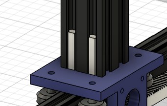
Stepper Motor Mounting — Redesigned
One of the harder parts was finding a strong way to mount the stepper motors, because they had to sit higher than the top plate. I had to design a mounting solution that held the motors securely above the plate while keeping everything aligned with the lead screw below.
I had a lot of trouble assembling the first motor mount design, so I redesigned it to make assembly much easier. The new mount is simpler and faster to put together. Unfortunately, during assembly I tightened one of the parts too much and it snapped — a piece is now stuck in the stepper motor. But it’s still pretty sturdy and will definitely work for what we need. The motor is secure and the Z-axis moves smoothly.
Limit Switch Considerations
We considered adding limit switches for homing and zeroing, but didn’t have time to implement them during machine week. The plan was to mount a limit switch on the tool bed (the surface where the PCB sits) rather than on the Z-axis itself. This approach would allow the machine to zero to the bed surface regardless of which syringe tip is installed, since different tips have different lengths. Mounting the switch on the bed would make the machine more versatile and ensure accurate Z-height calibration every time — something to add in future iterations.
Mounting to the Y-Axis
For connecting the Z-axis to the Y-axis, I told the team member responsible for the Y-axis that he would need to design his mount so the Z-axis could attach to the extruded aluminum — similar to how I mounted the tool head to the Z-axis using the aluminum extrusion. This kept the mounting approach consistent across the machine.
I designed the Y-axis mount to attach to the backside of the extruded aluminum. Initially, we had issues getting it connected — the parts weren’t lining up correctly. After I did some fixing and adjustments to his part, I was able to get it mounted up perfectly. The connection is now solid and the Z-axis moves smoothly along the Y-axis.
Cable Management
To keep everything clean and protect the wiring, I routed the motor cables through a cord protector (cable management sleeve). This gives the machine a much cleaner look and prevents the cables from getting caught in moving parts or snagging on the frame during operation. Proper cable management is critical on a CNC machine — loose wires can cause shorts, get pinched, or interfere with motion.
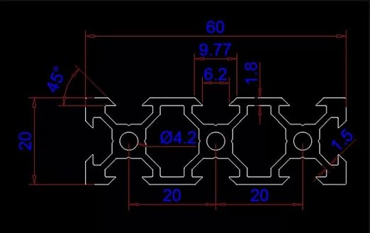
Aluminum Extrusion Mount
For the back of the tool head, I sourced an extruded aluminum profile from Amazon. This is what mounts the entire tool head assembly to the Z-axis. I sketched out the cross-section of the aluminum extrusion in Fusion 360 and extruded it to my desired length to model it accurately in the assembly.
Weight Considerations
The Z-axis assembly adds a lot of weight. I had to communicate to the rest of the team early on that the X and Y axes would need to be designed to hold significant weight without putting strain on their stepper motors. Getting that right early was important — if the frame can’t handle the load, nothing else matters.
Fastening & Assembly
For the 3D printed components, I used heat-set inserts to create strong, reusable threaded connections in the PLA parts. For the aluminum extrusion, I used a tap to cut threads into the inside of the extrusion channels, allowing bolts to thread directly into the aluminum for a solid mechanical connection.
Design Inspiration
Files
Programming - Max
I had a pretty straightforward task this week (or so I thought): to program. It was my job to actually make the motors move in the pattern we needed them to. I found that, by far, the hardest part of this week was getting the solder paste to extrude in the amounts that I needed. It was very difficult to get working, but I eventually got it, as you can see on the group site. I also ended up being the one to present it to the Fab Academy Zoom meeting to Neil, which was fun. This is how I did it:
In order to get the machine working, there were a few problems I needed to solve:
How would I send the GBRs to the machine?
How would I control the extruder axis if the CNC shield only supports XYZ?
How would I effectively control the amount of solder paste leaving the extruder?
Only #3 would prove difficult.
Starting with #1: We decided early on to use GRBL firmware paired with UGS (Universal Gcode Sender) to control the board, which we would ultimately use in the final product. Initially, I wanted to create a full‑stack gbr → pad positions → motor controls system using Claude, and cut out UGS as the middleman. This proved to be too difficult, so I had the idea to just generate GCODE and then have UGS send it to the CNC shield. To generate the GCODE, I simply had Claude create a toolpath generator from scratch. You import the front copper GBR and the program parses the file, renders the board, extracts the center of each pad, and enumerates them. Then it converts this set of pad coordinates to GCODE, with an optional offset, which I then open in UGS to send to the machine. There is a more detailed description of the software below.
With the GCODE software solving problem #1, now for #2. After researching the CNC shield and realizing it is simply a breakout board that connects power to stepper drivers, I realized I could use some of the unused pins to drive the A axis, which doesn’t have native control in the default GRBL firmware. So I used the grbl‑4thaxis GRBL fork, which uses a jumper between the Z‑axis limit switch and the A step/dir to control the A axis. However, grbl‑4thaxis enumerates this fourth axis as “E,” which I was able to easily change by tweaking the gcode.c file and then re‑flashing. With this problem out of the way, I could focus on the real challenge: the solder paste.
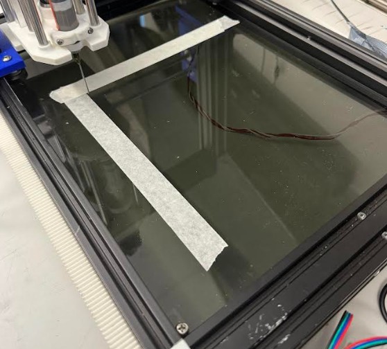
The solution I came up with for the extruder was this: before moving the X/Y to position, the extruder would move a predefined long distance, but since it wasn’t powerful enough to reliably move the plunger, it would instead exert force on the plunger for however long the pre‑load distance takes. This starts the cycle by getting the paste “flowing,” but is not actually long enough to extrude any paste. Now for the individual pad logic: after the gantry reaches the pad’s position (along the X/Y axes), the extruder starts pushing at the Z safe distance while the Z axis moves to zero position to get the paste where it needs to be. By starting the extrude at the top, I can raise the extruder when the tip reaches its position, releasing pressure and stopping more paste from flowing out. This results in a little bit of paste on the tip of the needle, which the gantry then rubs off by touching zero, actually going negative along the Z axis (which we can do because of our flexible work plate), then traveling half a millimeter, then lifting. Then it repeats that process for every pad, giving us solder paste on each one, albeit with questionable reliability. Personally, I believe this thing is definitely not anywhere close to viable in terms of using the machine or doing the paste yourself, but if we work on it I have confidence the process could be made trivial.
AI chat transcript
You can view my complete conversation with the AI here
Software Documentation (AI Generated)
paste-gen — software overview
You can download the entire software here
paste-gen is an offline host tool that turns a board layout into G-code for solder-paste dispensing on a 4-axis GRBL machine (XYZ + paste plunger). The application never connects to the CNC; it only writes a .gcode file. You stream that file with Universal G-code Sender (or any compatible sender).
What it does
You define where paste should go: draw rectangles, circles, and grids in the workspace, or import a KiCad paste-layer Gerber (.gtp / .gbp) so each pad is an editable shape. You set machine and process parameters in a profile (feedrates, syringe geometry, bed size, plunger axis letter, etc.). The app applies origin and offset rules so the layout maps to your fixture coordinates, orders the dispense moves, and emits G-code restricted to a known-safe subset for common 4-axis GRBL forks (e.g. gcobos/grbl4axis).
How to use it (conceptually)
- Configure and save a profile that matches your firmware and hardware.
- Build or import the paste pattern; adjust origin if needed.
- Generate and save G-code; fix any pre-flight warnings.
- Jog, home, and zero on the machine in UGS, then send the file.
For install, hardware, firmware, and a full walk-through, see the canonical guide in the repo, which you can download here
Here is a summary of key moments in my conversation with Cursor:
1. From “control the machine” to “only emit G-code”
Shift: The product stopped owning serial ports, jogging, and streaming; UGS (or any sender) became the runtime. The app’s job narrowed to layouts + profiles → validated .gcode.
Why it mattered: Clear separation of concerns, fewer failure modes in Python, and alignment with how GRBL workflows actually run in shops.
2. Travel vs dispense height — why things “vibrated” between pads
Shift: Bad or ambiguous Z behaviour between pads (not lifting to a consistent safe plane, or mixing modal states) produced violent-looking motion and noise.
Ah-ha: Paste jobs need an explicit safe travel Z between pads and a separate dispense height at the board; confusing them looks like “broken G-code” but is really motion policy.
3. Feedrate: travel must stay under firmware max
Shift: Travel feedrate was capped sensibly below $110/$111/$112-style limits; riding max feed on every rapid stalls steppers (“jackhammer”).
Ah-ha: Two numbers matter: ceiling (max feed, firmware) vs what you actually command (travel feed in generated G-code). Later this showed up again when max feed became editable in the Profile UI so warnings match reality.
4. Plunger bookkeeping — unretract is not “bonus paste”
Shift: After a retract, the next pad’s extrude move must prepend an unretract so paste actually flows; otherwise the move is “all prime, no dot.”
Ah-ha: cumulative_a / absolute plunger coordinates have to treat retract vs delivered volume differently; tests around sequence_builder lock this invariant in.
5. CAD-like workspace without losing Gerber truth
Shift: Shapes (rect/circle/grid) and Gerber import share a common notion of pads; origin picker + machine offsets fold into one transform pipeline.
Ah-ha: Keeping one coordinate pipeline (shape → machine → writer) avoids silent double-offset bugs.
6. DOT vs OUTLINE — paste vs troubleshooting traces
Shift: Outline mode traces perimeters without paste (dry moves), which is the right mental model for machine checkout — not “tiny dots in the middle.”
Ah-ha: Separate TraceOp / trace paths from DispenseOp so preview, stats, and G-code stay honest.
7. GRBL dialect discipline (and why G17/G94 vanished)
Shift: The writer deliberately emits a minimal modal subset so stripped Uno builds of 4-axis forks don’t choke on optional groups.
Ah-ha: “Valid-looking” CAM output can still alarm cheap forks; dialect tests encode the contract against the parser you care about (e.g. gcobos/grbl4axis).
8. The “E-axis error” was usually the wrong firmware — not your file
Shift: error:20 / unsupported words on plunger moves often meant stock 3-axis GRBL or a build without a fourth-axis letter — not a typo in paste-gen.
Ah-ha: $$ / $I tell you which interpreter you’re actually talking to; the fix is flash the intended 4-axis fork, then align axis_letter with what that build parses.
9. UGS “only likes A” vs firmware “E” — streaming vs jog UI
Shift: UGS jog widgets may favour certain axis letters, but streaming is generally word-agnostic if the firmware accepts those words.
Ah-ha: Some users patch firmware (e.g. E→A) for UI ergonomics; paste-gen supports extruder.axis_letter so generated G-code matches the flashed parser.
10. Dispense strategy — physics beats a single G1 E
Shift: dive_scrape adds real paste physics: preload at safe Z, coordinated dive (Z + large E), pressure relief, scrape shear, then lift.
Ah-ha: Net paste on the pad tracks planned + dive_extra − relief; preload is about column pressure and timing, not the same accounting bucket as calibrated pad volume.
11. Documentation became executable truth
Shift: docs/setup_guide.md replaced stale narratives as the canonical install/firmware/UGS path; older docs got explicit stale banners.
Ah-ha: When hardware and firmware forks diverge, one guide plus machine-checkable tests beats scattered markdown.
12. UX fit — tabs, scroll, and exposing max feed
Shift: Dense profiles don’t fit one viewport; tabs + scroll areas keep Motion/Dispense reachable. Max feed belongs beside travel feed because both drive realistic warnings.
Ah-ha: Configuration UX is part of safety — if users can’t see a field, they’ll cargo-cult defaults that don’t match $$.
This week was not as difficult as it was described to me by the upperclassmen. Although I had a pretty easy task for the project, I still tried to help wherever I could, in order to move the overall project forward. The programming was not an easy task, but not difficult. I used Cursor to help create a Gcode generator for GBR files, which takes a GBR as an input and outputs complete gcode, covering extrusion, preloading, and movement. This week taught me a lot about what goes in to controlling and designing these types of machines: what gantry system should you use (determined by load), what software, what hardware. It also made me think about PNP machines, and how I could potentially build a complete PNP machine (solder paste, component placing)
Reflection
Overall, the group finished the machine on time. Our programmer Max Negrin was able to figure out how to turn gerbers into an instruction for the machine. Because of this, we were able to present our machine to Dr. Gershenfeld and the rest of the Fab Academy. Because our machine is pretty physically complex, it took a long time for the machine to be physically complete. This put a lot of pressure on our programming team as they has little time to get the machine working.