11 - Networking
Group assignment:
- Send a message between two projects
Definitions
These definitions get pretty messy when you start taking into account the different layers of networking.
Bus address
A number that uniquely identifies a device on a shared communication bus, so the controller knows which device it’s talking to.
Network address
Networking people usually distinguish between two different kinds of addresses:
MAC address: Layer 2, physical/hardware address, only meaningful locally on the same LAN segment. Doesn’t survive routing. When a packet crosses a router to another network, the MAC address gets stripped and replaced with new ones for the next hop.
IP address: Layer 3, logical/network address, used to route traffic across networks globally. This is what most people mean when they say “network address.”
A common distinction is:
MAC addresses are hardware addresses, IP addresses are network addresses. They work as a team. The IP gets the packet to the right network, MAC gets it to the right device on that network.
We decided we would make a HTTP client/server One ESP32 runs a tiny web server, others send HTTP GET/POST requests to it. No laptop needed as broker. Simpler to understand conceptually, it’s just like a website on a chip. Works great for two boards but gets messier with many participants.
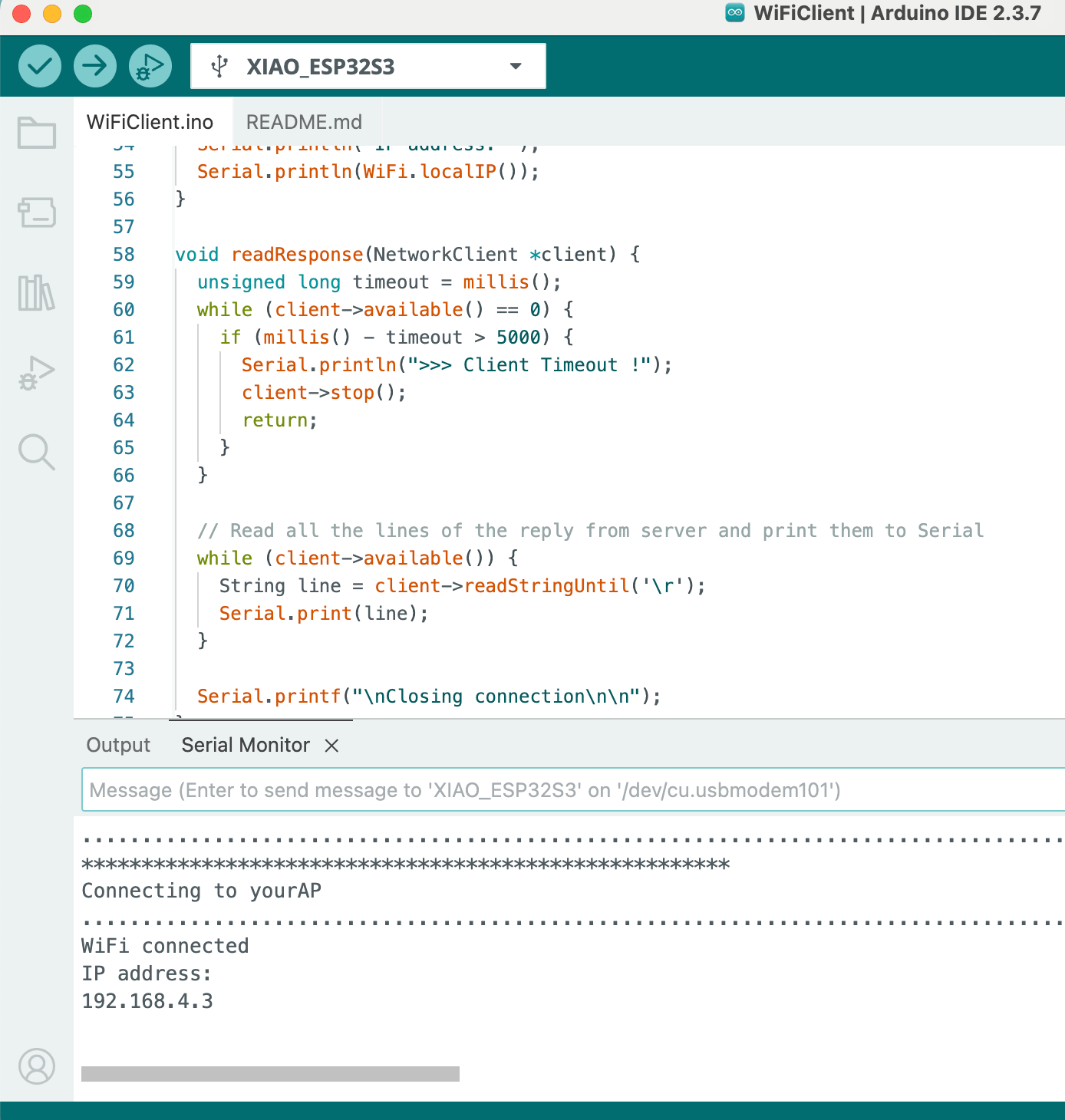
Screenshot courtesy of Claude…
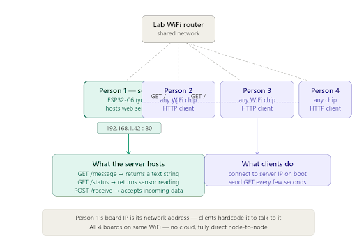
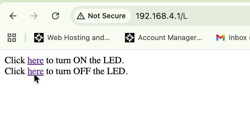
When an ESP32 is in AP mode it will have the default IP address of 192.168.4.1 and become a dhcp server that will hand out IP addresses in the 192.168.4.x range. If it is in the AP station mode the chip will get a local IP address from a dhcp server on the local network. That’s its network address. Clients hardcode that IP and just do GET /message every few seconds. The server can respond with whatever it wants, a sensor reading, a counter, a text string.
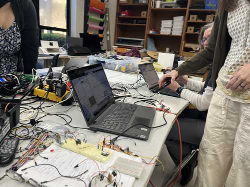
We set up our boards in the lab to our computers and started to code.
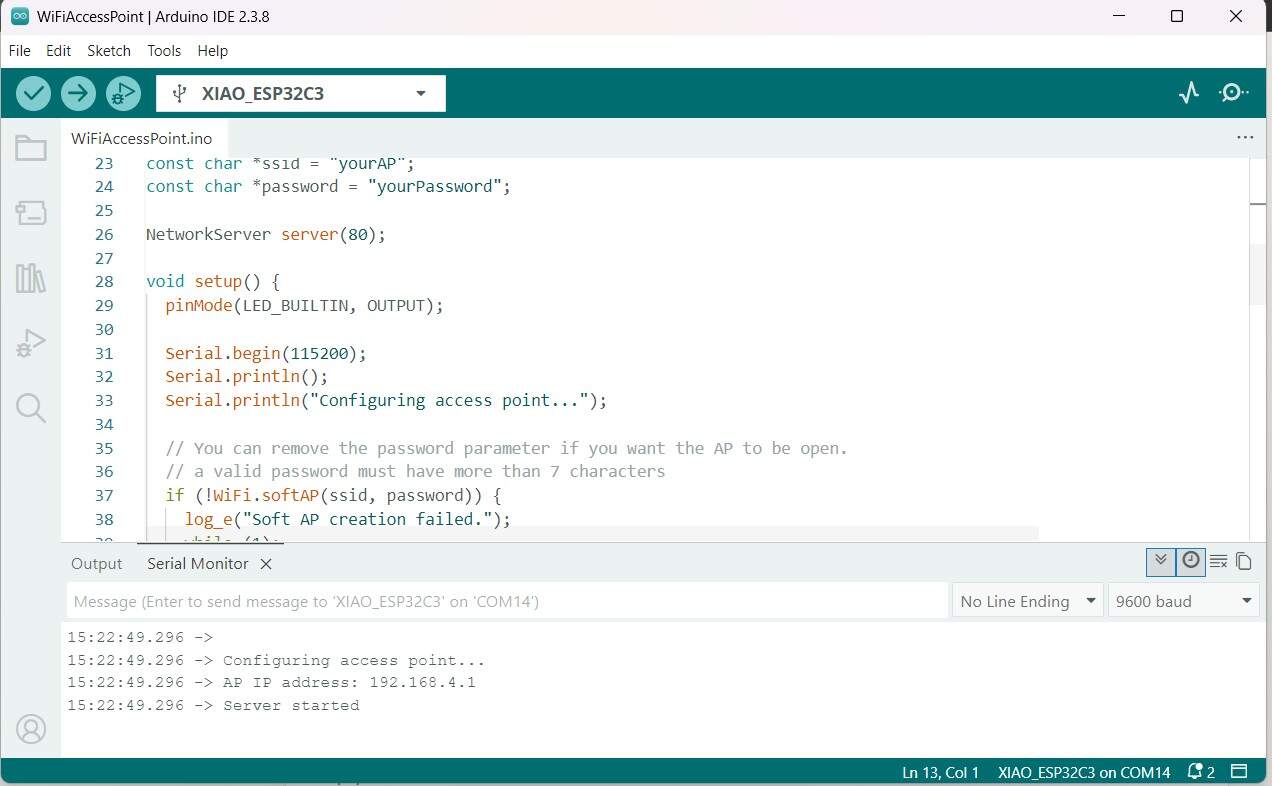
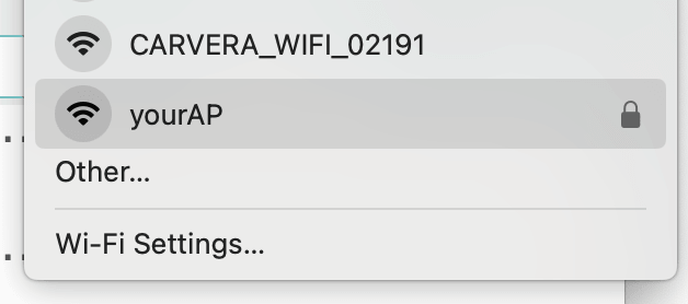
Camille loaded the example code for the ESP32C3 wifi Access Point. Which then broadcast the network onto Layer 2 on SSID - “yourAP”, and password “yourPassword”. Which started broadcasting “yourAP”.
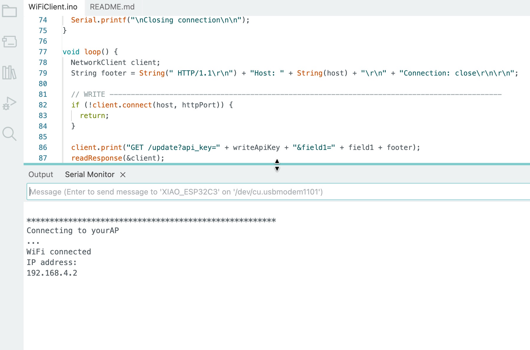
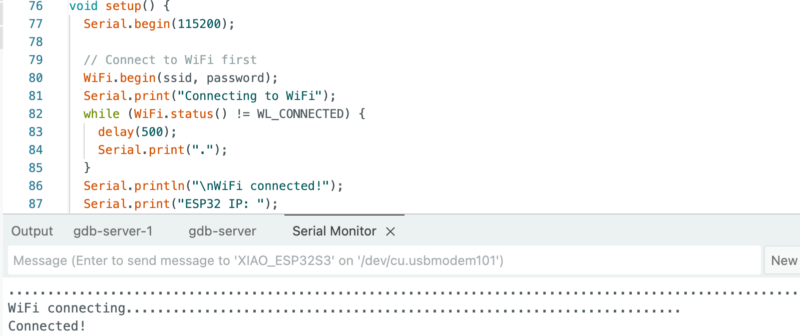
Kim uploaded the client example code for the ESP32C3 on her chip and then loaded the SSID and password from the access point into her chip. Then in the serial port we could see that we she was connecting to the first chip.
Dorian uploaded the client code as well and added her ESP32S3 to the mix and she connected
Then Angela uploaded the client code and added her ESP32S3 with OV3660 camera module to the mix and she connected.
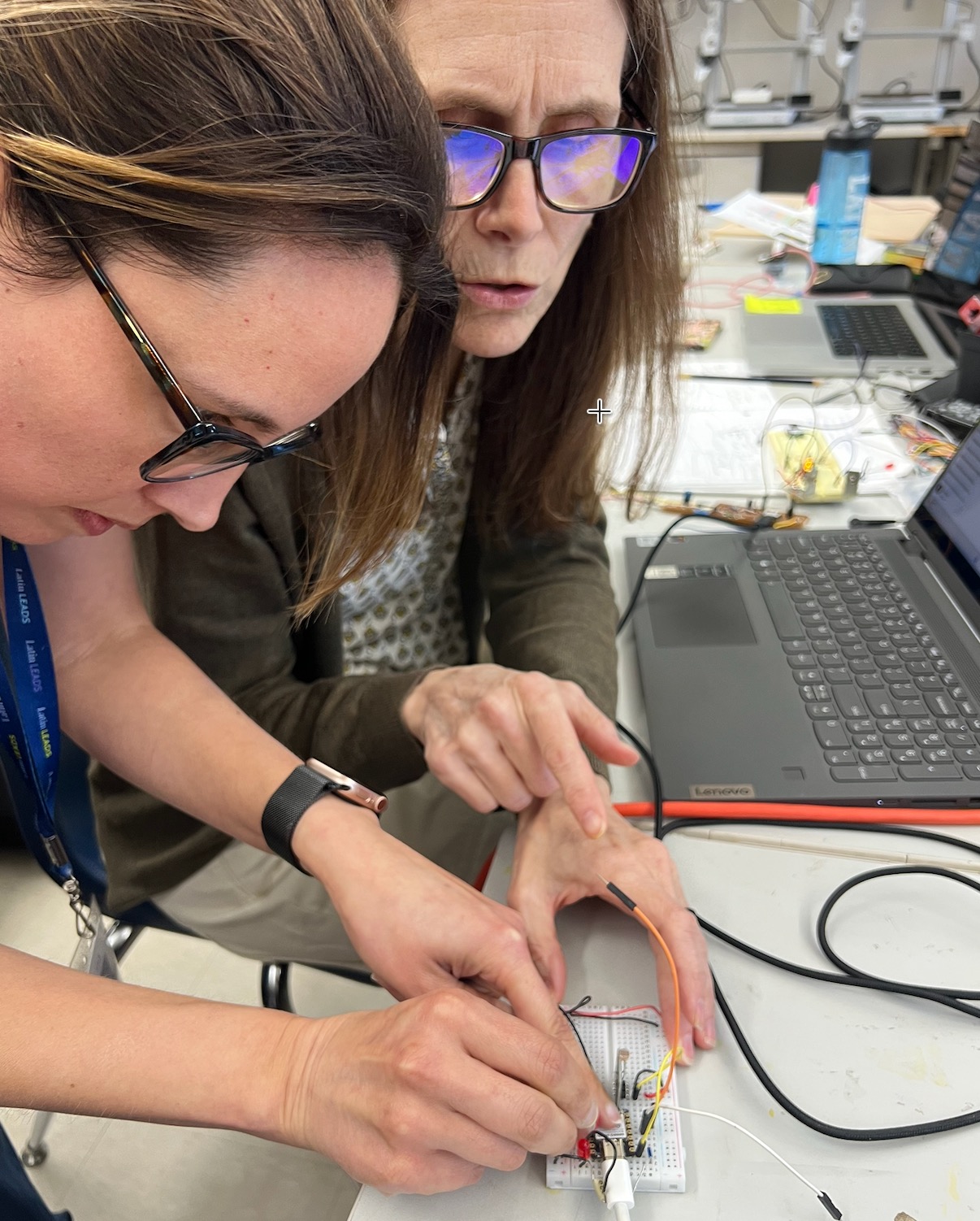 Now we have all 4 chips talking. Then we added Dorian’s Photoresistor as an input to Kim’s chip. The server chip had code in it that would serve up a webpage and let the user turn the light on and off using a click here command that sent TCP “GET /H” and “GET /L”.
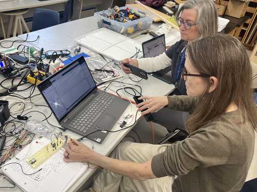 We changed the client code to send “ /H” and ” /L” based on the photosensor values and a set threshold of 500. Then we were able to put light on and off the sensor that would make the light on the server chip go on and off.
Then Dorian, Angela, and Kim were also able to use the webpage to turn the light on and off.
 See the video of the client light sensor controlling the light on the server chip.
Angela and Dorian connected to the chip with their computers.
See the videos of Angela and Dorian sending messages to the chip from the webpages they brought up on their computers connected to the chips broadcast to control the light.