Week 10 Output Devices
This week, we needed to measure the power consumption of an output device.
Measurment Device - Max Negrin
This week, we chose to use a multimeter to measure the power consumption.
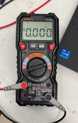
This is how we set up the multimeter for testing.
Output Device - McKinnon Collins
We chose to use a DC motor as our output device. Luckily, McKinnon Collins made a board that controls a DC motor with a potentiometer. This way, we can measure the power consumption of a DC motor at varying speeds.
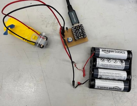
This is the board he made.
Testing - McKinnon Collins, Max Negrin, Yian Hu
When the motor turns off, that is when the multimeter is detecting how much current the DC motor is drawing. At low speeds, the motor was drawing around 1.5 Amps. At medium speeds, the motor was drawing around 2.8 Amps. And at high speeds, the motor was drawing around 3.5 Amps. The motor was using 5V. The total power consumption (in watts) is voltage x current (Amps). So overall, at low speeds, the motor was using around 7.5 Watts, at medium speeds, the motor was using around 14 Watts, and at high speeds, the motor was using around 17.5 Watts.
Reflection
The group found this week to be very easy. The assignment took little time to complete, as McKinnon Collins already created a suitible board. Measuring the power with a multimeter was very easy, however it took a 3 person team to record the test.
LED Batch Testing with Multimeter — Oliver Abbott
Full documentation on Oliver’s personal site — Week 10: Output Devices
For my contribution to the group work, I tested a batch of 20 through-hole LEDs (3mm, mixed colors) using a digital multimeter in diode mode to verify forward voltage (Vf) and identify any defective units before using them in a project.
Test Method
Each LED was tested individually by placing the red probe on the anode (longer leg) and the black probe on the cathode (shorter leg). In diode mode, the multimeter supplies a small test current — a healthy LED produces a forward voltage (Vf) reading and faintly illuminates. LEDs that showed OL (open loop) or abnormally low Vf were flagged as failed or marginal.
Expected Vf Ranges
| LED Color | Expected Vf |
|---|---|
| Red / Yellow | 1.8 – 2.2 V |
| Green | 2.8 – 3.1 V |
| Blue / White | 3.0 – 3.4 V |
Results — 16 Pass, 2 Marginal, 2 Fail
| # | Color | Vf (V) | Lit? | Status | Notes |
|---|---|---|---|---|---|
| 1 | Red | 1.84 | Yes | Pass | Normal |
| 2 | Red | 1.91 | Yes | Pass | Normal |
| 3 | Red | 1.88 | Yes | Pass | Normal |
| 4 | Red | 1.76 | Dim | Marginal | Below spec |
| 5 | Red | OL | No | Fail | Open circuit — dead |
| 6 | Yellow | 2.05 | Yes | Pass | Normal |
| 7–9 | Yellow | 1.98–2.11 | Yes | Pass | Normal |
| 10–13 | Green | 2.88–3.09 | Yes | Pass | Normal |
| 14–15 | Blue | 3.17–3.21 | Yes | Pass | Normal |
| 16 | Blue | 3.38 | Yes | Marginal | High end of range |
| 17–18, 20 | White | 3.08–3.14 | Yes | Pass | Normal |
| 19 | White | 0.43 | No | Fail | Shorted junction |
What I Learned
- Diode mode is the right tool: Supplies just enough current to forward-bias the LED without damage, and the Vf reading tells you immediately if the junction is healthy.
- 10% failure rate from bulk bags is normal: Always test before soldering — desoldering a dead LED from a finished PCB wastes time.
- Vf correlates with color: Forward voltage relates to the semiconductor bandgap energy which determines wavelength. Red ~1.9 eV (lower Vf), blue/white ~3.1 eV (higher Vf).