Networking and Communications
Goals
For the group work this week, we have to:
Send a message between two projects. - Max Negrin, McKinnon Collins, and Yian Hu
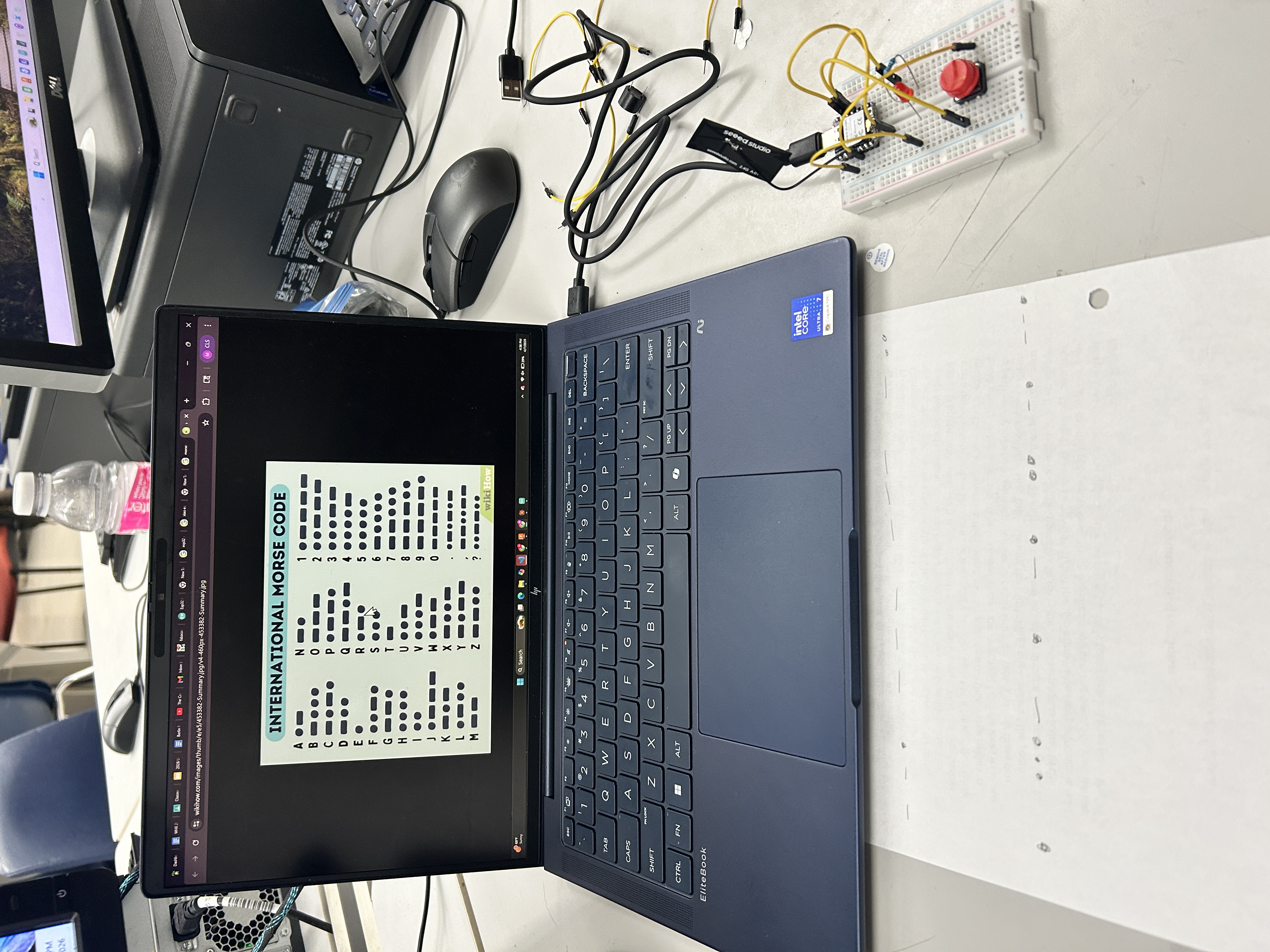
To complete the assignment, we will be designing a telegraph using LEDs, buttons, and two ESP32-c3’s. Pressing the button on one ESP32 will light up the LEDs of both ESPs, allowing for transmission of text via Morse Code. Firstly, I have to find a protocol to enable communication between the two devices. I will be using the ESP-NOW protocol, and will follow this tutorial to establish communication, and Claude to generate the actual script that triggers the LEDs.
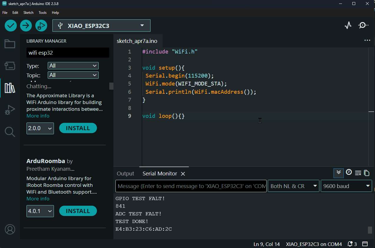
I used this script to find the MAC adress for each ESP32:
#include "WiFi.h"

void setup(){
 Serial.begin(115200);
 WiFi.mode(WIFI_MODE_STA);
 Serial.println(WiFi.macAddress());
}

void loop(){}
Then, I copied the MAC address from that MCU and put it in a google doc and labled it “1”. Then I ran it on the other ESP32, and also copied its MAC address. Now, with both of the addresses, I had Claude generate me the following script, which handles everything. You simply input the other ESP’s MAC address, and it will connect automatically. Then, when there is a signal in on the button’s GPIO, it sends a packet to the other ESP32 to tell it to light up its LED.
#include <WiFi.h>
#include <esp_now.h>

// --- Pin config ---
#define KEY_PIN   5    // Telegraph key (button), 3V3 to pin 5 (active HIGH)
#define LED_PIN   4    // LED, pin 4 to GND
#define BUZZ_PIN  6    // Buzzer, pin 6 to GND

// ESP 2's MAC address
uint8_t peerMAC[] = {0xE4, 0xB3, 0x23, 0xC6, 0xAD, 0x2C};

typedef struct {
  bool keyDown;
} TelegraphMsg;

TelegraphMsg outgoing;
TelegraphMsg incoming;
bool lastKeyState = false;

void onReceive(const esp_now_recv_info_t *info, const uint8_t *data, int len) {
  if (len == sizeof(TelegraphMsg)) {
    memcpy(&incoming, data, sizeof(TelegraphMsg));
    digitalWrite(LED_PIN, incoming.keyDown ? HIGH : LOW);
    digitalWrite(BUZZ_PIN, incoming.keyDown ? HIGH : LOW);
  }
}

void setup() {
  Serial.begin(115200);
  pinMode(KEY_PIN, INPUT_PULLDOWN);  // Pull-down since button connects to 3V3
  pinMode(LED_PIN, OUTPUT);
  pinMode(BUZZ_PIN, OUTPUT);
  digitalWrite(LED_PIN, LOW);
  digitalWrite(BUZZ_PIN, LOW);

  WiFi.mode(WIFI_STA);
  WiFi.disconnect();

  Serial.print("My MAC: ");
  Serial.println(WiFi.macAddress());

  if (esp_now_init() != ESP_OK) {
    Serial.println("ESP-NOW init failed!");
    return;
  }

  esp_now_register_recv_cb(onReceive);

  esp_now_peer_info_t peerInfo = {};
  memcpy(peerInfo.peer_addr, peerMAC, 6);
  peerInfo.channel = 0;
  peerInfo.encrypt = false;
  if (esp_now_add_peer(&peerInfo) != ESP_OK) {
    Serial.println("Failed to add peer");
  }
}

void loop() {
  bool keyDown = (digitalRead(KEY_PIN) == HIGH);  // Active HIGH

  if (keyDown != lastKeyState) {
    lastKeyState = keyDown;
    outgoing.keyDown = keyDown;
    esp_now_send(peerMAC, (uint8_t *)&outgoing, sizeof(outgoing));
  }

  delay(10);
}
Now that we got them connected to each other, we could start sending messages in Morse code. Mckinnon was sending me a message, and I had to decode it.
And here is another message, see if you can decode it.
Hive Monitor Pi — Networking Stack — Oliver Abbott
Full documentation on Oliver’s personal site — Week 11: Networking and Communications
Overview
For my individual networking assignment, I designed the full networking stack that lets a Hive Monitor Pi talk to the cloud — from first boot through steady-state telemetry. The device bootstraps, binds to a hive, and maintains persistent MQTT communication with AWS IoT Core.
I successfully connected to all my sensors (3× SHT45 temperature/humidity via I²C multiplexer), both cameras (Pi Camera Module 3 Wide on CSI ports), and my custom sensor extension board — all communicating over the network to the cloud backend via MQTT and HTTPS.
Architecture — 30-Second Picture
Pi (admin LAN, NAT'd)                      hive-monitor.com (AWS, us-east-1)
─────────────────────                      ─────────────────────────────────
hive-monitor-bootstrap.service ──HTTPS──▶  api.{dev.,}hive-monitor.com
(one-shot, until bound)               GET  /devices/{serial}/bind-packet
                                       POST /hives/bind        (manual path)

hive-monitor-agent.service ─────MQTT───▶  <account>-ats.iot.<region>.amazonaws.com
(steady-state)                        mTLS on 8883
                                      pub/sub on hive-monitor/hives/{hiveId}/*

hive-monitor-camera.service ────MQTT───▶  (same IoT endpoint, distinct MQTT session)
(only while a viewing session is active)
Three-Phase Lifecycle
Phase 1 — Bootstrap (Unbound)
hive-monitor-bootstrap.service runs at every boot while the device is unbound. It:
- Renames the host to
hive-monitor-<last-6-hex-of-cpu-serial>so a fleet of Pis each advertise unique mDNS names - Polls
GET https://api.hive-monitor.com/devices/<cpu_serial>/bind-packetevery 5 seconds:- 404 → device not claimed yet, keep polling
- 200 → bind packet received (cert, key, root CA, hive metadata). Install atomically, exit.
- Anything else → exponential backoff 10s → 300s (capped)
Phase 2 — Binding (Transition)
Two ways to bind:
- Fleet path (default): Operator claims the device in the dashboard, next poll returns 200 with the bind packet. Zero operator action at the Pi.
- Manual path: Operator SSHes in and runs
bind.sh --token <token> --region <region>
After binding, the device has its X.509 cert, private key, root CA, and hive configuration installed in /etc/hive-monitor/.
Phase 3 — Steady-State (Bound)
hive-monitor-agent.service connects to AWS IoT Core on TCP 8883 using mTLS with the per-device certificate. It then:
- Publishes telemetry (sensor data, weight, door/fan/LED state) every 60s
- Publishes health (CPU temp, RAM, disk, PoE voltage) every 60s
- Publishes events on change (provisioned, power_warning, etc.)
- Subscribes to commands (door open/close, LED override, camera start/stop)
- Uses Device Shadow for state sync
MQTT Topic Schema
All topics scoped to one hive via {hiveId} — the cert’s IoT policy enforces this.
Uplink (Pi → Backend):
hive-monitor/hives/{hiveId}/telemetry— sensor readings every 60s (QoS 1)hive-monitor/hives/{hiveId}/health— system health every 60s (QoS 1)hive-monitor/hives/{hiveId}/events— state changes on demand (QoS 1)hive-monitor/hives/{hiveId}/camera/{channel}/feed— H.264 frames (QoS 0, transient)
Downlink (Backend → Pi):
hive-monitor/hives/{hiveId}/door/command— open/close with request_idhive-monitor/hives/{hiveId}/camera/{channel}/control— start/stop streaminghive-monitor/hives/{hiveId}/ota/notification— new release announcement
Security & Auth
Three trust boundaries:
- Bootstrap — unauthenticated. Backend gates on operator claim.
- Bind — token-authenticated. One-shot 32-byte random token scoped to one hive.
- MQTT (steady-state) — mTLS with per-device X.509 cert. One cert can’t see another device’s traffic.
Firewall (ufw):
- Inbound: default-deny (SSH only if explicitly enabled at bind time)
- Outbound: allow 443 (HTTPS), 8883 (MQTT TLS), 123 (NTP), 53 (DNS). Everything else denied.
Offline Behavior
The Pi keeps operating while disconnected:
- Sensor reads, autonomous controllers, camera capture all continue normally
- Outbound publishes queue in SQLite buffer (
/var/lib/hive-monitor/buffer.db, 7 day / 500 MB FIFO) - On reconnect, buffered payloads replay at ≤50 publishes/s with original timestamps
- MQTT client retries connect forever with bounded exponential backoff — no outage requires operator intervention
How This Meets Assignment Requirements
| Requirement | Implementation |
|---|---|
| Wireless node with network address | Pi 5 on WiFi with DHCP IP + mDNS hostname hive-monitor-<id>.local |
| Local input/output devices | SHT45 sensors, cameras (input); door servo, fan, LEDs (output) |
| Networking protocol | MQTT 5 over mTLS (8883) + HTTPS (443) for bootstrap/bind/OTA |
| Communication between nodes | Pi ↔ AWS IoT Core — bidirectional via MQTT pub/sub + device shadow |
Group Work Contributions
I helped assemble the breadboard and wire up the parts for the group’s message-passing demonstration using ESP-NOW between two ESP32-C3s.