For my final project, I designed a custom PCB in KiCad to illuminate the beehive entrance for camera viewing. The board controls 7 LEDs wired in parallel, switched by a MOSFET, and controlled by a single GPIO pin from the Raspberry Pi 5.
Why Two Different LED Colors?
Each half of the hive entrance has a Raspberry Pi Camera Module 3 Wide mounted to observe bee activity. To see the bees clearly, the entrance needs lighting — but there's a catch: I need to observe the bees at night without disturbing them.
This is where bee vision comes in. Honeybees see light differently than humans. Their visual spectrum ranges from about 300nm (ultraviolet) to 650nm (orange), which means they can see UV light that we can't, but they cannot see red light. Red light has a wavelength of approximately 620–750nm, which falls entirely outside the bee's visible range. To a bee, a red LED might as well be off — they simply don't have the photoreceptors to detect it.
Bees have three types of photoreceptors: one peaking in the UV range (~340nm), one in blue (~430nm), and one in green (~535nm). Notice there's no receptor anywhere near the red end of the spectrum. This is why beekeepers have long used red headlamps when inspecting hives at night — the bees remain calm because they literally cannot see the light.
White LEDs, on the other hand, emit a broad spectrum that includes blue and green wavelengths — both of which bees can see clearly. White light would agitate the bees at night, disrupting their rest cycle and potentially triggering defensive behavior.
So the solution is two boards per entrance half:
- White LED board: Used during daytime viewing when the bees are already active and ambient light is present. The white LEDs supplement natural light for clearer camera footage.
- Red LED board: Used during nighttime viewing. The red light illuminates the entrance for the camera (which can see red light just fine) without disturbing the bees at all.
The Raspberry Pi determines whether it's day or night and activates the appropriate board when the cameras turn on. In total, I need 4 boards — 2 white and 2 red (one of each per entrance half).
Circuit Design
I designed the board in KiCad. The circuit is simple but effective:
- 7× 3mm LEDs wired in parallel, each with its own current-limiting resistor
- N-channel MOSFET on the low side to switch all 7 LEDs on/off
- 10kΩ pull-down resistor from the MOSFET gate to ground — this ensures the LEDs stay OFF when the GPIO pin is not actively driving the gate (e.g., during Pi boot-up or if the GPIO is floating). Without the pull-down, the gate could pick up stray voltage and turn the LEDs on unexpectedly.
- Gate resistor between the GPIO pin and the MOSFET gate to limit inrush current to the gate capacitance
The entire board is controlled by just 3 wires:
- Power (VCC): 3.3V or 5V from the Pi (depending on LED forward voltage requirements)
- Ground (GND): Common ground with the Pi
- GPIO signal: A single GPIO pin from the Pi drives the MOSFET gate — HIGH turns the LEDs on, LOW turns them off
Power Consumption Calculations
White LED Board (×2):
- Typical 3mm white LED: forward voltage (Vf) ≈ 3.0–3.2V, forward current (If) = 20mA
- Running from 5V supply with a current-limiting resistor per LED
- Resistor value: R = (5V − 3.1V) / 20mA = 95Ω → use 100Ω resistor
- Actual current per LED: (5V − 3.1V) / 100Ω = 19mA per LED
- Power per LED: 5V × 19mA = 95mW per LED
- Per board (7 LEDs): 7 × 19mA = 133mA, 7 × 95mW = 665mW per board
- Both white boards: 266mA total, 1.33W total
Red LED Board (×2):
- Typical 3mm red LED: forward voltage (Vf) ≈ 1.8–2.0V, forward current (If) = 20mA
- Running from 3.3V supply with a current-limiting resistor per LED
- Resistor value: R = (3.3V − 1.9V) / 20mA = 70Ω → use 68Ω resistor (standard value)
- Actual current per LED: (3.3V − 1.9V) / 68Ω = 20.6mA per LED
- Power per LED: 3.3V × 20.6mA = 68mW per LED
- Per board (7 LEDs): 7 × 20.6mA = 144mA, 7 × 68mW = 476mW per board
- Both red boards: 288mA total, 0.95W total
Summary: At worst case (all 4 boards on simultaneously, which wouldn't happen in normal operation), total draw would be about 554mA / 2.28W. In practice, only 2 boards run at a time (either both white or both red), so actual draw is 133–144mA per board pair — very manageable for the Pi's GPIO and power supply.
Raspberry Pi Control Logic
The Pi 5 will determine day/night using one of these methods:
- Time-based: Use sunrise/sunset times for the hive's GPS coordinates (calculated with a Python library like
astral) - Light sensor: An ambient light sensor could provide real-time readings, but adds complexity
When the camera is activated for on-demand viewing:
- If daytime → turn on white LED boards via GPIO
- If nighttime → turn on red LED boards via GPIO
- When camera stream ends → turn off all LED boards to save power
Design Files
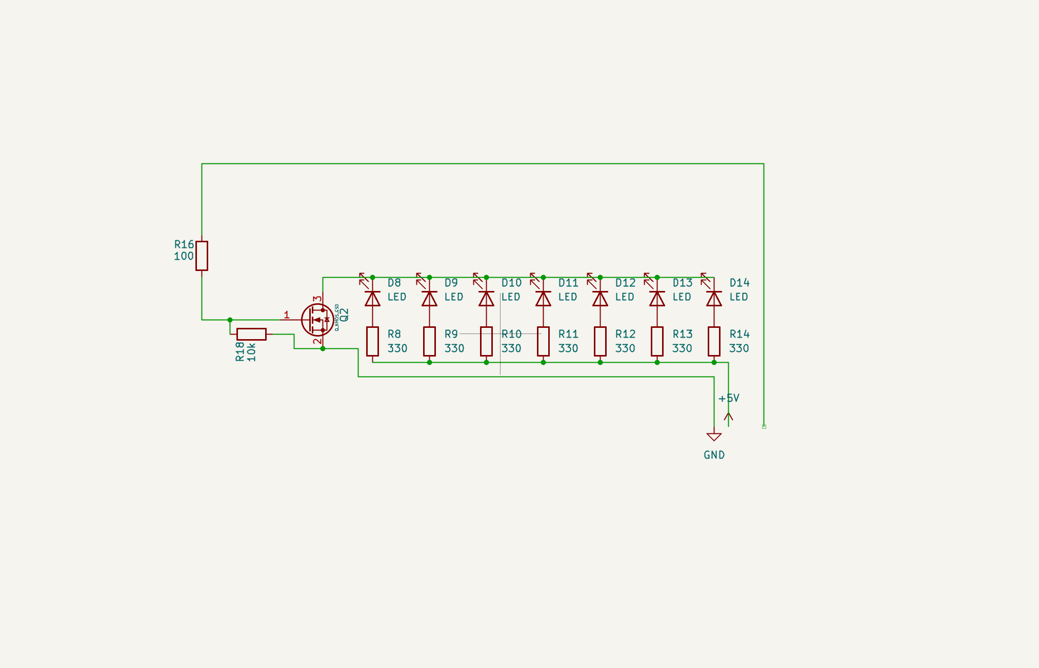
KiCad schematic — 7 LEDs in parallel, MOSFET switching with pull-down resistor
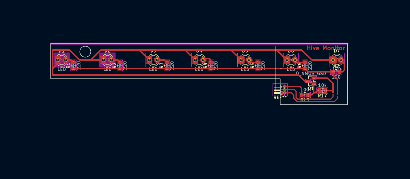
KiCad PCB layout — 7 LEDs in parallel with MOSFET switching
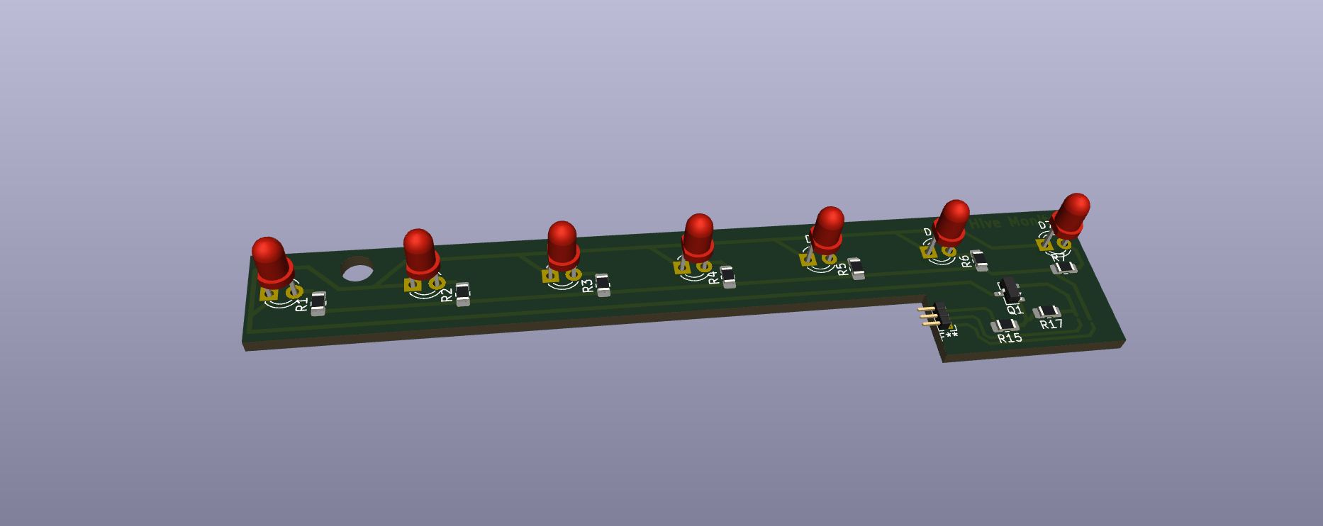
KiCad 3D viewer — LED board with components placed
Download the fabrication files:
Milling the Boards — Carvera CNC
Since I need 2 boards for each half of the hive (one white LED, one red LED — 4 boards total), I reformatted the layout to fit 3 boards side by side on a single panel. I generated the G-code in Carvera's software and milled it on the Carvera CNC. I ran the job twice, giving me 6 boards total — more than enough for the 4 I need, with spares in case of soldering mistakes.
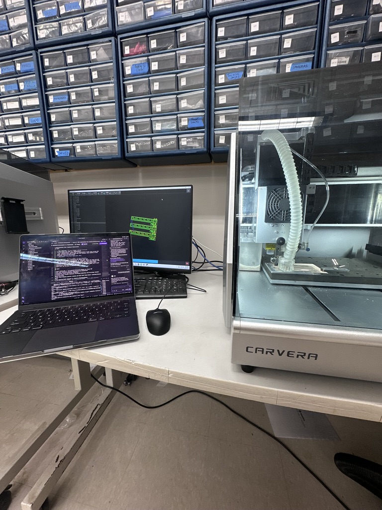
Milling the 3-up LED board panel on the Carvera CNC
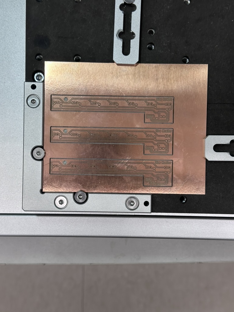
Successfully milled LED boards — 3 boards per panel, milled twice for 6 total
Download the G-code file for the 3-up board layout:
Testing the Board — LED On
After soldering the components, I tested the board by connecting 3.3V power, ground, and driving the MOSFET gate with a GPIO pin from the Raspberry Pi. When the GPIO goes HIGH, the MOSFET switches on and all 7 LEDs light up.
Microcontroller Board — XIAO ESP32-C6 (Week 8)
In the final project, the LED boards will be controlled by the XIAO ESP32-C6 development board that I milled in Week 8 — Electronics Production. The ESP32-C6 is the custom microcontroller board I designed and fabricated — it drives the MOSFET gate on the LED PCB HIGH or LOW via GPIO to switch the LEDs on and off. The ESP32-C6 handles the logic (day vs night, camera activation) and communicates with the Raspberry Pi 5 over the network.
The sensor extension board I designed in Week 9 will also be used in the LED system — extending the cable reach from the ESP32-C6 to the LED boards placed at different positions in the hive entrance housing, using the same STEMMA QT connector system.
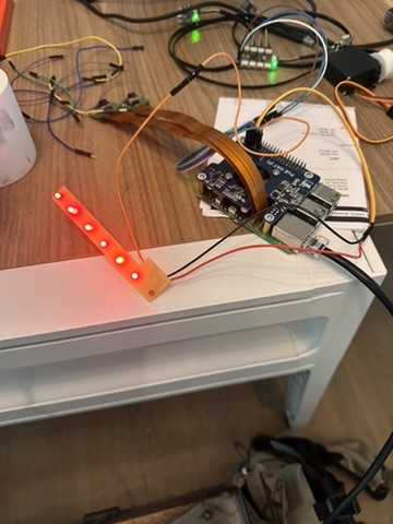
LED board working — all 7 LEDs lit up, powered from 3.3V with GPIO control
One of the 7 LEDs didn't light up during testing. I checked the solder joints and they were fine — it was just a bad LED. Since the LEDs are wired in parallel, the other 6 still work perfectly and provide plenty of light for the camera. I'll swap the dead one out when I do the final assembly.
Issue — "White" LEDs Are Actually Green
After testing, I discovered that the clear LEDs labeled "white" in the lab drawer are actually green LEDs, not white. I made the mistake of assuming they were white without testing the color first. This means the white LED boards I made won't work as intended for daytime viewing — green light isn't ideal for camera illumination. I won't be using these boards in the final project. The red LED boards work correctly and will still be used for nighttime viewing. Lesson learned: always test LED color before soldering an entire board.
Control Code — Python on Raspberry Pi 5
The LED boards are controlled from the Pi using the gpiod library (the modern replacement for RPi.GPIO on Pi 5). A single GPIO pin drives the MOSFET gate — HIGH turns the LEDs on, LOW turns them off.
# led_control.py
# Controls the custom LED PCB via MOSFET gate on GPIO 17
# Board wiring: 3.3V → LEDs → MOSFET drain, GPIO 17 → gate, GND → source

import gpiod
import time

# GPIO 17 controls the MOSFET gate for the LED board
LED_PIN = 17

# Open the GPIO chip (Pi 5 uses gpiochip4)
chip = gpiod.Chip('gpiochip4')
led_line = chip.get_line(LED_PIN)
led_line.request(consumer="led-board", type=gpiod.LINE_REQ_DIR_OUT)

try:
    # Turn LEDs ON
    led_line.set_value(1)
    print("LEDs ON")
    time.sleep(5)

    # Turn LEDs OFF
    led_line.set_value(0)
    print("LEDs OFF")

finally:
    led_line.release()
    chip.close()
How the Code Works
- GPIO 17: Connected to the MOSFET gate on the LED board. When driven HIGH (3.3V), the MOSFET conducts and completes the circuit from VCC through the LEDs to ground.
- gpiod library: The Pi 5 uses a new GPIO chip (
gpiochip4) and the legacy RPi.GPIO library doesn't work.gpiodis the modern Linux GPIO interface. - set_value(1): Drives the pin HIGH → MOSFET gate goes to 3.3V → MOSFET turns on → LEDs light up.
- set_value(0): Drives the pin LOW → MOSFET gate goes to 0V → MOSFET turns off → LEDs go dark. The 10kΩ pull-down resistor ensures the gate stays LOW when not driven.
In the final system, this same logic runs inside the hive-monitor agent — the Pi checks whether it's day or night and activates the appropriate board (white or red) when the cameras turn on.