For the individual assignment, I designed and fabricated a custom sensor extension PCB that allows me to extend the reach of my SHT45 temperature/humidity sensors throughout the beehive. The board interfaces with the Adafruit PCA9548 I²C multiplexer, which connects to the Raspberry Pi 5.
Sensor — Adafruit SHT45 with PTFE Membrane
For the input device, I'm using the Adafruit Sensirion SHT45 precision temperature and humidity sensor with a PTFE filter membrane. I have 3 of these sensors for the Smart Beehive project — one per hive box. The PTFE membrane makes them suitable for high-humidity environments like the inside of a beehive — it protects the sensor element from water and contaminants while still allowing accurate readings.
SHT45 Specifications
- Interface: I²C (address 0x44)
- Temperature accuracy: ±0.1°C
- Humidity accuracy: ±1% RH
- PTFE membrane: Protects against water, dust, and contaminants
- Voltage: 3.3V
- Quantity: 3 (one per hive box)
Sensor Extension Board — Longer Cable Runs
I have 3 SHT45 sensors that will be placed in each hive box to monitor temperature and humidity at different levels. The problem is the longest STEMMA QT / Qwiic cable I can get from Adafruit is only 300mm — not long enough to reach from the multiplexer at the bottom of the hive up through the boxes to where the sensors need to sit.
So I designed a simple extension board with two female connectors on either end. By chaining a 300mm cable into the extension board and then another 300mm cable out the other side, I can double (or triple) the reach. The board is just a pass-through — it connects VCC, GND, SDA, and SCL straight through from one connector to the other. Simple, but it solves the cable length problem without needing to solder custom-length cables.
The extension board uses the same STEMMA QT / Qwiic connector system from Adafruit — a standardized 4-pin JST SH connector that carries I²C (SDA, SCL, 3.3V, GND). This makes the whole sensor system modular and easy to work with: sensors, multiplexer, and extension boards all click together with the same cables. No soldering, no custom wiring — just plug and go.
Designing the Board
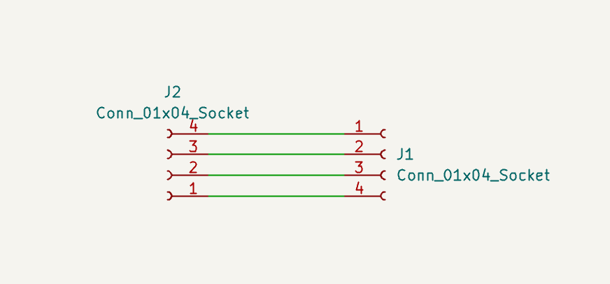
Schematic — simple pass-through connecting VCC, GND, SDA, and SCL between two STEMMA QT connectors
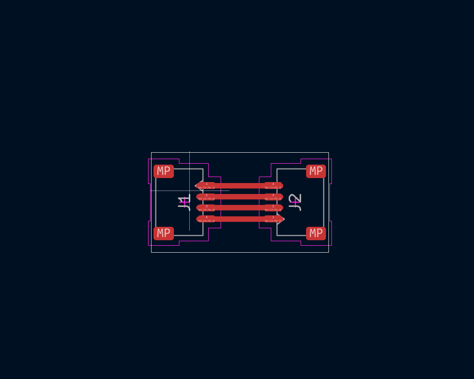
PCB layout — two connectors with traces routing the I²C signals straight through
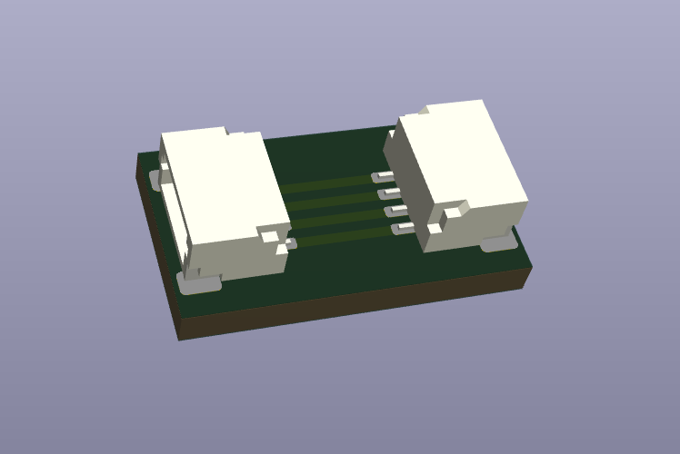
3D board preview — compact extension board with connectors on each end
Milling & Soldering the Extension Board
Milled sensor extension board — ready for soldering
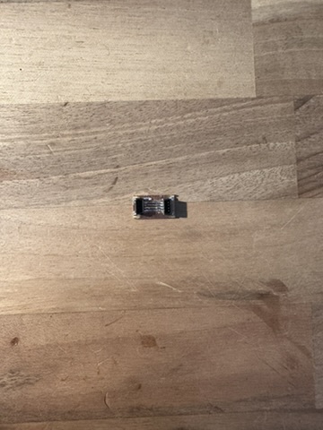
Soldered extension board with both STEMMA QT connectors attached
Connector Rotation Fix
After I plugged everything together for the first time, I discovered an issue — the STEMMA QT cables can only be plugged in one way (they're keyed), and both connectors on my board were facing the same direction. This meant the pin order was mirrored between the two connectors — SDA on one side was connecting to SCL on the other, and vice versa. The signal wasn't passing through correctly.
The fix was to rotate one of the connectors 180° on the board so that when a cable plugs into each side, the pins line up correctly: VCC→VCC, GND→GND, SDA→SDA, SCL→SCL. I made this change to the design, resoldered the connector, and tested again — this time it worked perfectly.
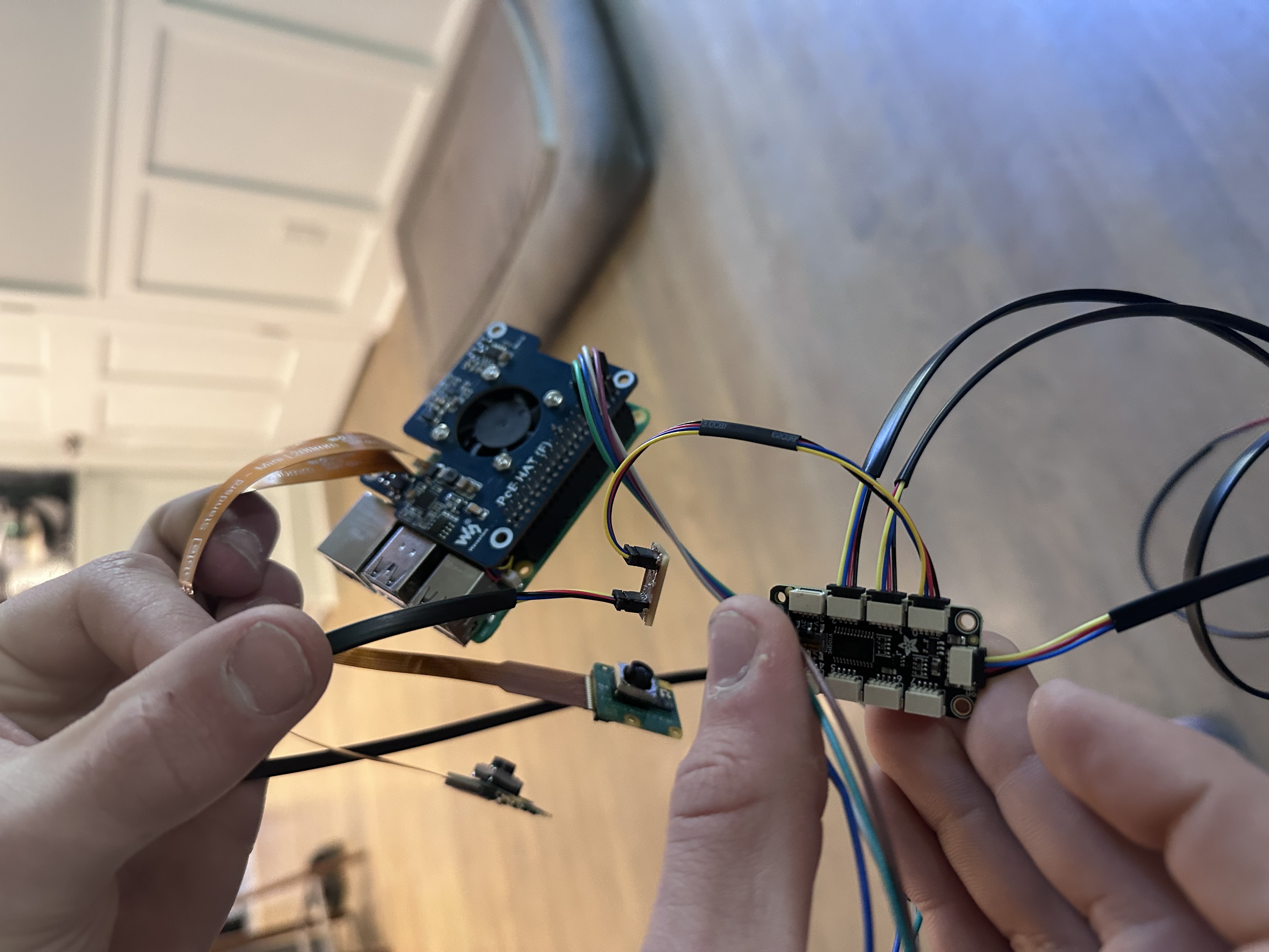
Extension board plugged into the sensor chain — connector rotation fixed
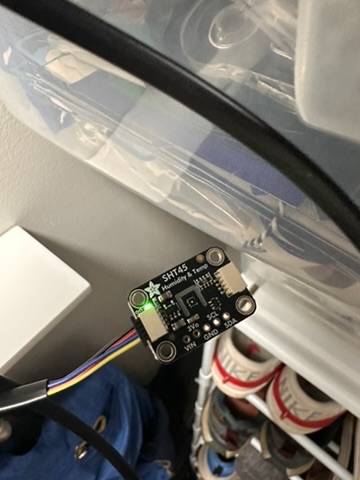
Successful test — sensor readings coming through the extension board after the connector rotation fix
Multiplexer Wiring — Adafruit PCA9548
Each SHT45 sensor is connected to the Adafruit PCA9548 I²C multiplexer, which allows the Pi to talk to all 3 sensors (they all share the same I²C address 0x44). The multiplexer sits at address 0x70 on the I²C bus and switches between channels to read each sensor individually.
| Pi GPIO | Mux Pin | Wire Color |
|---|---|---|
| 3V3 | VIN | Red |
| GND | GND | Black |
| GPIO 3 (SCL) | SCL | Yellow |
| GPIO 2 (SDA) | SDA | Blue |
Sensor channel assignments:
- Sensor 1 → Mux Channel 0
- Sensor 2 → Mux Channel 1
- Sensor 3 → Mux Channel 2
Each sensor connects to the multiplexer via STEMMA QT cables (and extension boards where needed for longer runs). The whole chain is: Pi → Multiplexer → STEMMA QT cable → Extension board (if needed) → STEMMA QT cable → SHT45 sensor. The modularity of the STEMMA QT system makes it easy to add, remove, or reposition sensors without any rewiring.
Reading the Sensor — Python on Raspberry Pi 5
Microcontroller Board — XIAO ESP32-C6 (Week 8)
The microcontroller board I designed and fabricated for this project is the XIAO ESP32-C6 development board that I milled in Week 8 — Electronics Production. I took the Gerber files, generated G-code using the Carvera software, milled the board on the Carvera CNC, soldered the components, and tested it with a blink program. This is the custom microcontroller board I made — it has GPIO pins and I²C support to interface directly with hardware.
In the full system, the Raspberry Pi 5 reads the SHT45 sensors via I²C through the PCA9548 multiplexer and my custom extension board. The full signal chain: Pi 5 → I²C → PCA9548 Multiplexer → STEMMA QT cable → Extension Board → STEMMA QT cable → SHT45 sensor. The Pi reads temperature and humidity data from each sensor through the multiplexer using Python and the Adafruit CircuitPython libraries.
The extension board I designed here will also be used in the LED lighting system — extending the cable reach from the XIAO ESP32-C6 board (milled in Week 8) to the custom LED PCBs placed at different positions in the hive entrance housing, using the same STEMMA QT connector system.
Libraries Used
adafruit-circuitpython-sht4x— driver for the SHT45 sensoradafruit-circuitpython-tca9548a— driver for the PCA9548 I²C multiplexeradafruit-circuitpython-busdevice— I²C bus abstraction
Installation
pip3 install adafruit-circuitpython-sht4x adafruit-circuitpython-tca9548aCode — Reading 3 SHT45 Sensors via Multiplexer
# read_sensors.py
# Reads temperature and humidity from 3x SHT45 sensors
# connected via PCA9548 I2C multiplexer on Raspberry Pi 5

import time
import board
import adafruit_sht4x
import adafruit_tca9548a

# Initialize I2C bus and multiplexer
i2c = board.I2C()
mux = adafruit_tca9548a.TCA9548A(i2c)

# Sensor locations in the hive
sensor_labels = ["Bottom Box", "Middle Box", "Top Box"]

while True:
    print(f"--- Hive Sensor Readings ---")
    for channel in range(3):
        try:
            sensor = adafruit_sht4x.SHT4x(mux[channel])
            sensor.mode = adafruit_sht4x.Mode.NOHEAT_HIGHPRECISION
            temperature = sensor.temperature
            humidity = sensor.relative_humidity
            print(f"  {sensor_labels[channel]}: {temperature:.1f}°C  |  {humidity:.1f}% RH")
        except Exception as e:
            print(f"  {sensor_labels[channel]}: Error - {e}")
    print()
    time.sleep(5)
Example Output
--- Hive Sensor Readings ---
  Bottom Box: 33.2°C  |  58.4% RH
  Middle Box: 34.7°C  |  62.1% RH
  Top Box: 35.1°C  |  65.8% RH
Relating Measurements to Physical Properties
The SHT45 measures two physical properties:
- Temperature (°C) — The sensor contains a tiny heating element and thermistor. It measures the thermal energy of the air passing through the PTFE membrane. Inside a healthy beehive, the brood nest is maintained at approximately 34–36°C by the bees. Readings outside this range can indicate problems — too cold means the colony is struggling, too hot could mean overheating or direct sun exposure.
- Relative Humidity (% RH) — The sensor has a capacitive humidity element that changes capacitance as water vapor is absorbed. Bees maintain hive humidity around 50–70% RH. High humidity (>80%) can promote mold growth and disease, while low humidity can dry out developing brood. The PTFE membrane is critical here — it prevents liquid water and contaminants from reaching the sensor while still allowing water vapor through for accurate readings.
By placing sensors at three levels in the hive (bottom, middle, top), I can monitor the temperature and humidity gradient. Heat rises, so the top box is typically warmest. This data helps assess colony health without opening the hive and disturbing the bees.
Custom Board — XIAO ESP32-C6 Connected to Sensors
What I Learned
Interfacing the SHT45 sensors through the I²C multiplexer taught me how I²C addressing works at a practical level — all three sensors share the same address (0x44), so the multiplexer switches between channels to talk to each one individually. I also learned that cable length matters for I²C reliability, which is why I designed the extension board to maintain signal integrity over longer runs.
The physical property relationship: the SHT45's capacitive humidity element changes capacitance as water vapor is absorbed, and the thermistor changes resistance with temperature. The sensor's onboard ADC converts these analog changes to digital readings (°C and %RH) over I²C — so the measured digital values directly correspond to real physical temperature and humidity inside the hive.
Board Design & Fabrication
The microcontroller board used in this system is the XIAO ESP32-C6 development board that I milled during Week 8 — Electronics Production. I took the provided Gerber files, generated G-code using the Carvera MakerCAM software, milled the board on our Carvera desktop CNC, soldered the components, and tested it with a blink program. Full design and fabrication documentation is on the Electronics Production page.
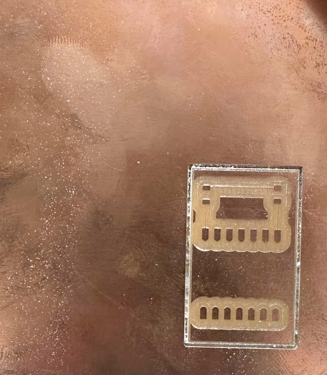
CNC milled ESP32-C6 board (hero shot)
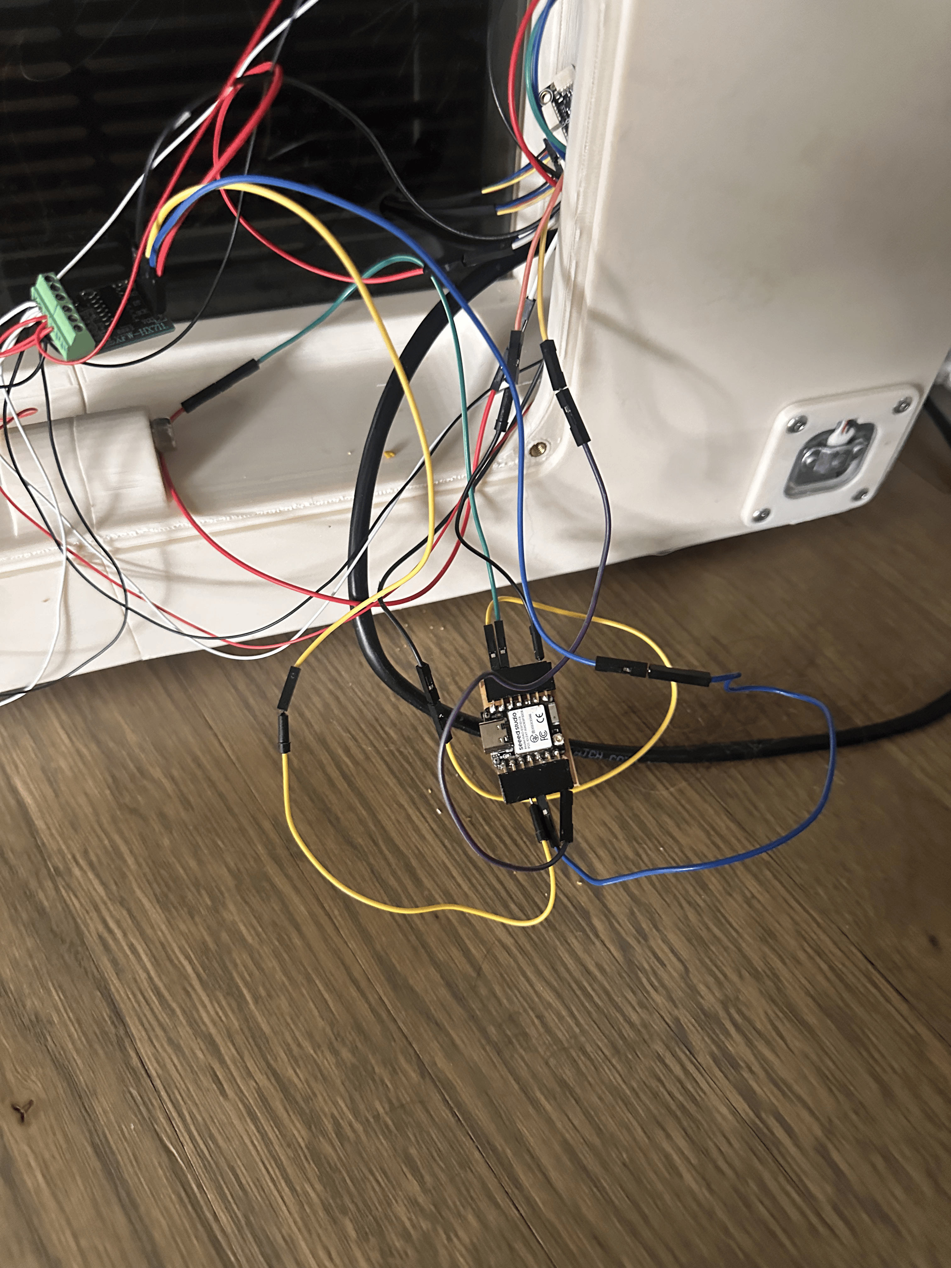
Custom board plugged into the system
How the Code Works
The ESP32-C6 runs Arduino firmware that reads the HX711 load cell amplifier every second, averages 55 samples over 60 seconds, then sends a JSON telemetry payload to the Raspberry Pi 5 via hardware UART (Serial1 on pins D6/D7 at 115200 baud). The Pi then publishes this data alongside the SHT45 sensor readings to AWS IoT Core via MQTT.
The SHT45 sensors are read by the Pi directly (Python + adafruit_sht4x library) through the PCA9548 multiplexer and my extension board. The ESP32-C6 handles the weight measurement independently and feeds it into the same data pipeline.
Problems Encountered & Fixes
- Extension board connector mirrored: The STEMMA QT connectors were facing the same direction, so SDA/SCL were swapped between the two sides. Fixed by rotating one connector 180° and resoldering — then it worked perfectly.
- Custom board wiring: The milled PCB pads are smaller than a standard dev board, making it harder to plug in jumper wires. Solved by being more careful with the connections and using shorter wire runs.
Original Design Files & Source Code
Board design files (Gerber, G-code, MakerCAM project) are available on the Electronics Production page. The sensor reading code is shown above in the "Reading the Sensor" section.
Design Files
Sensor Extension Board: