Visual documentation of the Smart Beehive intelligent monitoring system
Smart Beehive System
An integrated beekeeping monitoring system combining an entrance camera, environmental sensors, and smartphone connectivity for real-time hive management.
Entrance Camera
Camera mounted at the hive entrance to monitor bee activity, powered by a Raspberry Pi 5.
Environmental Sensors
Temperature and humidity monitoring for accurate hive health assessment.
Real-Time Data Logging
Connects to your smartphone or other device to track and log live hive data with historical trends and alerts.
Project Presentation
Summary Slide
FAB ACADEMY 2026 · FINAL PROJECT · CHARLOTTE FAB LABOLIVER ABBOTT
Bee Monitor
Intelligent Hive Monitoring System
Raspberry Pi 5-powered Langstroth hive monitoring with live cameras, environmental sensors, servo gate, and cloud dashboard — via single PoE cable.
Oliver Abbott Charlotte Fab Lab · Fab Academy 2026
INSTALLED & WORKING
Sensor Chain
LED PCB
CNC Milling
Cedar Roof
3
SHT45 Sensors
2
Entrance Cameras
5
Custom PCBs Made
1
PoE Cable
Stack
CNC Cedar RoofDone
Sensor PCBDone
LED PCBs ×4Done
Cloud DashboardDone
3D HousingPrinting
AssemblyIn Progress
Fab Academy 2026 Charlotte Latin Fab Lab
Project Video
Bee Monitor — Final Project Video (≤1 min, 1080p)
Project Vision
The Smart Beehive combines an entrance camera, environmental sensors, and smartphone connectivity into one integrated monitoring system, all powered by a Raspberry Pi 5. It makes beekeeping accessible for beginners while providing powerful tools for large-scale operations.
What Worked & What Didn't
✅ Worked: All 3 SHT45 sensors reading reliably via I²C multiplexer through extension board
✅ Worked: Dual cameras streaming, PoE powering everything from one cable
✅ Worked: MQTT to AWS IoT Core stable, dashboard live at hive-monitor.com
✅ Worked: ESP32-C6 reading HX711 weight sensors over UART to Pi
✅ Worked: CNC cedar roof fits perfectly after V2 redesign
✅ Worked: 3D printed housings (ASA + PLA) fit together with heat set inserts
❌ Didn't work: "White" LEDs turned out to be green — won't use for daytime lighting
✅ Fixed: Extension board connector orientation was mirrored on first attempt — rotated 180° and resoldered, then worked perfectly
❌ Didn't work: Inner cover dovetail key joints too weak — need better tolerances
How Was It Evaluated
Success criteria: all sensors reporting to cloud dashboard, cameras streaming, system running unattended on PoE. The system currently runs autonomously — Pi boots, connects to AWS, and starts reporting sensor data and serving camera feeds without any manual intervention.
Implications
This project demonstrates that a full IoT monitoring system can be built with digital fabrication tools — custom PCBs, CNC woodworking, 3D printing, and embedded programming all come together into a functional product. The main implication is cost: at ~$500 per unit using off-the-shelf components, it's too expensive for most hobbyist beekeepers. But the architecture proves the concept, and cost reduction via custom PCB (replacing Pi + HAT + multiplexer with one board) could bring it to a viable consumer price point.
Target Users
Beginner Beekeepers: Simplified hive management with guided suggestions and alerts
Commercial Operations: Scalable monitoring for managing dozens or hundreds of hives
Research Institutions: Detailed data collection for studying bee behavior and colony health
Entrance Camera
Camera system mounted at the hive entrance to monitor bee activity
Sensor Data
Temperature and humidity monitoring for hive health
Actionable Insights
Sensor data and camera feeds help beekeepers make informed decisions
Midterm Review — Project Status & Planning
This section documents the current project status, system architecture, remaining tasks, and schedule for completion by June 12, 2026.
System Diagram
┌─────────────────────────────────────────────────────────────────┐
│                      SMART BEEHIVE SYSTEM                        │
└─────────────────────────────────────────────────────────────────┘

                    ┌──────────────────┐
                    │   House (500ft)  │
                    │                  │
                    │  PoE Switch /    │
                    │  PoE Injector    │
                    └────────┬─────────┘
                             │
                             │ Ethernet Cable
                             │ (Power + Data)
                             │ (500 feet)
                             │
                    ┌────────▼─────────┐
                    │   At The Hive    │
                    └──────────────────┘
                             │
                             │
                             │
    ┌────────────────────────▼───────────────────────┐
    │         RASPBERRY PI 5 (8GB RAM)                │
    │         Main Controller & Data Hub              │
    │         Powered via PoE HAT                     │
    │                                                 │
    │  • Reads sensors via I2C                       │
    │  • Captures video on-demand                    │
    │  • Uploads data to cloud dashboard             │
    │  • Power + network via single Ethernet cable   │
    └────┬────────────────────────────────────┬──────┘
         │                                    │
         │ I2C Bus                           │ CSI
         │                                    │
    ┌────▼────────────────┐         ┌────────▼─────────┐
    │  3× SHT45 Sensors   │         │  Pi Camera       │
    │  (Temp & Humidity)  │         │  Module 3        │
    │                     │         │  (12MP 120°)     │
    │  • Inside hive      │         │                  │
    │  • Outside hive     │         │  • Entrance view │
    │  • Brood chamber    │         │  • On-demand     │
    └─────────────────────┘         └──────────────────┘

    ┌─────────────────────────────────────────────────────┐
    │  XIAO ESP32-C6 (custom milled board)                │
    │  Connected to Pi via UART (D6 TX → Pi GPIO12 RX)   │
    │                                                     │
    │  • Reads HX711 ADC (weight measurement)            │
    │  • 4× 50kg load cells                              │
    │  • Sends JSON telemetry every 60s                  │
    └─────────────────────────────────────────────────────┘

    ┌──────────────────────────────────────────────────┐
    │           PHYSICAL STRUCTURE                     │
    │                                                  │
    │  • CNC Cedar Roof (V2 - completed)              │
    │  • 3D Printed Camera Housing                    │
    │  • Standard Langstroth Hive Boxes               │
    │  • Inner Cover (box joints - in progress)       │
    └──────────────────────────────────────────────────┘

                         │
                         │ Ethernet (via PoE)
                         │
                ┌────────▼─────────┐
                │   Cloud Server   │
                │   (Firebase/AWS) │
                │                  │
                │  • User Auth     │
                │  • Data Storage  │
                │  • API Endpoints │
                └────────┬─────────┘
                         │
                         │ HTTPS
                         │
                ┌────────▼─────────┐
                │  Web Dashboard   │
                │                  │
                │  • Live Data     │
                │  • Video Access  │
                │  • Alerts        │
                │  • Multi-User    │
                └──────────────────┘
Bill of Materials (Purchased Items)
Component
Qty
Unit Price
Total
Status
Raspberry Pi 5 (8GB RAM)
1
$200.00
$200.00
✅ Purchased
Pi Camera Module 3 (12MP 120°)
2
$38.50
$77.00
✅ Purchased
SHT45 Temp/Humidity Sensors (PTFE)
3
$13.50
$40.50
✅ Purchased
Cedar boards (1×6×8')
6
$18.27
$109.62
✅ Purchased
Hope's 100% Pure Tung Oil
1
$29.99
$29.99
✅ Purchased
PoE Switch or PoE Injector
1
~$30.00
~$30.00
⏳ Planned
PoE HAT for Raspberry Pi 5
1
~$20.00
~$20.00
⏳ Planned
Outdoor Ethernet Cable (500ft)
1
~$50.00
~$50.00
⏳ Planned
Total (Purchased)
$457.11
Estimated Additional
~$240+
Project Total (Estimated)
~$750+
Task List — Remaining Work
✅ Completed Tasks
✅ Design and 3D print camera housing (Week 1-2)
✅ CNC cut cedar roof V2 with dowel joints (Week 7)
✅ Design and mill sensor extension PCB (Week 9)
✅ Integrate OLED display for sensor readouts (Week 10)
✅ Test SHT45 sensors with CircuitPython
✅ Document all weekly assignments (Weeks 1-10)
⏳ In Progress
⏳ Inner cover with box joints (Week 11-12)
⏳ PoE networking research and planning
❌ Not Started (Priority Order)
1. Purchase and install PoE hardware (PoE switch/injector, PoE HAT, Ethernet cable)
2. Wire SHT45 sensors to Pi 5 via I2C
3. Mount Pi Camera Module 3 in entrance housing
4. Develop Python sensor reading script
5. Set up cloud database (Firebase or AWS)
6. Build web dashboard with user authentication
7. Implement on-demand video streaming
8. Run Ethernet cable and set up PoE power delivery
9. Final hive assembly and weatherproofing
10. Field testing and calibration
11. Create final project video and slide
12. Complete final documentation
Project Schedule — Gantt Chart
Timeline: Week 7 → June 12, 2026 (Final Presentation)
PoE System: Must be purchased and tested early (Week 11-12) — Ethernet cable run to hive is critical for both power and data
Software Development: Dashboard and data pipeline are complex — allocate 3-4 weeks (Weeks 13-16)
Ethernet Cable Run: 500ft outdoor cable needs to be buried or protected from weather and animals
⚠️ Medium Risk
Video Streaming: Ethernet provides plenty of bandwidth, but compression may still be needed for cloud upload
Sensor Wiring: Clean routing through hive boxes without disturbing bees
Weather Sealing: Electronics must be protected from moisture
✅ Low Risk
Mechanical Assembly: Hive construction is well-documented and tested
Sensor Reading: SHT45 sensors already tested and working
Camera Integration: Pi Camera Module 3 is well-supported
Next Steps for Instructor Review
Ready for Discussion:
✅ System architecture and component selection
✅ Task breakdown and priority order
✅ 8-week schedule to June 12 deadline
✅ Risk assessment and mitigation strategies
I designed the entrance section of the beehive in Fusion 360. This is where the cameras will be mounted to monitor bee activity going in and out of the hive.
Initially I planned to use a single camera, but after researching cameras compatible with the Raspberry Pi 5 and looking at their focal lengths, I realized I'll need two cameras to get adequate coverage of the entrance. The plan is to run them off a Raspberry Pi 5.
V1 — First Design
The first version established the overall shape and dimensions of the entrance piece. I printed it in two sections so it would fit on the build plate.
Loading 3D model...
Smart Hive entrance V1 (half section) — designed in Fusion 360
V2 — Narrower Profile
After the first version, I decided to decrease the length of the part to make it narrower. This gives a tighter fit against the hive body and reduces wasted material.
Current Progress
I'm currently working on a version with an upper section to house the camera module. The goal is to have the camera securely mounted inside the entrance piece with a clear view of the landing board, all powered by a Raspberry Pi 5.
V10 — Final Design (3D Models)
The final design splits into two parts: the bottom board (electronics enclosure) and the entrance housing (camera and LED mount). Both were designed in Fusion 360.
Bottom Board
Holds the Raspberry Pi 5, Waveshare PoE HAT, I²C multiplexer, and all wiring. Mounts underneath the hive body with mounting posts, cable routing channels, and ventilation slots for the PoE HAT's cooling fan.
Bottom Board — holds the Pi 5, PoE HAT, and electronics. Click and drag to rotate, scroll to zoom.
Entrance Camera Housing
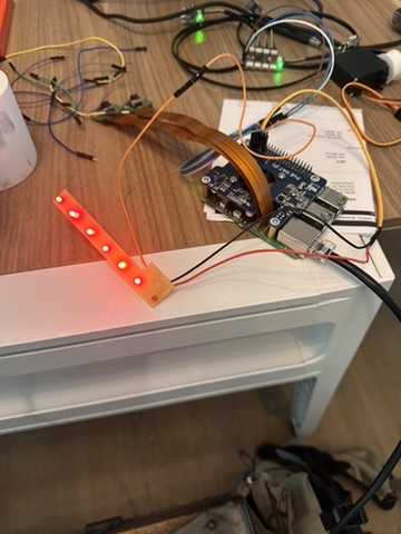
Mounts at the hive entrance holding both Pi Camera Module 3 Wide units and 4 custom LED PCBs (2 white, 2 red). Designed so cameras have a clear view of bees entering/exiting, with LEDs positioned outside the cameras' field of view. Integrates with the servo-driven rotating entrance gate.
The LED boards are controlled by the XIAO ESP32-C6 development board I milled in Week 8 — Electronics Production. The ESP32-C6 drives the MOSFET gate on each LED PCB via GPIO — HIGH turns the LEDs on, LOW turns them off. The sensor extension board designed in Week 9 is also used here to extend the cable reach from the ESP32-C6 to the LED boards at different positions in the housing, using the same STEMMA QT connector system.
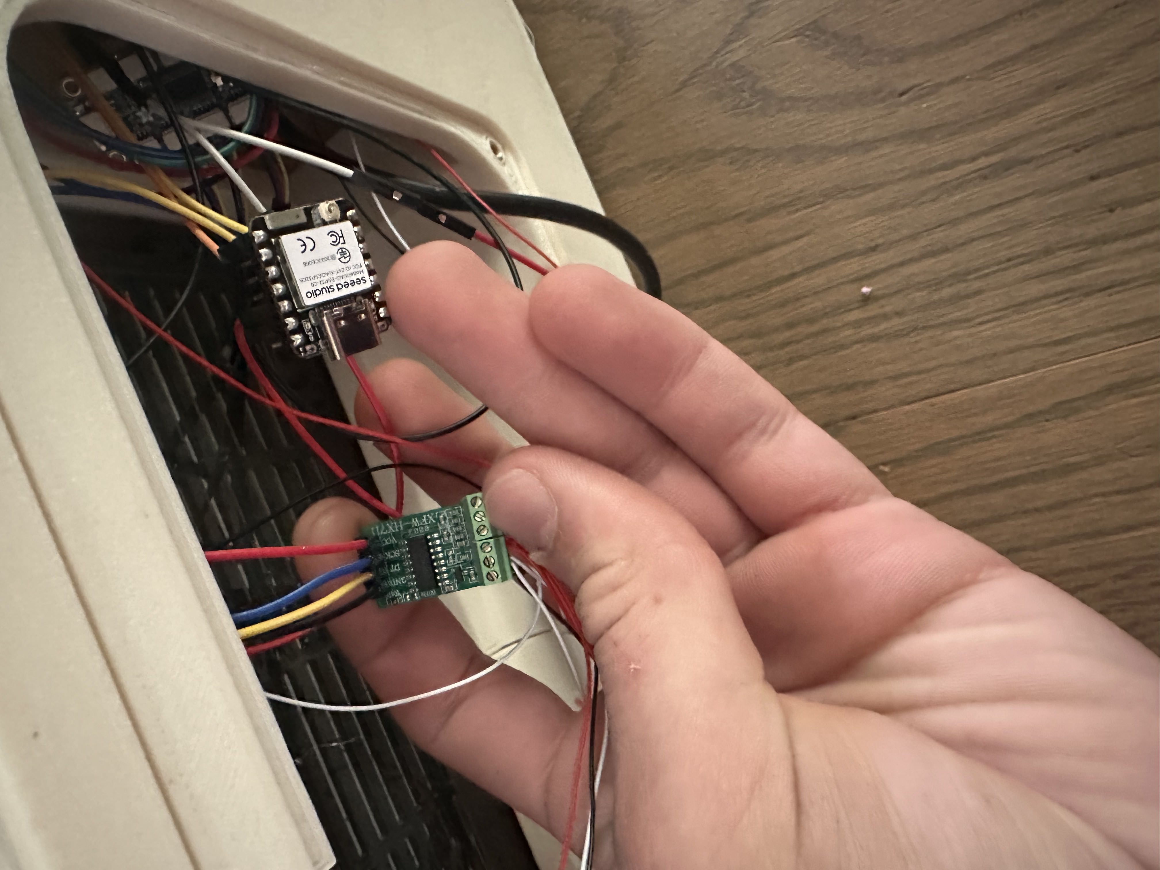
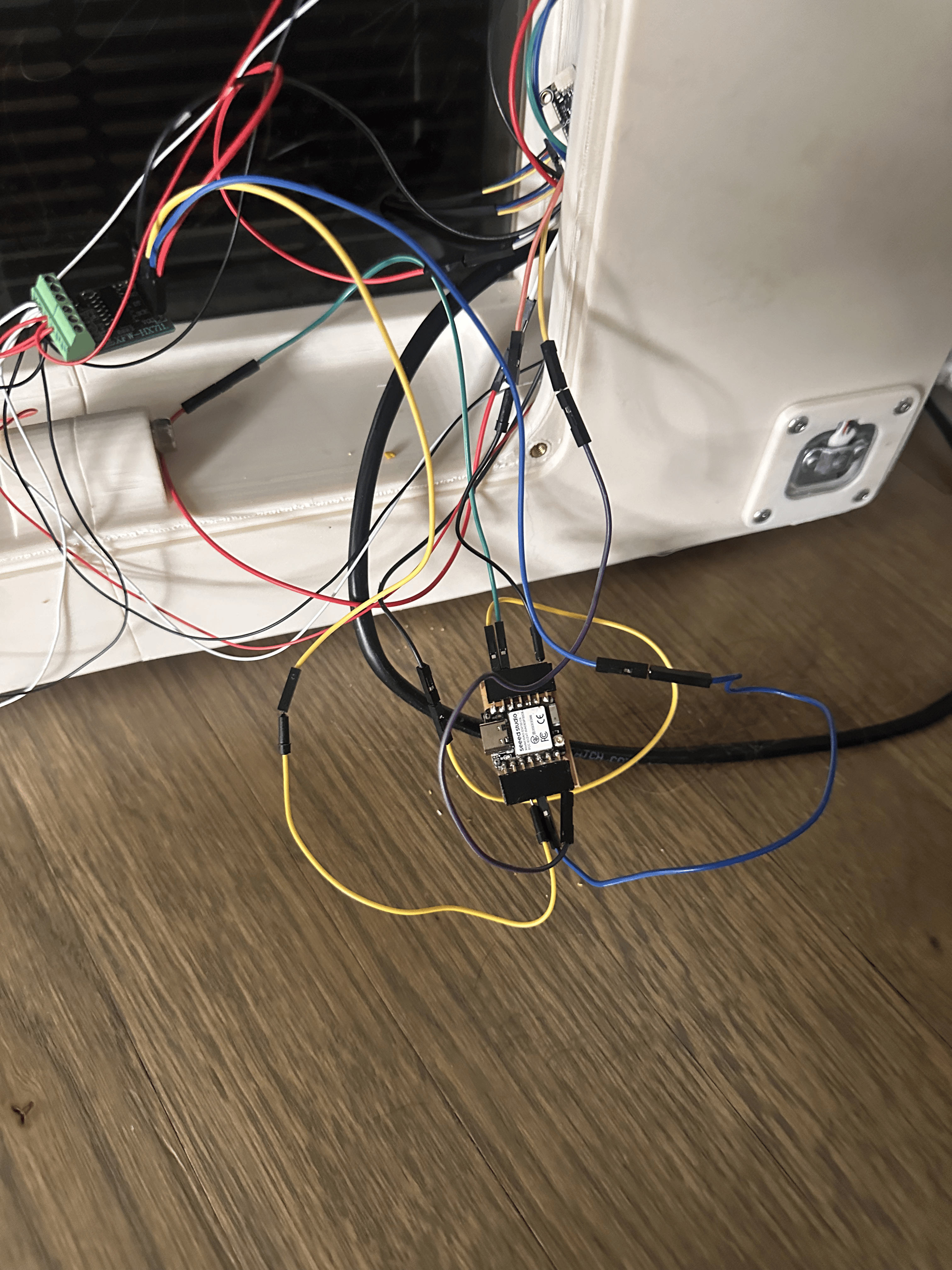
The XIAO ESP32-C6 reads the 4 load cells via the HX711 amplifier and sends weight data to the Pi 5 over UART. This photo shows it hooked up to a regular ESP32 development board during initial testing. Once I confirmed everything worked successfully, I swapped it out for the custom milled board from Week 8, which worked great as well — just a little harder to plug in the wires due to the smaller pad size on the milled PCB. It connects to the Pi via UART and reads the HX711 which is wired to all 4 load cells.
ESP32-C6 connected to HX711 + 4 load cells, wired to Pi via UART
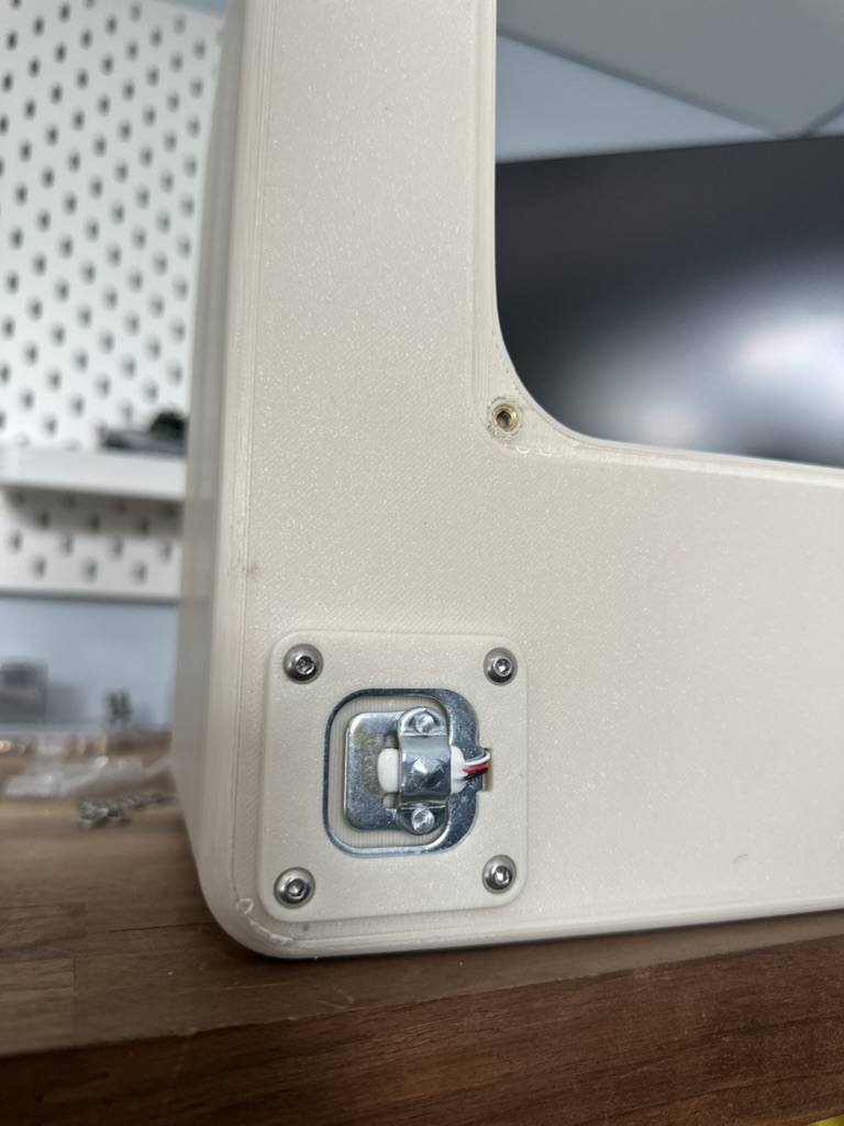
Load cells integrated into bottom board
Custom Milled Board — Electronics Production
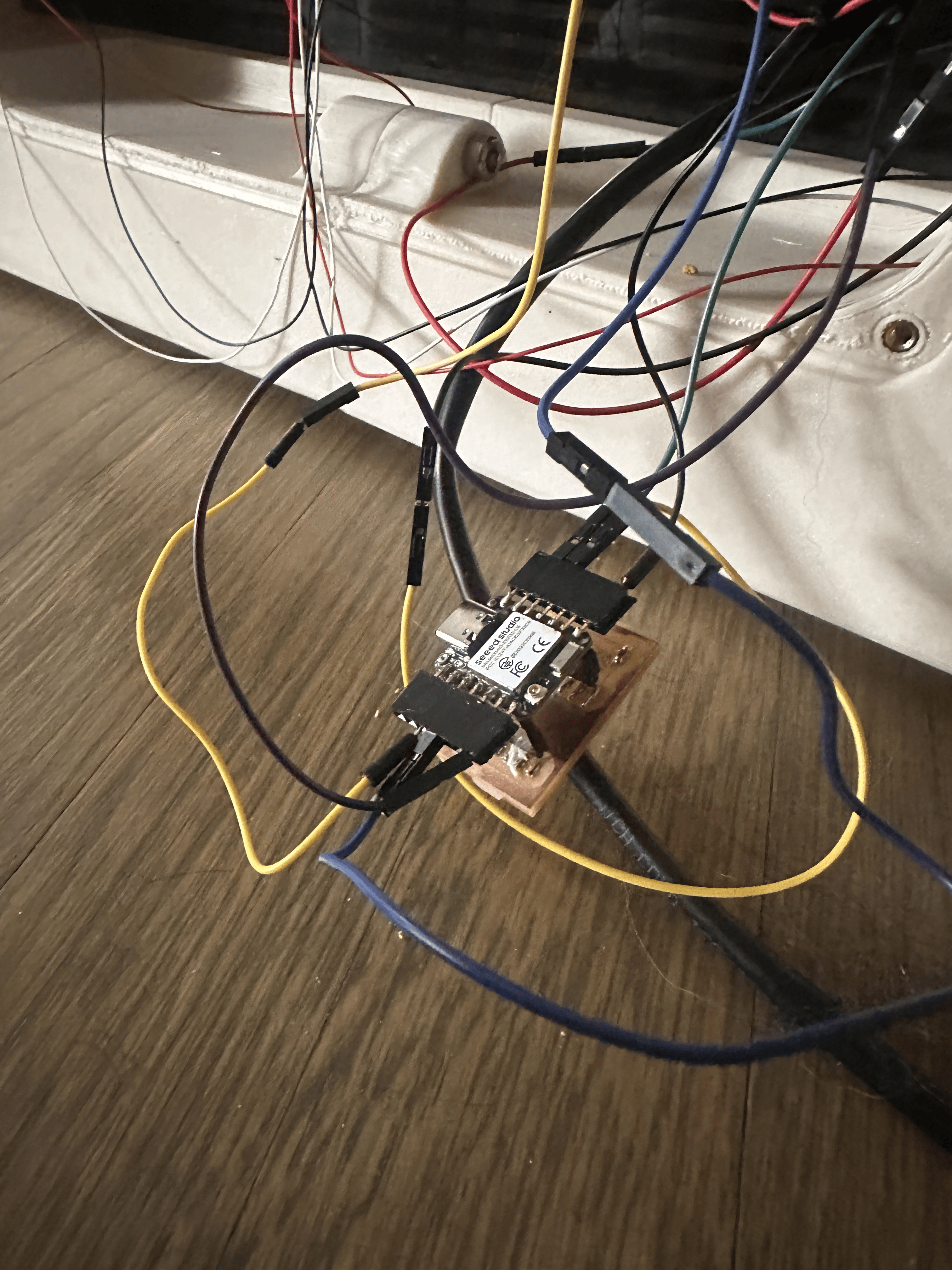
After confirming the system worked on the regular dev board, I swapped in the custom milled ESP32-C6 board from Week 8 — Electronics Production. It worked great — just a little harder to plug in the wires due to the smaller pads. Full documentation of the board design, milling, and soldering is on the Electronics Production week page.
Custom milled ESP32-C6 plugged into the system
Custom board wired to HX711 + load cells
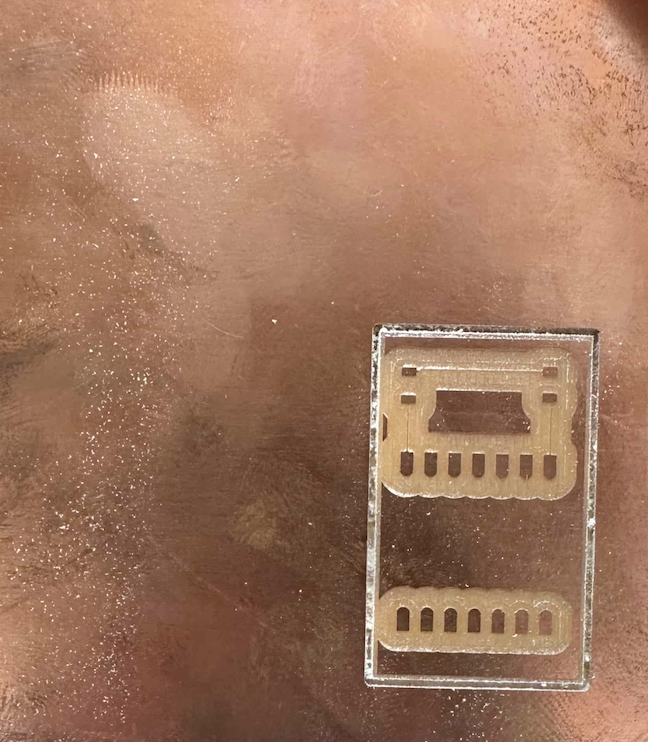
CNC milled board (Week 8)
LED blink test on the custom milled ESP32-C6 board — confirming it works
Entrance Camera Housing — holds both cameras and LED boards. Click and drag to rotate, scroll to zoom.
Camera Location — Entrance Housing Installed
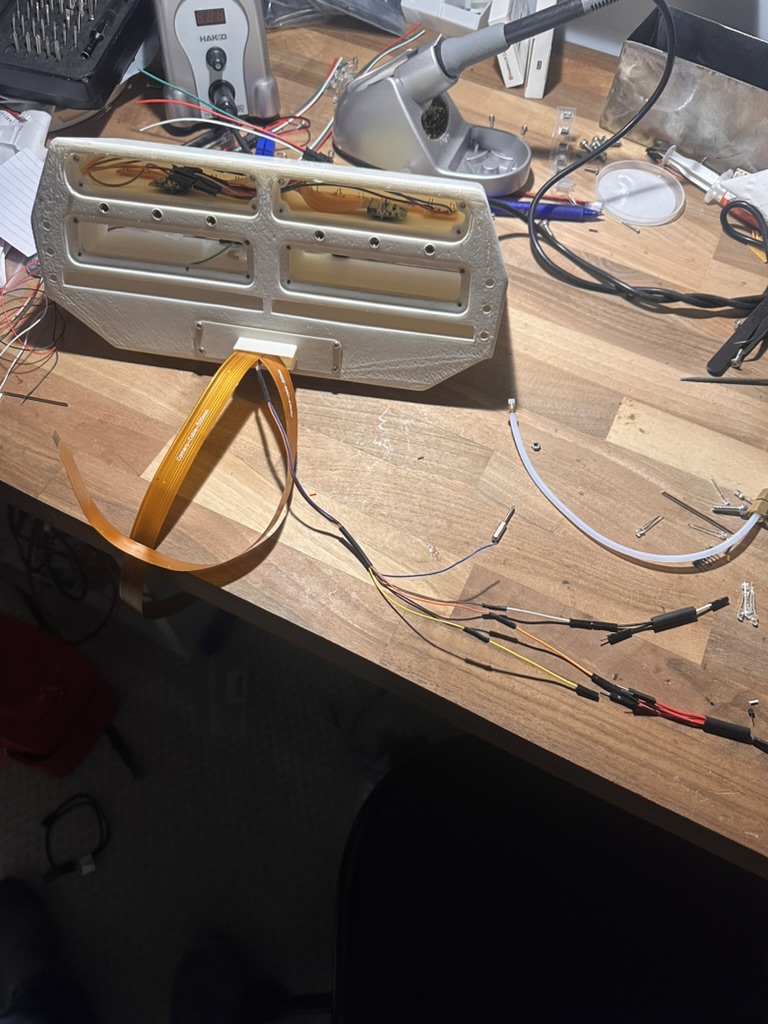
A camera is located on each side of the entrance — one per half of the hive entrance. This gives full coverage of bees entering and exiting. The cameras are mounted inside the 3D printed entrance housing along with the custom LED PCBs for illumination.
Entrance housing wired up — cameras on each side with LED PCBs installed
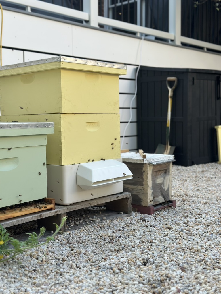
The Smart Beehive is built on a standard 10-frame Langstroth hive — the most common hive type in the United States. I chose cedar for the hive material because it's naturally rot-resistant, lightweight, and holds up well outdoors without needing chemical treatment. Cedar also has natural insulating properties, which helps the bees regulate temperature inside the hive through the seasons.
Hive Dimensions
Deep Hive Body: 9⅝" tall × 16¼" wide × 19⅞" long
Medium Super: 6⅝" tall × 16¼" wide × 19⅞" long
V1 — First Cut (Plywood Test)
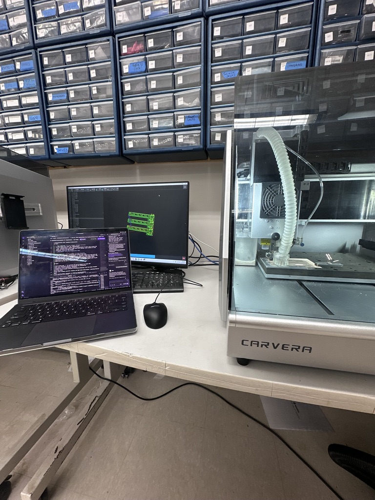
Our lab uses a ShopBot Alpha CNC router. For the first version of the roof I used plywood to test the design before committing to the nice cedar. The roof uses dowel joints — the holes on the sloped gable sections are cut on the CNC, with 3 dowels per corner at a ¼" hole size.
Cutting beehive roof V1 on the ShopBot Alpha CNC router
V1 Test Fit
I test fit the roof on an empty hive that I have ready for this upcoming season and noticed that it's about ¼" too long — you can see the gap by looking at the bottom edge in the photo below.
Roof V1 test fit — about ¼" too long, visible gap at the bottom edge
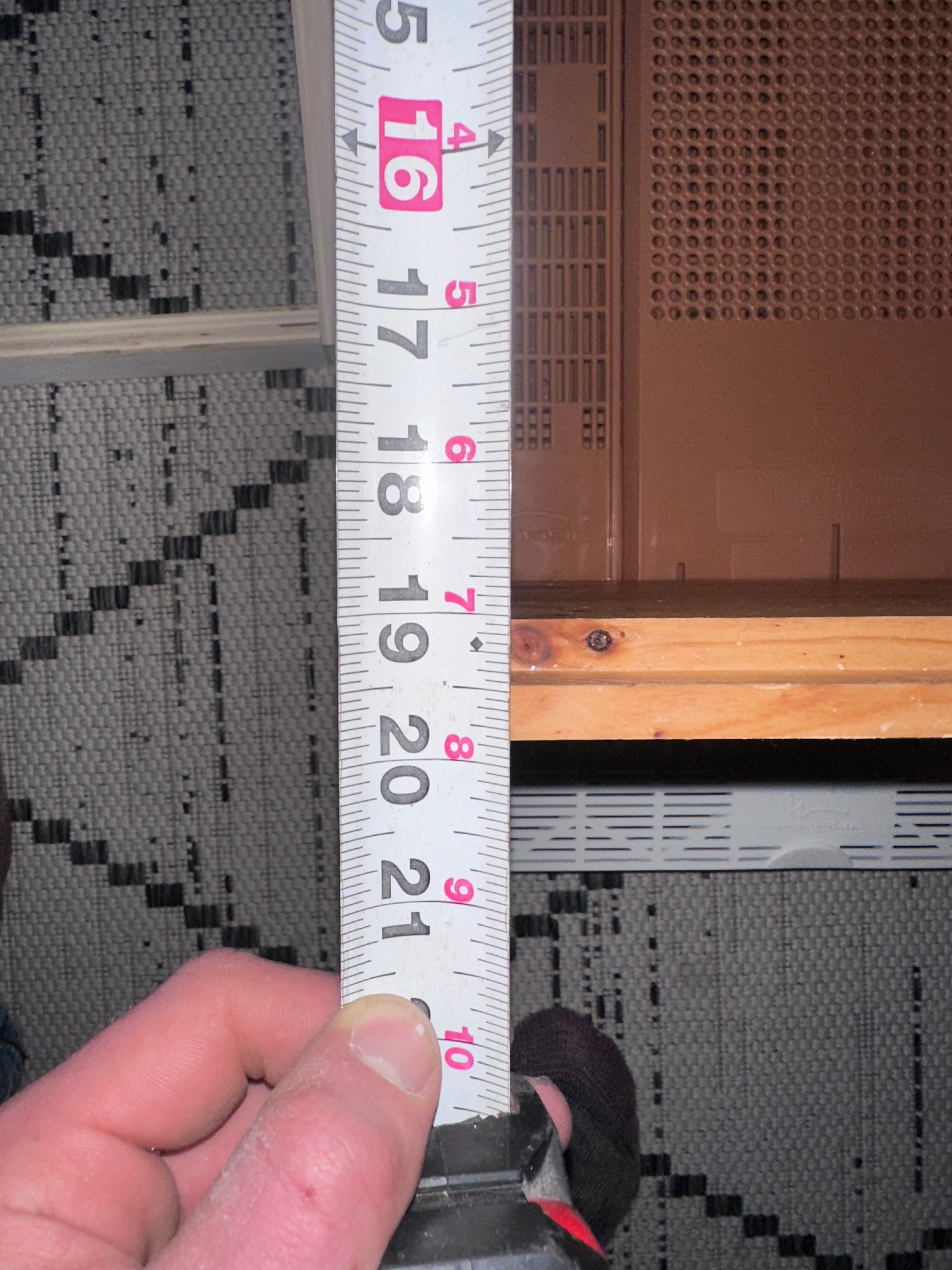
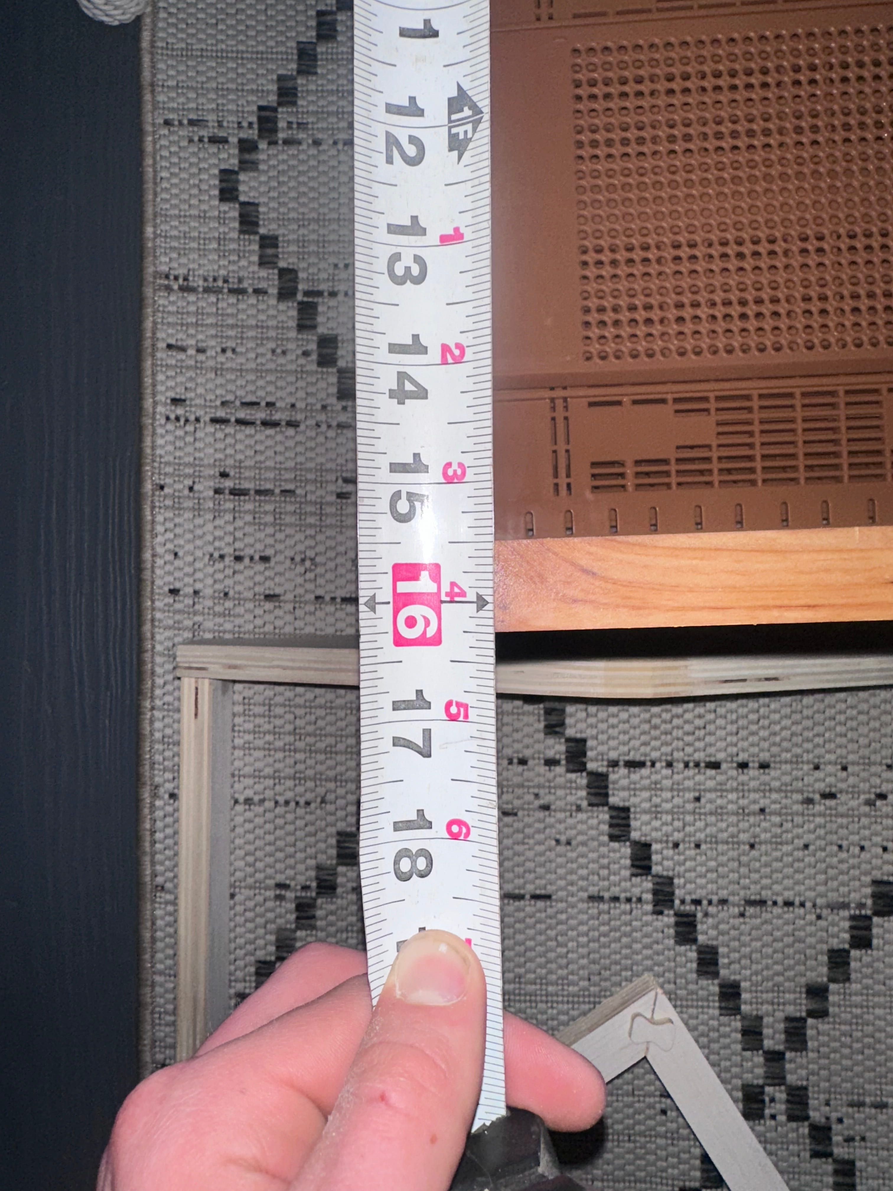
After noticing the overhang, I decided to take actual measurements of the hive box I'm fitting to.
Measuring the existing hive box — width
Measuring the existing hive box — length
Sourcing Cedar
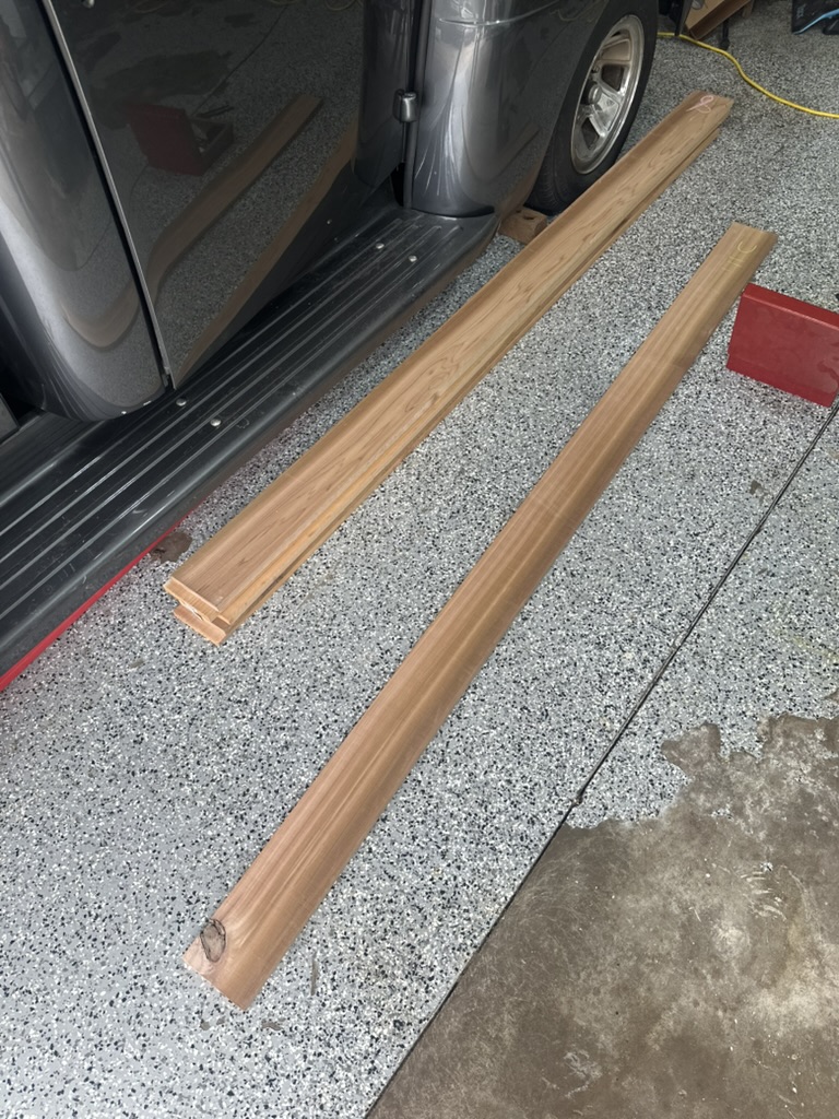
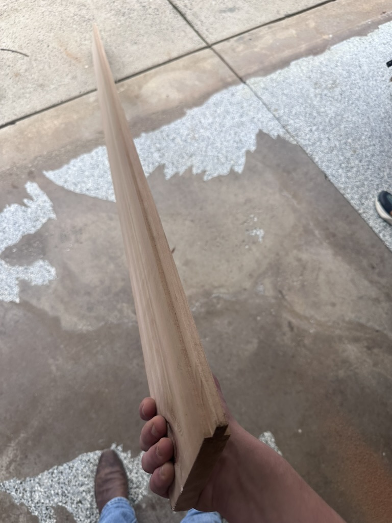
After testing with plywood, it was time to move to the real material. I bought 6 cedar boards from Lowe's at $18.27 each. Usually, select cedar boards with no knots are very expensive, so instead of paying the premium I decided to go in person and inspect each board individually, only buying the ones with very little to no knots. Knots are weak points in the wood — they can crack, fall out over time, or create gaps that let moisture and pests into the hive.
Hand-selected cedar boards with minimal knots
I measured the thickness at about 0.85", and I only need 0.75" for standard hive wall thickness. This is good because when I join the boards I'll need to plane them, so the extra material gives me room to work with.
Joining the Boards — Tongue & Groove
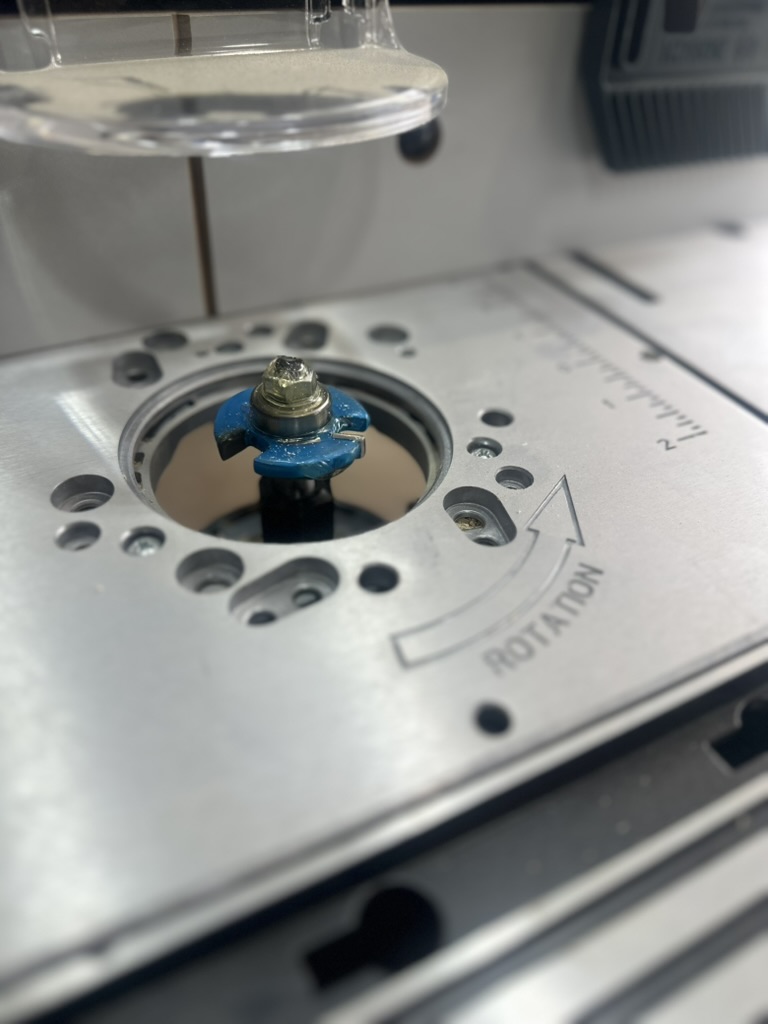
I needed a way to join these boards into wider panels and I didn't want to go out and buy a very expensive joiner tool. Instead, I bought a router bit from Rockler — specifically the 1-7/8" D × 1/4" H × 1/4" Shank Rockler 3 Wing Slotting Cutters Bit for $54.99. Much better than a $260 joining tool. I used this bit to make tongue and groove joints — cutting a centered tongue on one board edge and a matching groove on the adjacent board so they interlock.
Rockler 3 Wing Slotting Cutter bit attached to the router table
I attached the bit to my router table and cut the boards. It took lots of trial and error to get the fit right, but thankfully I didn't ruin any of the boards.
Tongue and groove joint cut into the cedar boards
Glue-Up & Planing
The next step was to glue the boards up. I used Titebond III wood glue, which is waterproof and rated for outdoor use — important for a beehive that sits outside year-round. I could only do one board at a time since I didn't have a lot of clamps.
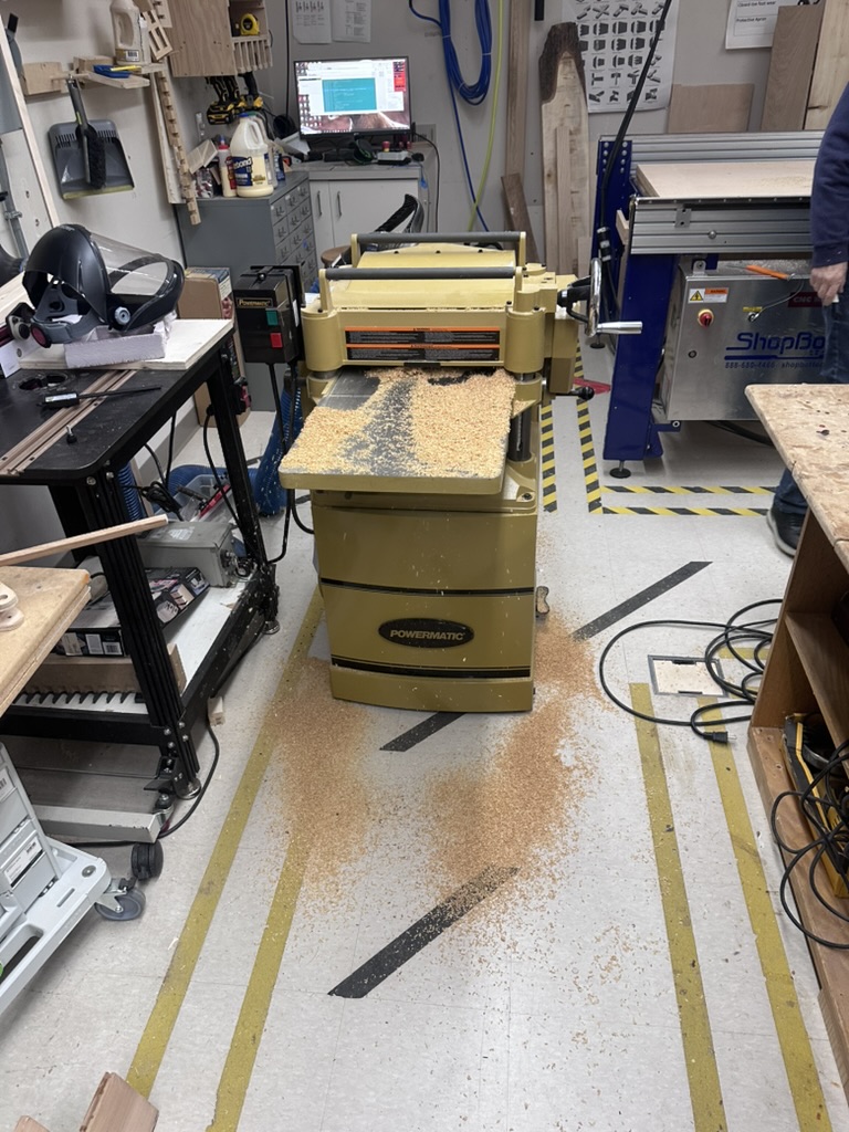
After they were all glued up, the boards had a small but noticeable bump where they were joined. I anticipated this — first I used a hand planer to remove the bulk of the material, also clearing off glue residue as I went. After getting it as good as I could by hand, the boards obviously weren't perfectly flat, so I brought them to the lab and used the thickness planer.
Running the joined cedar panels through the thickness planer at the lab
After a few passes and adjustments, running both sides of the boards through, I was able to get a very nice smooth flat surface.
V2 — Design Changes & Second Cut
Based on the V1 test fit, I made several design changes for V2:
Reduced the lengths of the rectangular side boards of the roof
Decreased the height of the gable sides, which lessens the slope
Made the ends not straight on purpose — this increases the amount the roof has to sit on, makes it easier to pick up, eliminates a 90-degree corner (which hides drilling error on the rectangular side boards), and I think it looks good
Cutting the V2 roof design on the ShopBot
After the roof was cut out I sanded each part and was very happy with the result, then took everything back home.
3D Printed Drill Jig & Side Board Problem
I 3D printed a jig to drill the dowel holes and align them up on the rectangular side boards. This is when I noticed the first problem — after getting the sides of the roof and a drill, I tried to place the jig on the wood and noticed that the side boards were cut too small. I think the CNC cut them on the inside of the vector instead of the outside.
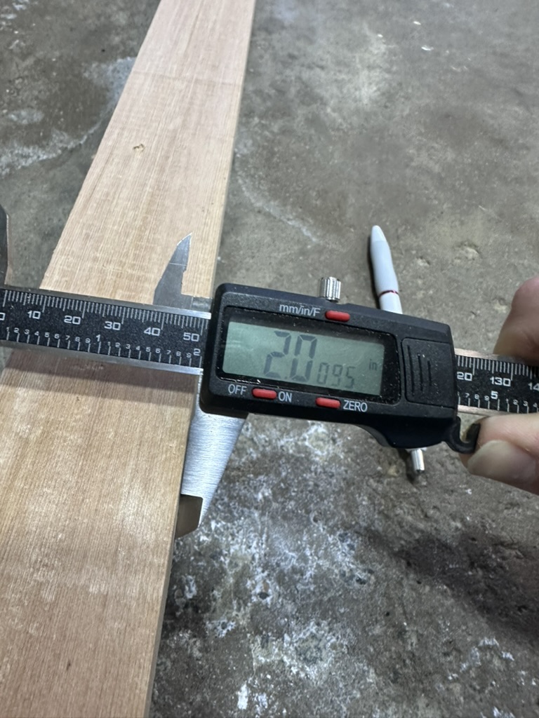
I was determined to get this done, and being on spring break meant I wouldn't be able to get back to the lab for over a week. So I decided to re-cut the side boards using my table saw at home.
Re-cut side board measuring 2.0095" — almost perfect
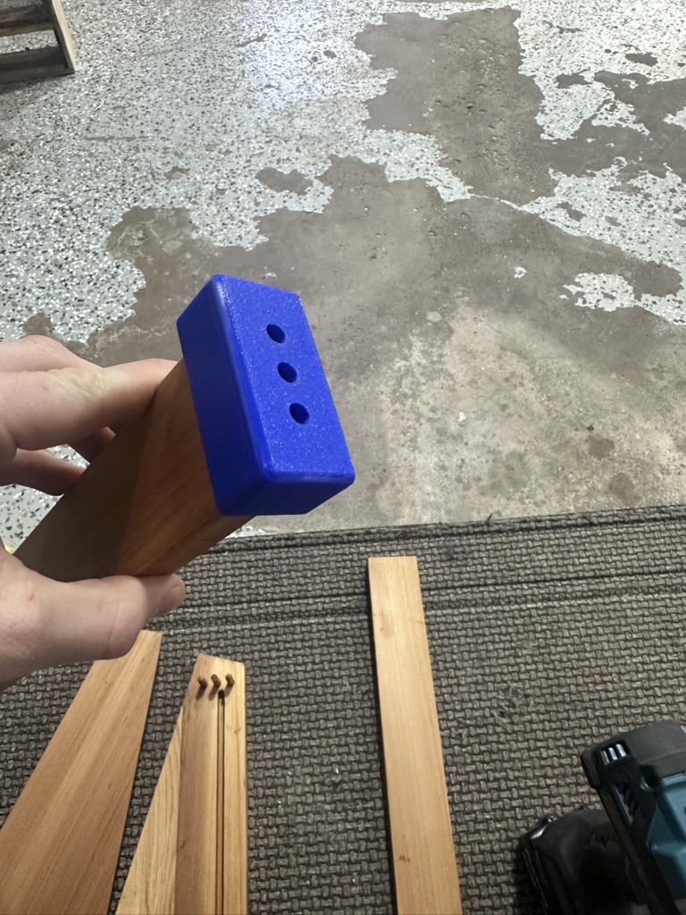
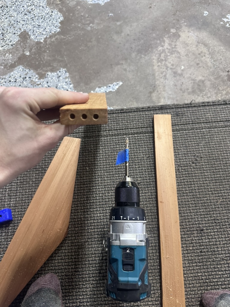
I slid on the 3D printed jig and it fitted perfectly. I pushed the dowels into the gable side of the roof (the holes were already drilled on the CNC), then measured the amount sticking out and put a piece of tape around my drill bit so I'd know the depth I needed to drill to.
3D printed jig clipped onto the side board for precise hole alignment
Tape on the drill bit as a depth reference
Finishing — Tung Oil
I finished all the parts using tung oil, which is what I use on my cedar bee hives that I don't paint. One important note: you have to use 100% pure tung oil and let it cure for around 30 days if you want to use it for bees. Most "tung oil" isn't really tung oil — anything labeled tung oil at your local hardware store is not likely even tung oil and is not food/bee safe (you need to read the label on the back of the package). I personally use Hope's 100% Pure Tung Oil ($29.99 on Amazon).
The best method I found for applying it:
Apply a generous amount to the wood
Leave it in the sun for 20 minutes
Wipe it down
Let it sit in the sun for around 2–3 hours
I repeated this process 3 times and was happy with the result. Note that you have to wait around 30 days for it to fully cure.
Roof Assembly
After applying the 3 coats of tung oil finish, I bought a piece of ¼" lauan plywood from Lowe's to sit in the groove I made in the gable side of the roof. I cut the ply to the correct dimensions on the table saw, slid it in, and glued up all of the sides.
Interior Supports: One thing I should have done was add a groove for the plywood board in the rectangular sides of the roof. Since I hadn't done that, I decided to improvise — I used the previously too-narrow pieces of wood and cut a 15-degree slope on them using the table saw, which was about as close as I could get to match the slope of the roof. I glued them on the inside face and then used the nail gun to put nails from the bottom of the board up into the support. Since these pieces were also not long enough, I used some wedges to get the fit right, then glued up the faces and clamped them together.
Top Support: I also realized I would need to make a top support — something to add strength and also have something to nail the roof board into. I made the top support from some scrap pine I had laying around. I cut the slope of the roof at the peak, then offset it by the thickness of the roof ridge beams. I glued the supports to the opposing interior faces of the wood, clamped them, and used the nail gun to put nails from the bottom of the board up into the support. Then I nailed the two ridge beams to the angular parts of the support, ensuring they were flush with the CNC-cut slope of the gable sides.
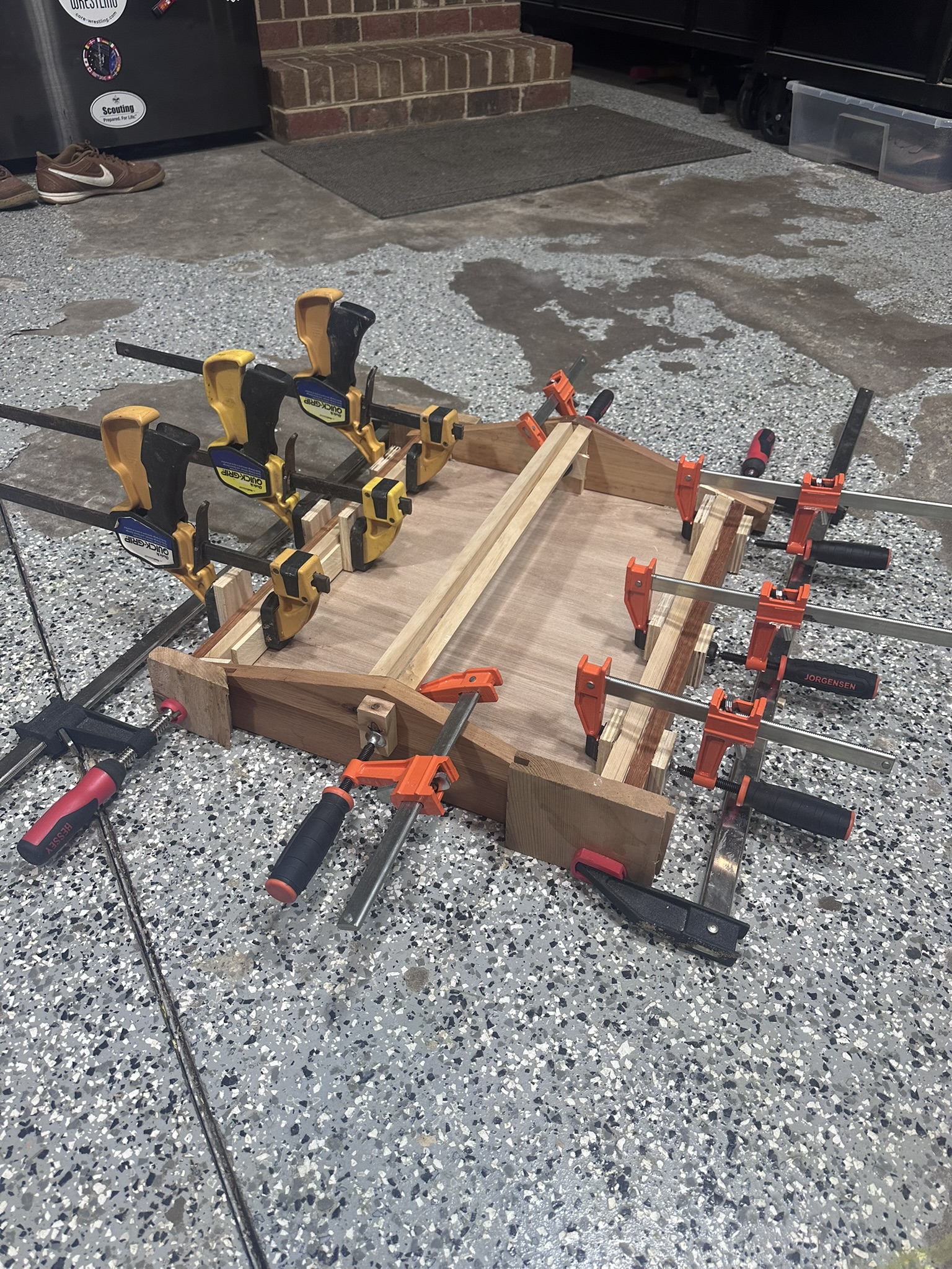
Roof assembly all clamped up with interior supports
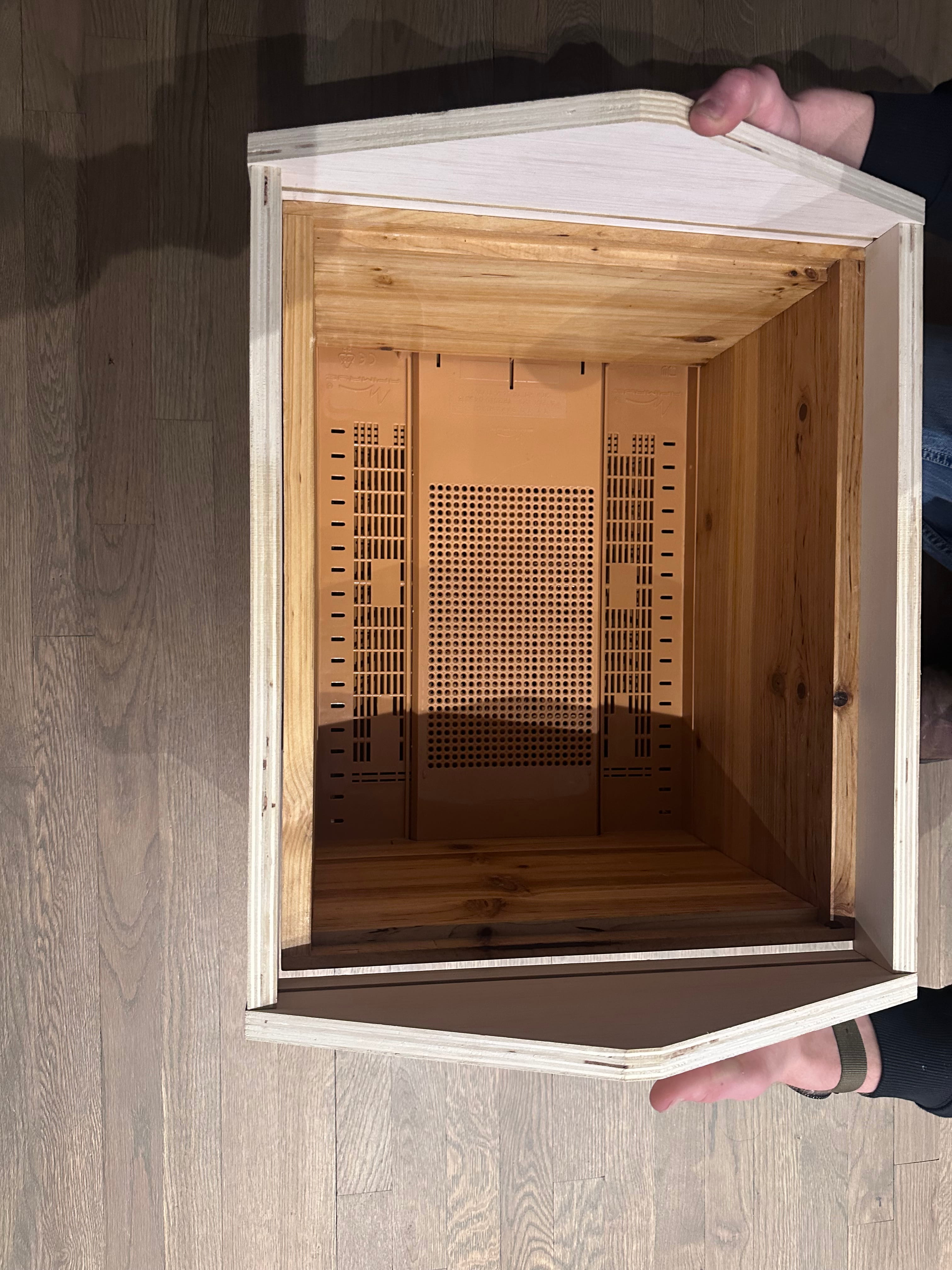
After it dried I removed all the clamps and tested the fit on my bee hive box — and it fit perfectly.
Roof Board & Copper: After that I got some thicker plywood for the roof, which I hope to wrap with a thin sheet of copper to give it a nice look. The copper will also provide a bit of heat in the winter for the bees, and it looks really cool. More on this will be added here as I continue the build.
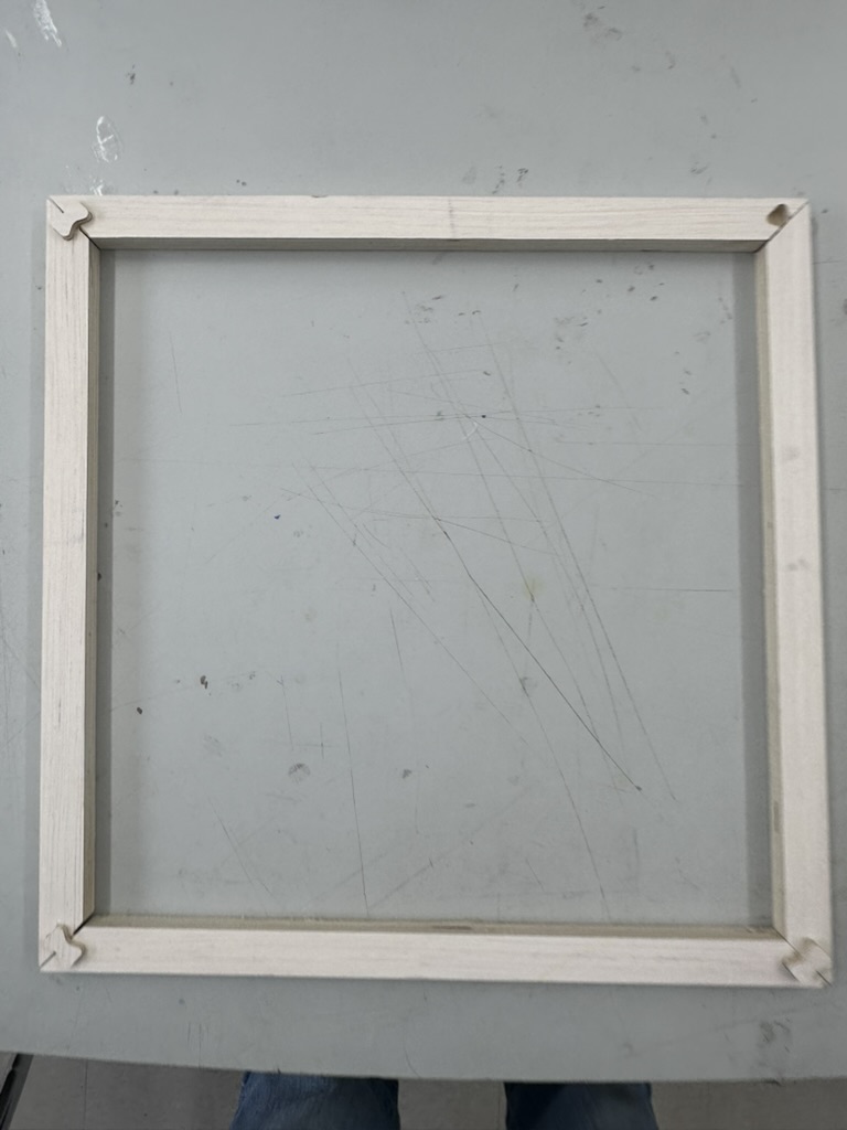
For the inner cover, I attempted dovetail key miter joints on each corner. All four corner pieces are cut at 45 degrees on the CNC, and each joint has a slot for a separately cut key that locks the miter together. The idea is that the key adds mechanical strength to what would otherwise be a weak glue-only miter joint.
This joint took a very long time to get working. I kept running into problems with the vectors exported from my Fusion file — the toolpaths wouldn't generate cleanly, and I had to go back and fix the geometry multiple times.
Inner cover V1 — dovetail key miter joints. The joints came out weaker than expected.
The finished result didn't turn out quite as good as I hoped. The joints came out a bit weak, and I think this type of joint requires extreme precision to pull off well on a CNC. For my final project, I think there are much better joint options I could use in place of this.
Camera Housing
3D-printed entrance piece designed in Fusion 360, houses the cameras at the hive entrance.
The hive entrance will have a camera mounted inside the 3D-printed housing to monitor bee activity going in and out. The camera is powered by a Raspberry Pi 5, which gives high-quality video capture at the entrance.
A comprehensive sensor array for internal and external environmental monitoring, designed with bee-safe placement.
Temperature Monitoring: Internal and external sensors for climate control assessment
Humidity Sensors: Track moisture levels critical for bee health and honey curing
Weather Integration: Pairs with local forecasts to recommend optimal times for harvest or feeding
Hardware — Sensor Components
Adafruit SHT45 with PTFE Membrane (×3)
The primary environmental sensors for the hive are Adafruit Sensirion SHT45 precision temperature and humidity sensors with PTFE filter membranes. The PTFE membrane protects the sensor element from water, condensation, and contaminants — critical for the high-humidity environment inside a beehive. I have 3 sensors — one per hive box — to monitor temperature and humidity gradients at different levels.
Interface: I2C
Temperature accuracy: ±0.1°C
Humidity accuracy: ±1% RH
PTFE membrane: Waterproof protection for harsh environments
Quantity: 4 (multi-zone monitoring)
Real-Time Data Logging
All sensor data is tracked and logged in real time. Connect from your smartphone or other device to view live readings, historical trends, and receive alerts wherever you are.
Communication — Power over Ethernet (PoE)
Instead of wireless WiFi connectivity, I decided to use Power over Ethernet (PoE) for the Smart Beehive system. A single Ethernet cable runs from the house to the hive, carrying both data and power — eliminating the need for batteries, solar panels, and WiFi hardware at the hive.
Why PoE Instead of WiFi?
No batteries needed: Batteries for outdoor hive use are expensive and need regular replacement. PoE delivers power directly over the Ethernet cable.
No solar panel needed: I calculated I would need a 140W solar panel to keep the system running — that's a large, expensive panel to mount near a beehive. PoE eliminates this entirely.
Reliable connection: A wired Ethernet connection is more reliable than WiFi over 500 feet, with no signal dropoff or interference issues.
Scalable to 5 hives: The PoE setup has the capacity to run up to 5 hives, making it easy to expand the monitoring system as I add more hives.
Simpler setup: One cable handles both power and data — no need for a UniFi access point, Alfa WiFi adapter, external antenna, or battery/solar system.
Software
Remote Monitoring
Access hive data from any device with real-time alerts and notifications
Data Visualization
View historical trends and live sensor readings
Alerts
Notifications for feeding, harvesting, and health concerns
Multi-Hive Management
Scalable interface for managing multiple hives
Raspberry Pi 5 Setup & Configuration
Detailed setup notes for the Smart Beehive Raspberry Pi 5 — hardware, wiring, configuration steps, and the live stream server. This documents how the cameras and sensors are wired up and how the streaming software runs.
Electronics Parts List
Complete list of electronics components for one Smart Beehive unit. Notes explain why each part was chosen and any gotchas.
Part
Notes
Raspberry Pi 5 (8 GB)
4 GB also works; 16 GB is overkill
PoE+ HAT (official)
Optional but recommended — one cable for power + network
MicroSD card, 32 GB+ A2
The image is ~3 GB compressed; 32 GB leaves room for the offline buffer
TCA9548A I²C multiplexer
Lets you stack multiple SHT45 sensors on one I²C bus
1–3× SHT45 sensors
Per hive box: brood box, super, exterior
4× 50 kg load cells + HX711
Wheatstone bridge wiring; ~200 kg total capacity
MG996R servo + ≥470 µF cap
Cap is mandatory — prevents voltage dip on the Pi's 5 V rail during servo inrush current. Without it, the Pi can brownout or reboot when the servo moves.
5 V cooling fan with tach
For Pi thermal management, not hive ventilation
2× LED banks (red + white)
Mutually exclusive: red for night, white for day
1–2× Pi Camera Module 3 Wide
IMX708 sensor; CSI0 and/or CSI1
Current Configuration
Board: Raspberry Pi 5 Model B Rev 1.1 (8 GB)
OS: Raspberry Pi OS 13 (Trixie), kernel 6.12.75 aarch64
Power: Waveshare PoE HAT (F) via Ethernet
Cameras: 2× IMX708 Wide (Camera Module 3 Wide) — Camera 0 on CSI port i2c@88000, Camera 1 on CSI port i2c@80000
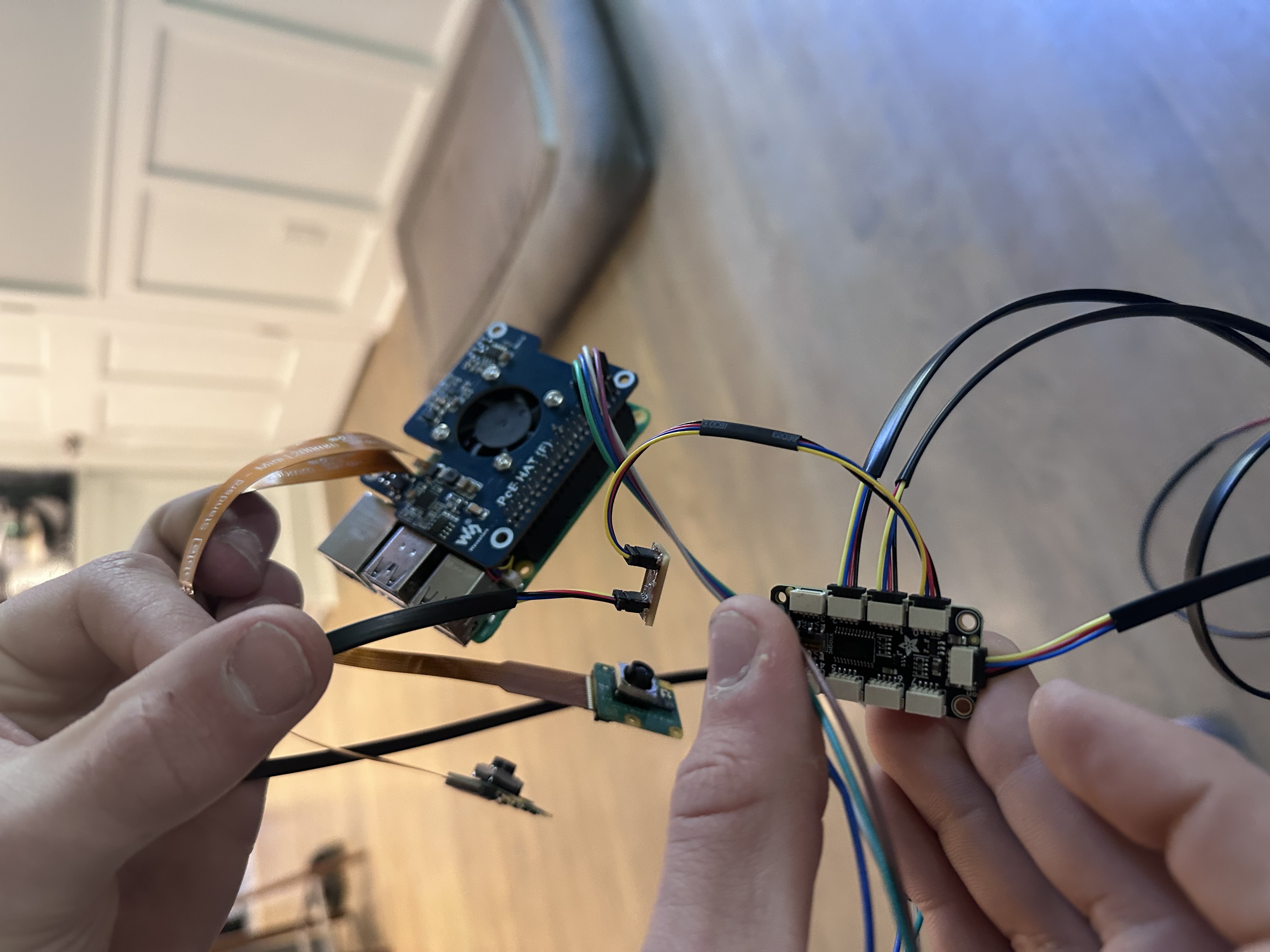
Sensors: 3× SHT45 (temperature/humidity) via Adafruit PCA9548 I²C multiplexer
Hostname:smartbeehive.local
Wiring — PCA9548 I²C Multiplexer
Pi GPIO
Mux Pin
Wire Color
3V3
VIN
Red
GND
GND
Black
GPIO 3 (SCL)
SCL
Yellow
GPIO 2 (SDA)
SDA
Blue
SHT45 Sensors
Sensor 1 → Mux Channel 0
Sensor 2 → Mux Channel 1
Sensor 3 → Mux Channel 2
Configuration Steps
1. Enable I²C
I²C was disabled by default on a fresh install. Enabled with:
sudo raspi-config nonint do_i2c 0
sudo reboot
Verify the multiplexer is detected:
sudo i2cdetect -y 1
# Should show 0x70 (PCA9548 mux)
2. Scan Sensors Through the Mux
Loops through each of the 8 mux channels and looks for an SHT45 (address 0x44) on each one:
for ch in 0 1 2 3 4 5 6 7; do
  sudo i2cset -y 1 0x70 $((1 << ch))
  result=$(sudo i2cdetect -y 1 | grep "44")
  if echo "$result" | grep -q "44"; then
    echo "Channel $ch: SHT45 found at 0x44"
  fi
done
sudo i2cset -y 1 0x70 0x00
3. Fan Test (Waveshare PoE HAT F)
The PoE HAT's onboard fan can be controlled via the cooling thermal subsystem:
# Set fan speed (0-4)
echo 4 | sudo tee /sys/class/thermal/cooling_device0/cur_state

# Read RPM
cat /sys/devices/platform/cooling_fan/hwmon/hwmon2/fan1_input

# Reset to auto
echo 0 | sudo tee /sys/class/thermal/cooling_device0/cur_state
4. Camera Test
Quick capture test to verify both cameras are working (use rpicam-* on Trixie, not libcamera-*):
The streaming script (~/stream.py) is built on top of the MJPEG HTTP server I developed in Week 11 — Networking and Communications. It adds sensor reading on top of the dual-camera streaming:
Streams both cameras at 1080p via MJPEG (using rpicam-vid)
Reads all 3 SHT45 sensors every 2 seconds via the I²C multiplexer
Serves a web dashboard on port 8080 with cameras + live sensor readings
SSH tunnel from a remote network:ssh -L 8080:localhost:8080 <username>@<pi-ip> then open http://localhost:8080
Endpoints
Path
Description
/
Dashboard (cameras + sensors)
/snap0
Camera 0 JPEG frame
/snap1
Camera 1 JPEG frame
/sensors
JSON: [{"temp": x, "hum": y}, ...]
SSH Access
SSH key auth from my Mac. Sample ~/.ssh/config entry:
Host smartbeehive.local
    User <username>
    IdentityFile ~/.ssh/id_ed25519
Cloud Dashboard — hive-monitor.com
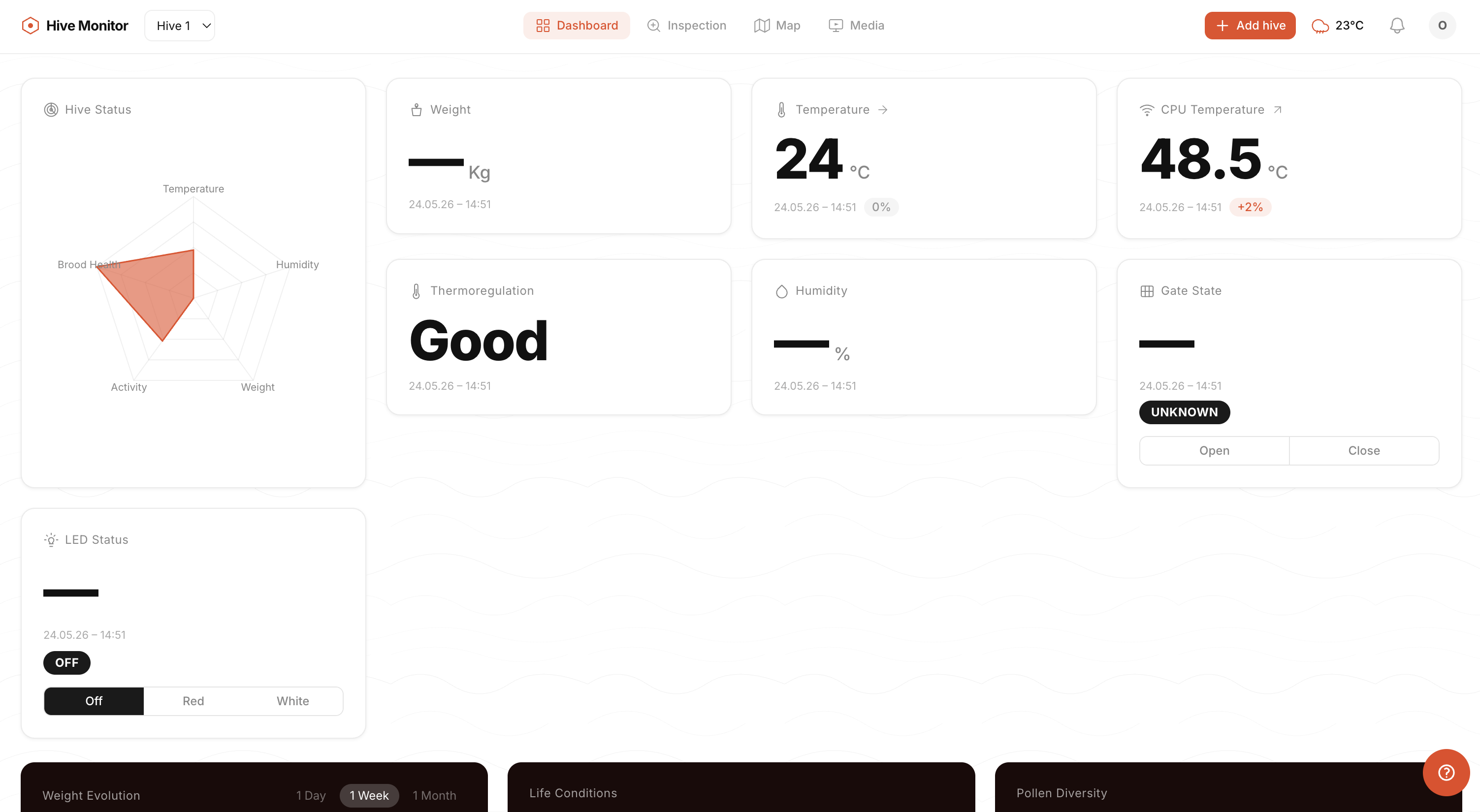
The system now uses a full cloud-hosted web application. The current development version is live at dev.hive-monitor.com while I finalize the production deployment. The Pi pushes data to AWS IoT Core over MQTT, which routes it to the backend and web dashboard. Currently live and reporting:
Real-time SHT45 sensor data (temperature + humidity from all 3 sensors)
Pi CPU temperature monitoring (critical for thermal management)
Still in progress: UI polish, camera feed integration, historical graphs, alert notifications. The goal is a consumer-ready product — currently working on cost reduction and UX for non-technical beekeepers. See Week 15 — Interface and Application Programming for full dashboard build documentation.
hive-monitor.com dashboard — live sensor data with interactive graphs. See Week 15 for full framework documentation.
Product Vision
No one is currently selling a complete plug-and-play smart hive monitor. The existing DIY projects on GitHub are hobby-grade and not packaged for consumers. I'm building this as a real product — the Pi 5 is overkill for production and the BOM needs cost optimization, but the proof of concept demonstrates the full end-to-end experience. Summer 2026 focus: cost reduction, UX polish, and field testing with real beekeepers.
Cost Breakdown
All costs documented during the build. Items are categorized by how they scale: per-hive costs apply to every hive built, one-time tool costs are a single investment, and shared supply costs can be spread across multiple hives.