Week 10 Output Devices
Link to Group Site
This week, I decided to use a DC motor as my output device. In my final project, I will have multiple fans driven by motors.
My board from input week has a DC motor, which fits the requirements for this week. I will still include the process of creating the board.
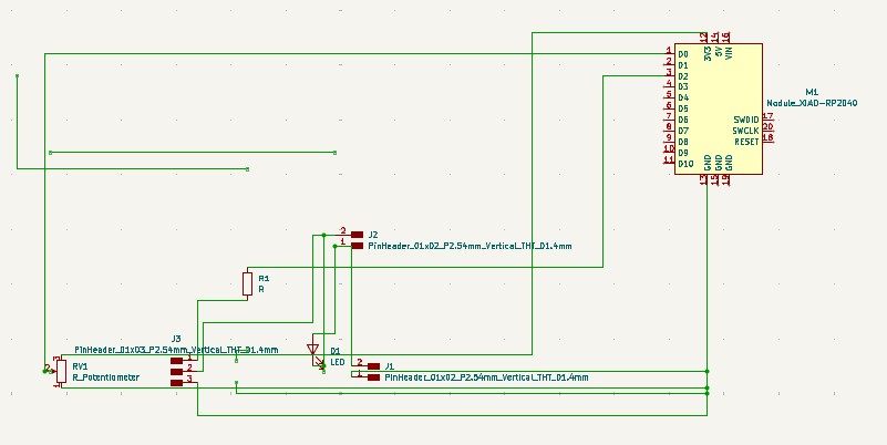
I created this schematic in KiCad. The upper two pin connector is for the motor. The lower two pin connector is for the power supply. The 3 pin connector is for a mosfet.
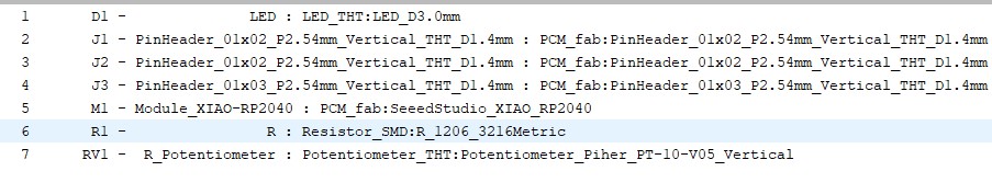
These are the footprints I used. The LED footprint is for the diode. The diode prevents EMF, which can damage my microcontroller.
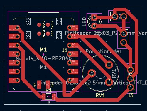
I imported all of the footprints into the pcb editor, arranged them, then sketched the traces. I gave my board larger traces because in the past, some of my traces ripped away during the soldering process. I made my board compact to save on material cost.
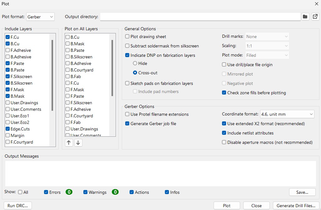
After I designed my board, I went to file, fabrication outputs, then gerbers. These are the settings I used to generate my gerbers. I only needed the front copper gerbers and the edge cut gerbers, but ended up generating gerbers for more because I forgot to uncheck those boxes. Gerbers only generate the traces, so I needed to generate the drill files for the through holes.
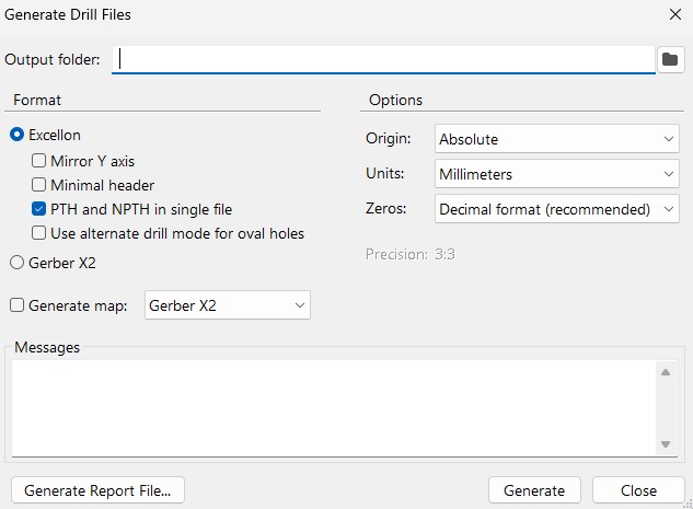
I went to the same place to generate the drill files. File, fabrication outputs, then drill files. These are the settings I used to generate the drill files.
**Click Here to download my KiCad file
(The Gerbers are in the KiCad file, the .drl file is not)
**Click Here to download the .drl file
Makera Cam Settings
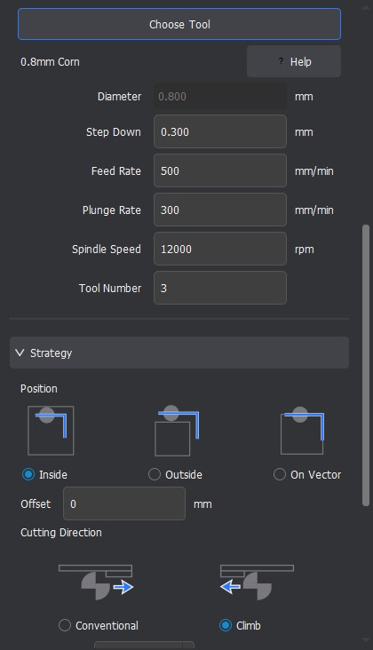
I used these settings above in Makera CAM for my traces. This toolpath goes with the traces gerbers.
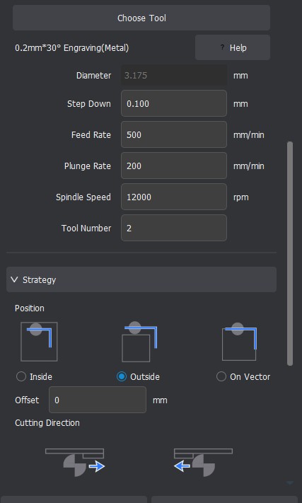
I used these settings above in Makera CAM for my outline. This toolpath goes with the outline gerbers.
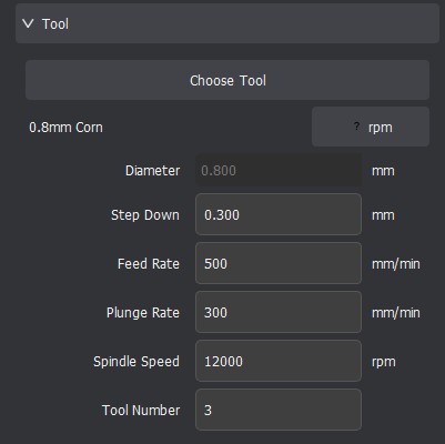
I used these settings in Makera CAM for my through holes. This toolpath goes with the .drl file.
After I created the toolpaths, I generated the gcode.
Click Here to Download the GCode
I milled the board again this week, because last week, I had some issues with the diode.
Milling, Soldering, and Populating the Board
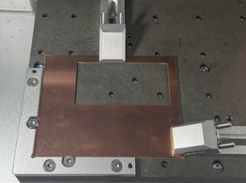
I put a copper stock, like this, the bed, with double sided tape under it. I then finally clamped it down.
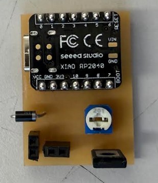
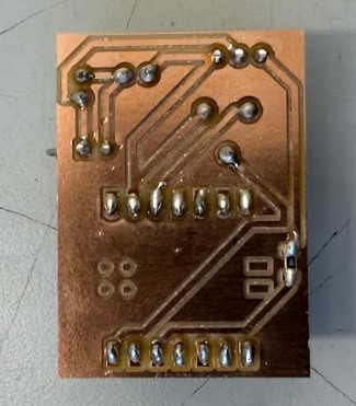
This is the board after soldering and populating. As you can see, My soldering skills were much better this week compared to last week.
Code
I used the same code I used during week 9.
from machine import Pin, ADC, PWM
import time

# Potentiometer on A0 (GPIO 26)
pot = ADC(Pin(26))

# TIP120 base driven from D2 (GPIO 28)
motor = PWM(Pin(28))
motor.freq(2000)  # TIP120 works better at higher PWM frequency

while True:
    val = pot.read_u16()
    motor.duty_u16(val)
    time.sleep(0.01)
Output Device Specs
Click Here to access a website with the output device
Specs
Rated Voltage: 3-6V Continuous No-Load Current: 150mA +/- 10% Min. Operating Speed (3V): 90+/- 10% RPM Min. Operating Speed (6V): 200+/- 10% RPM Torque: 0.15Nm ~0.60Nm Stall Torque (6V): 0.8kg.cm Gear Ratio: 1:48 Body Dimensions: 70 x 22 x 18mm Wires Length: 200mm 28 AWG Product Weight: 29g / 1.02oz
Testing the Output Device
As you can see, the motor spins. Its speed is able to be increased and decreased by PWM.
Reflection
This week wasn't to difficult. I put this week off a while because of machine week. When I started the week, I realized my board from week 9 met the requirements. I still milled the board again, but the process was very smooth because I had done it before. The group work was also very easy.
Reflection about Group Project
We went into this group project very confident. However, the team actually had some issues with the multimeter. One of the probes was connected to the wrong hole on the multimeter. Because of this, the multimeter would not detect how much current the motor was drawing. Once we figured this out, it wasn't to hard. Recording the test was hard. We had to have one person filming, One person using the multimeter, and one person changing the motor speed.