Fab Academy 2026 Final Project
Desktop Wind Tunnel
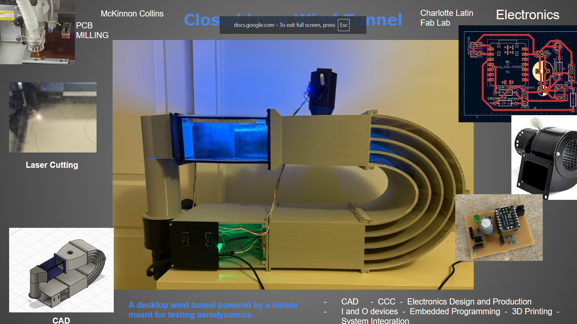
This is my Desktop Wind Tunnel
Weeks:
Computer Aided Design
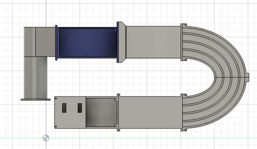
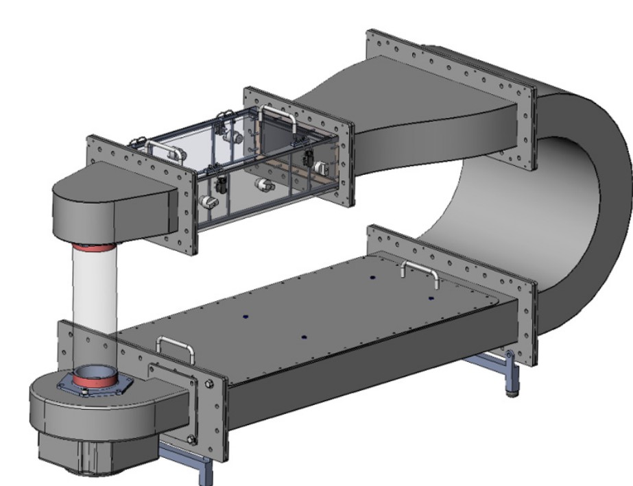
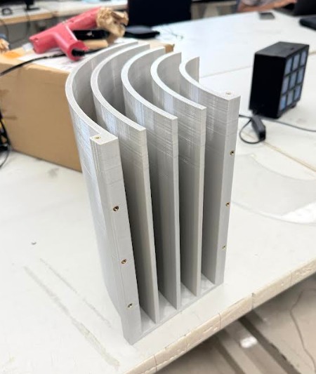
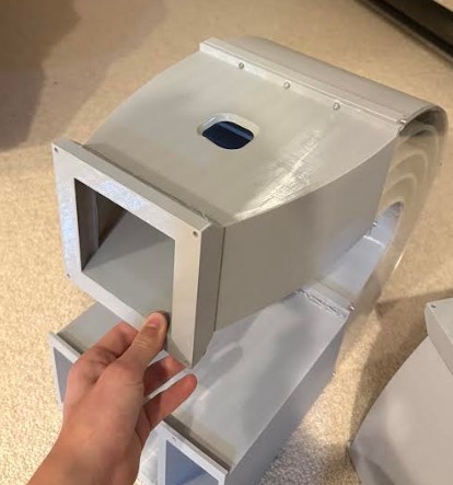
I made this model in Autodesk fusion. The design is a closed loop wind tunnel featuring all the components of a wind tunnel like a gradual diffuser, contraction cone, turning vanes, and a clear testing chamber.
Above are some more angles of the wind tunnel. The hole at the top of the contraction cone is for the mist injector.
The wind tunnel was very easy to design, it is just a bunch of sketches and extrusions.
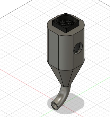
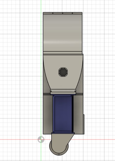
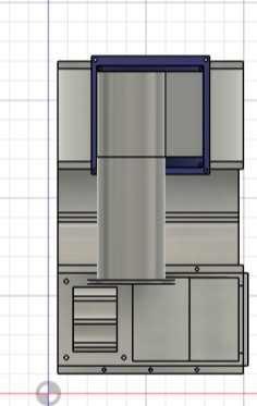
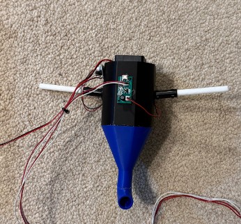
This is the mist maker I made in Autodesk fusion. On it is a small fan helping push the mist into the tunnel, along with a honeycomb to cancel fan swirling.
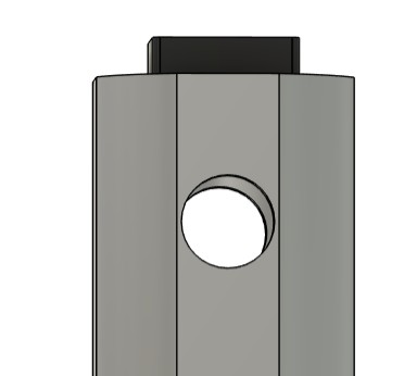
On the side of the main chamber in the mist maker are two holes. Two ultra sonic mist makers can be pressed into these holes where they can inject mist into the main chamber.
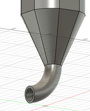
On the bottom is the spout, where the mist from the main chamber is blown by the fan into the spout. The spout then leads to the wind tunnel. The spout acts as a Venturi.
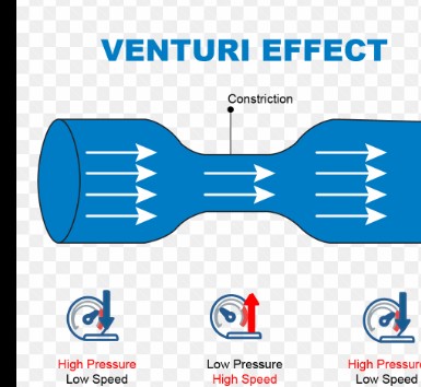
The main chamber acts as the first high pressure zone, with a fan intaking air, and mist being injected. The spout acts as the low pressure and high speed area. The high speed is crucial because the air in the wind tunnel is traveling at a very high velocity. Lastly, the wind tunnel itself acts as the second low speed and high pressure zone.
CAD FILES
Click Here to Download my CAD Files
In this folder, I have all of my cad models as individual STL files.
Computer Controlled Cutting
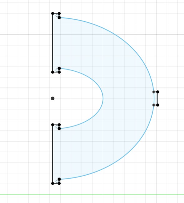
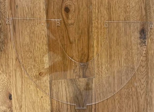
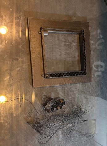
First, I wanted to cut a clear acrylic side panel to go over the turning vanes becuase small objects could get trapped in that area. Without a clear side panel, I wouldn't be able to see if anything is stuck. Additionally, if something did get stuck, I could easily remove the side panel to gain access to the area.
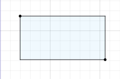
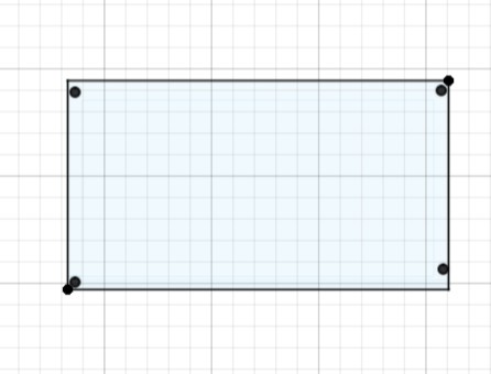
These two rectangles are the side acrylic and top acrylic viewing windows. The top acrylic window has holes where screws will be able to hold it down. The top window can be removed to place an object in the wind tunnel.
After designing, I exported each sketch individually as .dxf files.
Click here to download the side panel
Click here to download the top window
Click here to download the side window
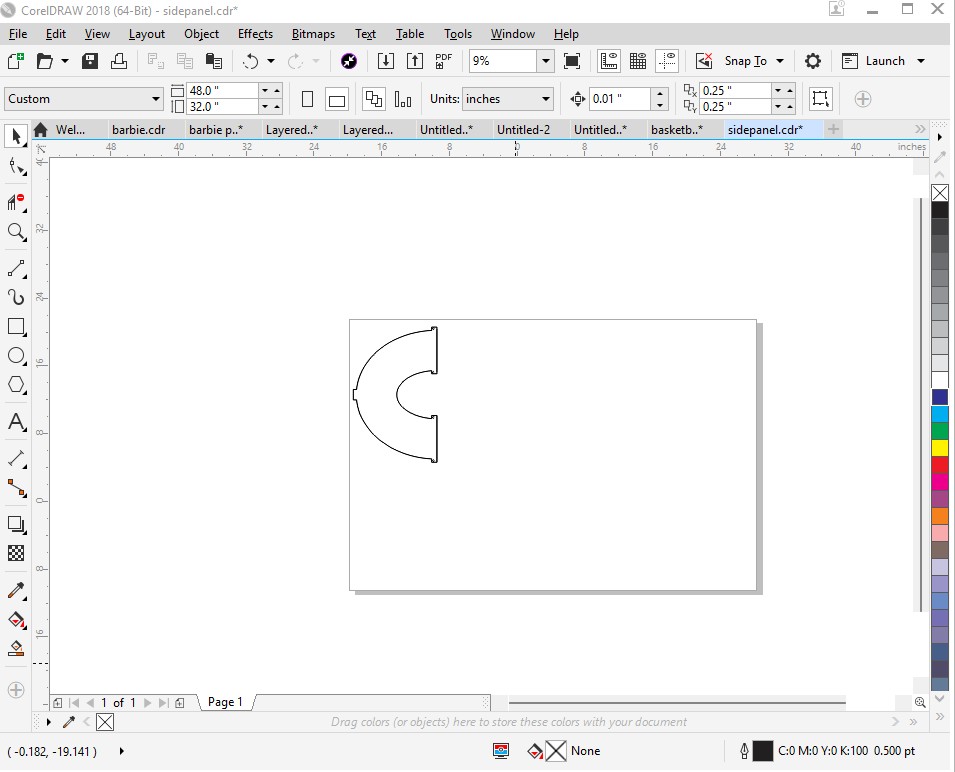
After exporting, I imported each dxf file by itself into Corel Draw 2018. Above you can see I imported the side panel into Corel Draw.
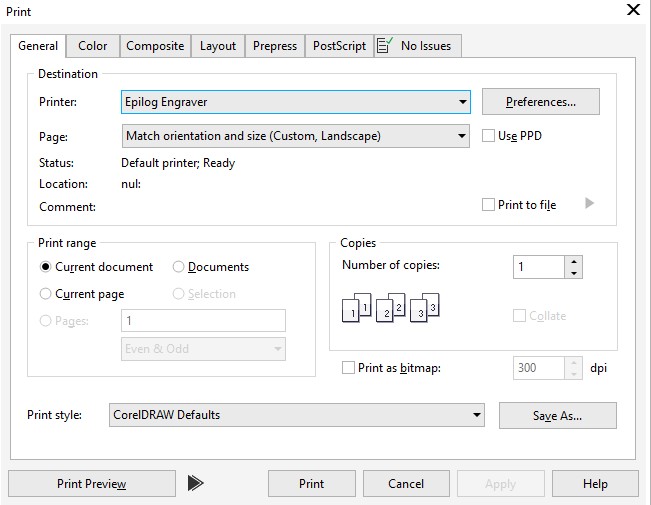
Once the file is into Coreldraw, I pressed file, then print. This menu came up. I selected the Epilog Engraver as the printer. Then, I pressed the print button
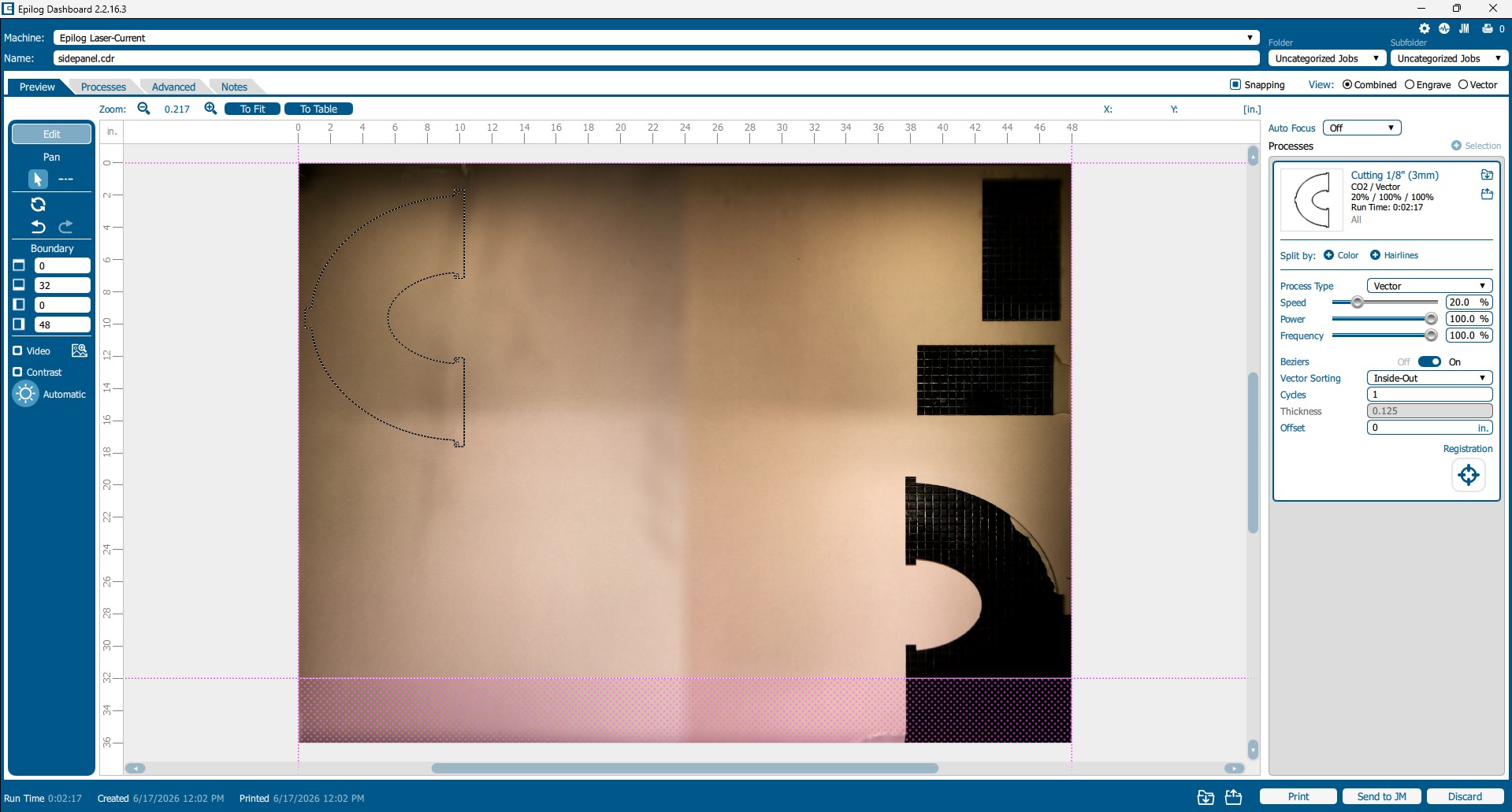
Once I pressed print, this menu came up. I alligned the design onto an open area of acrylic. On the side you can see the settings I used. They are the recommended settings for 3mm acrylic.
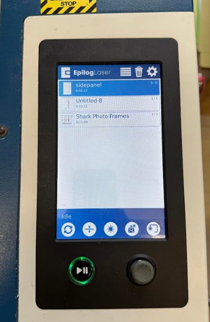
I pressed print at the bottom, then the job was sent to the controller which can be seen above.
I selected the side panel job, then the lasercut automatically start.
Before running, make sure to focus the laser
As you can see here, the Epilog laser is cutting my side panel.
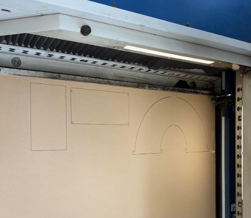
These are all my pieces after laser cutting.
I used the exact same process to cut both viewing windows
This is my side panel after cutting and removing the film.
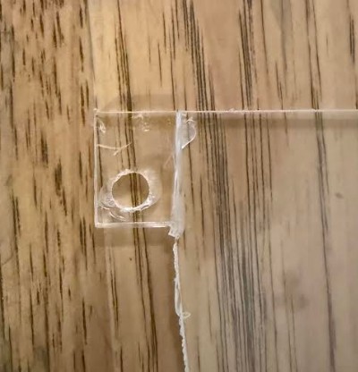
When removing the small holes, I accidently snapped off the area surrounding the hole. The laser didn't quite cut all the way through so I had to use a lot of force removing the holes. Luckily, I was able to glue this piece back together.
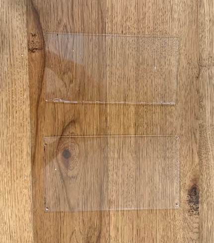
These are both viewing windows. They had no issues and I was able to remove the holes from them with ease.
Embedded Programming
For this project, I chose the XIAO RP2040 from Seeed Studio because of small size and large quantity of programmable input and output pins.
Programming
To program the microcontroller, I need an IDE and a suitible programming language. Because the microcontroller is a raspberry pi, I will use micropython code, compared to C with an ESP32.
Previously in the course, I set up Visual Studio Code for programming RP2040 chips with micropython.
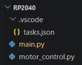
This is my project tree in VScode, with RP2040 being the name of the project. The tasks.json file allows vscode to compile and upload code to my microcontroller.
Here is the tasks.json code:
{
  "version": "2.0.0",
  "tasks": [
    {
      "label": "Upload to Pico",
      "type": "shell",
      "command": "mpremote connect auto fs cp main.py : + reset",
      "group": "build",
      "presentation": {
        "reveal": "always",
        "panel": "shared"
      }
      }
    ]
    }
Now in VScode, you can go to terminal, Run Task, then Upload to Pico. VScode will compile and upload your micropython script to the pico.
This is the code I used.
from machine import Pin
import neopixel
import time

# ===== NEOPIXELS =====
NUM_PIXELS = 5
NEO_PIN = 28
NEO_SWITCH_PIN = 27

COLOR_ON = (180, 255, 255)  # bright cyan-white

np = neopixel.NeoPixel(Pin(NEO_PIN), NUM_PIXELS)
neo_switch = Pin(NEO_SWITCH_PIN, Pin.IN, Pin.PULL_UP)

# ===== MIST MAKER =====
mist = Pin(29, Pin.OUT)
mist_switch = Pin(26, Pin.IN, Pin.PULL_UP)

def set_pixels_on():
    np.fill(COLOR_ON)
    np.write()

def set_pixels_off():
    np.fill((0, 0, 0))
    np.write()

# Start with everything off
set_pixels_off()
mist.value(0)

# ===== MAIN LOOP =====
while True:

    # NeoPixel control (GPIO27)
    if neo_switch.value() == 0:
        set_pixels_on()
    else:
        set_pixels_off()

    # Mist maker control (GPIO26)
    if mist_switch.value() == 0:
        mist.value(1)
    else:
        mist.value(0)

    time.sleep_ms(10)
(This code was Generated with AI, I will go into the process later in electronics design).
I pasted this code into main.py, then uploaded to pico, however it did not work the first time.
Because I used a brand new microcontroller, it had never been flashed with micropython.
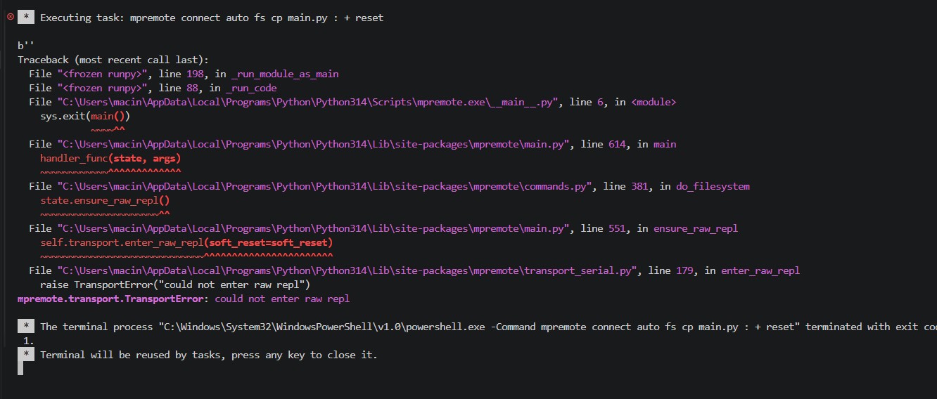
This was the error message that kept coming up in the vscode terminal.
To fix, go to This Website and download the most recent .uf2 file near the bottom of the page. These files are specifically for the XIAO RP2040.
Once you download the .uf2 file, the file is in the downloads folder, not the microcontroller. To transfer it into the microcontroller you need to use the boot button.
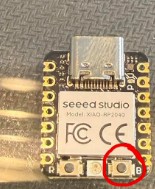
Before plugging the microcontroller in, hold down on the boot button (circled in red). Once you are holding down the boot button, plug the microcontroller into the computer via a usb-c cable WITH data transfer capabilities. (This will not work with a regular usb-c cable). Once the microcontroller has been plugged in with the boot button held down, you can release the button.
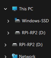
The microcontroller should appear as an external drive with the name you see above. If you see two devices (like mine), that is perfectly fine.
Drag and drop the .uf2 file into the the microcontroller drive. (Dropping the file into the top device has always worked for me when two devices show up).
After flashing, the device should disappear and be ready for programming.
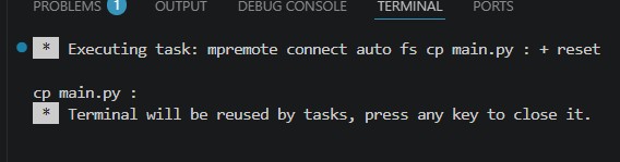
When you run the Upload to Pico in VScode, this message should come up in the terminal. This message means the code has been successfully uploaded to the pico.
3D Printing
For this project, I will mainly use the Bambu A1 printer, along with small use of the Elegoo Neptune 4 Pro printer.
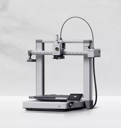
This is the Bambu A1 printer. It features automatic bed leveling which makes it a game changer. It is very precise and rarely fails with a reasonable print.
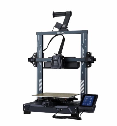
This is the Elegoo Neptune 4 Pro printer. It has a smaller print bed (225mm x 225mm) compared to the bambu a1 (256mm x 256mm). Both printers however have the same build height. The Elegoo Neptune 4 Pro is older and is more prone to failure. It additionally struggles with supports. I will only be using it for simple prints.
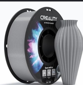
I will be using this grey Creality CR-PETG filament. I have found this filament prints extremely well on the Bambu A1 printers. PETG is also stronger than PLA, while being the same price (if not cheaper) and prints just as well.
Slicers
For the bambu a1, I will be using the Bambu Studio slicer. Because it is made for Bambu printers, it slices the best and allows the user to be able to wirelessly send prints to the printer.
For the Elegoo Neptune 4 Pro, I will use the Elegoo Cura 5.6.0 slicer. This is the newest version and allows many printers to be able to use it. Because it was made by Elegoo, it will naturally be the best for the printer. This slicer does have capibility for wireless sending of prints, however I choose to send my prints via a USB flash drive to the Elegoo Neptune 4 Pro printer.
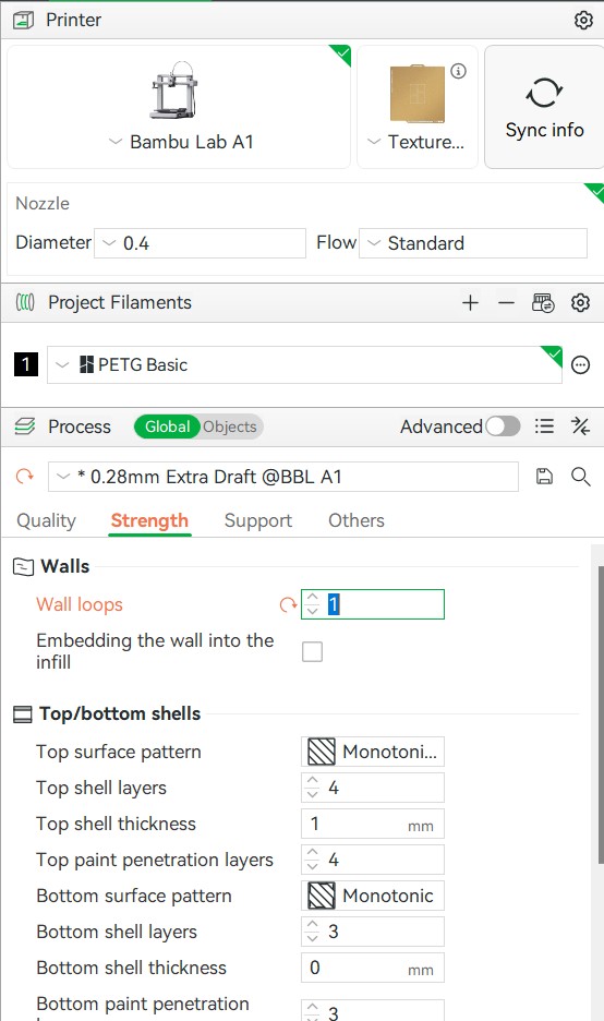
I used these settings in bambu slicer. Because my wind tunnel is mainly 3d printed and very large, print time was a problem for me. I had to go with a 0.28mm diameter preset, 1 wall loop, along with 5 percent infill on all my large prints. Without that, I wouldn't have enough time to complete my project before presenting to Dr. Gershenfeld and the rest of the Fab Academy. I avoided using supports on all my large prints which helped save time too.
In the future once I have completed Fab Academy, I will reprint all the parts with a finer preset and more wall loops/infill to increase longevity.
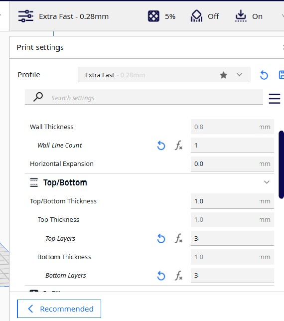
Similar to the bambu settings, I also used a 0.28mm diameter preset, 1 wall loop, and 5 percent infill.
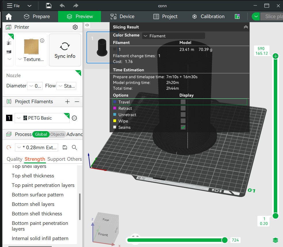
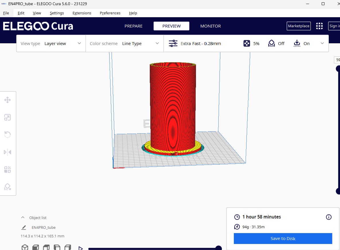
I sliced the same model in bambu lab (on the top) and elegoo cura (on the bottom) with the same settings. The time it takes the Elegoo Neptune 4 Pro to print the model is actually quicker than the bambu a1. However, the Bambu a1 prints better and doesn't fail as much as the Elegoo Neptune 4 Pro. Additionally, the Elegoo printer doesn't have the time consuming pre print calibration that the bambu a1 does.
Here, both printers are printing parts for my project. The elegoo printer has a slightly quicker speed.
On this print with the Bambu a1, I did not use supports. as you can see, the area got messed up, however it still worked. I will definitely reprint this later with supports. This defect was not the printers fault, it was a user error.
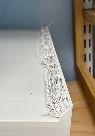
This defect however was the printers fault. When the bambu printer lays down a final layer next to a vertical part that is still being printed, it lays out filament in a grid pattern, not printing half grids. Because 5% infill creates such large grid sizes, there was a large open space next to the vertical piece. The printer was essentially trying to make a bridge, if the bridge was only connected to the ground on one side. This is less of a physical printer issue and more something that can be fixed in the software.
Overall, the Bambu printer did a very good job printing the project.
I tried printing the main chamber on the bambu in PLA, since PETG temperatures are near the maximum temps of the Elegoo printer.
The print itself did fine, however the supports (which were necessary for the chamber), did not do so well. The small surface area of the supports constantly caused the supports to fail, which would make me have to stop the whole print. I keep tweaking the settings to try to get the supports to print right, however nothing worked. All other attempts ended up like this one above. I eventually gave up on printing the chamber with this printer.
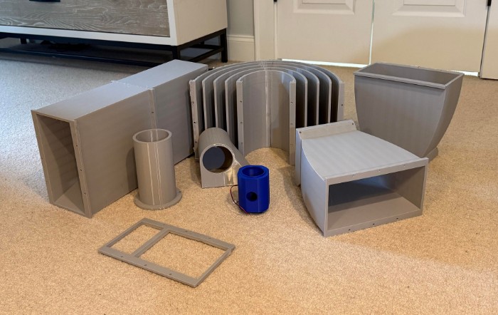
These are all of my PETG prints along with a print for the mist maker system.
Electronics Design
For this project, there are 3 main electronic components which need to be controlled. First is the mistmaker, second are the neopixels, and last is the blower.
Mist Maker
The mistmaker requires 5V to function properly, however the GPIO pins on the RP2040 only produce 3.3V. I could wire the 5V to the microcontroller's VCC pin, however since I will be using a 5V PSU for this project, I didn't want to put extra stress on the microcontroller. To be able to control the mistmaker, I need to switch the low side, since the the mistmakers 5V will be directly wires to the PSU. Luckily, my lab has some JE802 low side switching transistors which I was able to use.
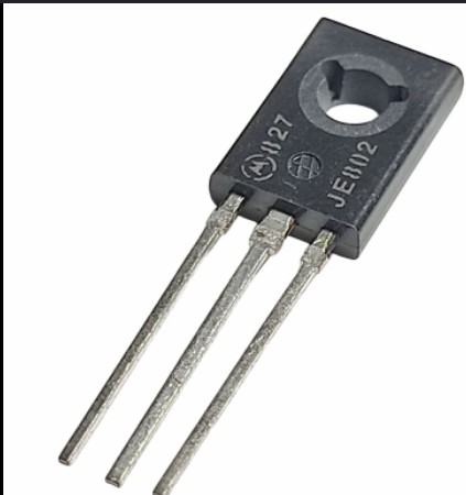
This is the transistor. Low side switching means the transistor is designed to turn the ground on and off.
The pinout goes Emitter, Collector, Base, right to left. With the transistor, the emitter. The base acts as a control valve, regulating how many charge carriers flow from the emitter source to the collector output.
Neopixels
Neo pixels are a lot easier to control. I wired the VCC to 5v, GND to GND, and the data pin to a GPIO pin on the RP2040.
Inputs
For inputs, I got pushbuttons and wired them from a GPIO pin to GND. These inputs serve as the on and off for the mist maker and neo pixels.
Blower
The blower doesn't run off 5V DC, it runs off American AC (120V, 60HZ). I got a 3 prong power cord and wired it to the PSU and Blower. This way, when the PSU turns on to power all the electronics, the blower also turns on.
Design
To design my PCB, I used KiCad.
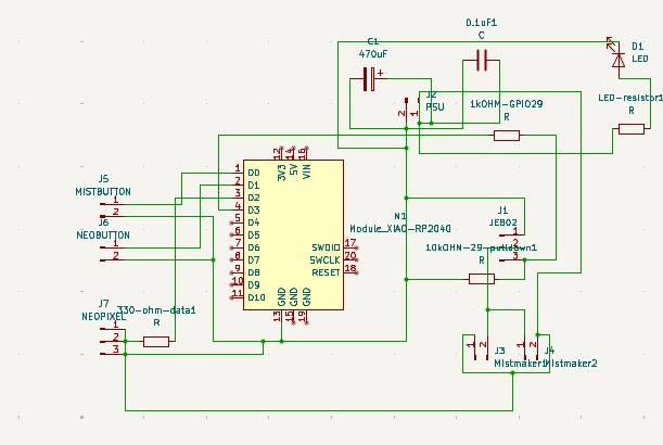
I made this schematic in KiCad. I used 2 pin connectors to connect the mist makers, psu, buttons, and neopixels. I used a 3 pin connector for the mosfet. (I couldn't find a suitible component and I did not feel the need to download a component when the 3 pin connector works). The resistors are mainly for circuit protection and the capacitors are mainly for power filtering. The LED is a power indication LED to indicate if the power supply is working.
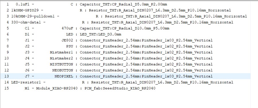
These are the footprints I used. I chose through hole for the components because they feel more secure.
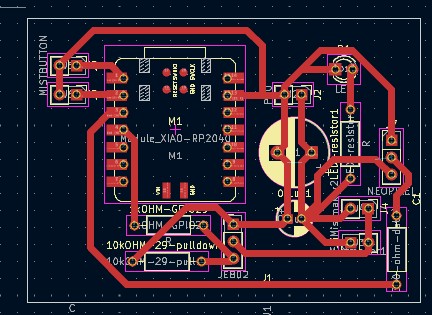
I designed this PCB in the pcb editor. I used thick traces for ease of soldering and because some components draw a lot of current. I made the PCB compact
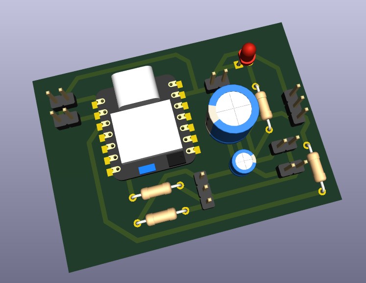
This is the 3d view of my PCB.
Code
from machine import Pin
import neopixel
import time

# ===== NEOPIXELS =====
NUM_PIXELS = 5
NEO_PIN = 28
NEO_SWITCH_PIN = 27

COLOR_ON = (180, 255, 255)  # bright cyan-white

np = neopixel.NeoPixel(Pin(NEO_PIN), NUM_PIXELS)
neo_switch = Pin(NEO_SWITCH_PIN, Pin.IN, Pin.PULL_UP)

# ===== MIST MAKER =====
mist = Pin(29, Pin.OUT)
mist_switch = Pin(26, Pin.IN, Pin.PULL_UP)

def set_pixels_on():
    np.fill(COLOR_ON)
    np.write()

def set_pixels_off():
    np.fill((0, 0, 0))
    np.write()

# Start with everything off
set_pixels_off()
mist.value(0)

# ===== MAIN LOOP =====
while True:

    # NeoPixel control (GPIO27)
    if neo_switch.value() == 0:
        set_pixels_on()
    else:
        set_pixels_off()

    # Mist maker control (GPIO26)
    if mist_switch.value() == 0:
        mist.value(1)
    else:
        mist.value(0)

    time.sleep_ms(10)
As I mentioned earlier, I generated this micropython code with AI. My prompt was:
I designed a PCB with a XIAO RP2040. I have two buttons, each wired from their GPIO pins (GPIO26 and GPIO27). I want the the button on GPIO26 to control the on and off output from GPIO29. GPIO29 is connected to the collector of a JE802 low side switching transistor. The transistor should function as a switch connected to a 5V external PSU. Dont worry, the grounds are tied together. The 5V will be powering a mist maker. I want the switch on GPIO27 to control the data pin of a neopixel. GPIO28 is connected to the Neopixel's data pin. I want the neo pixel to be a solid bright blue and white color.
**Click Here to Download my KiCad Project
Electronics Production
Now that I have a functioning board, the next step is to fabricate it.
I exported the edge cuts and front copper as gerber files.
Click here to download the Front Copper Gerber
Click here to download the Edge Cuts Gerber
I exported the through holes as a drill file.
Click here to download the drill file
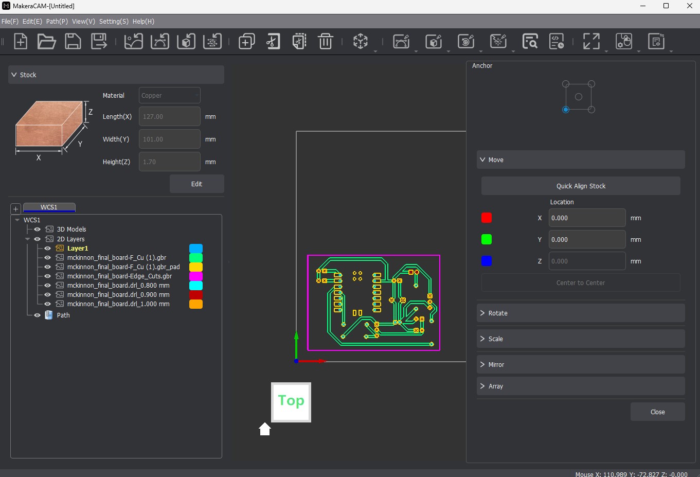
First, I imported all the gerber and drill files, the positioned them in the workspace.
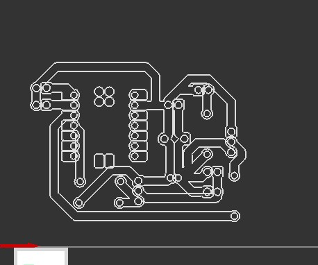
I then generated toolpaths using the contour and drill hole tools.
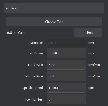
These are the settings for the 0.8mm corn bit. I used this bit to cut around the edges and drill the holes.
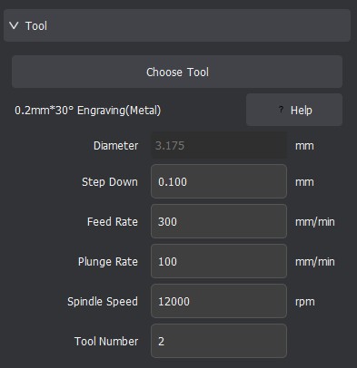
These are the settings for the 0.2mm engraving bit. I used this to cut the traces.
I then exported the toolpaths as a gcode file
Click Here to Download the Gcode file
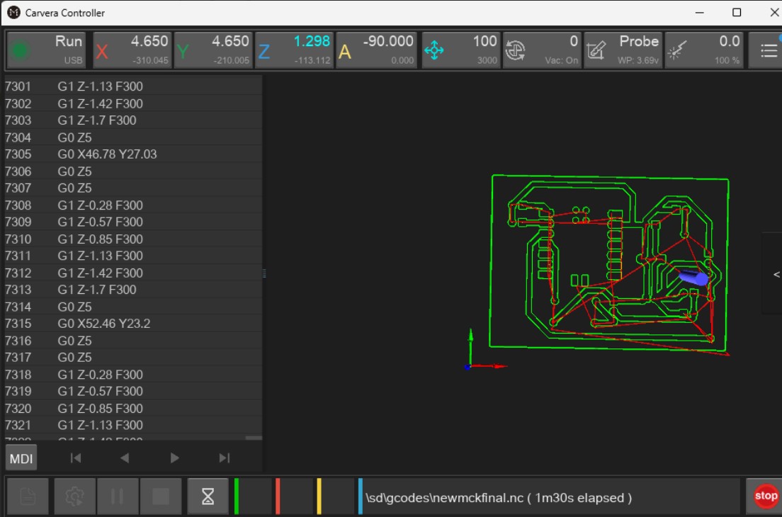
Above, I imported the gcode file into carvera controller, then sent the job to the milling machine.
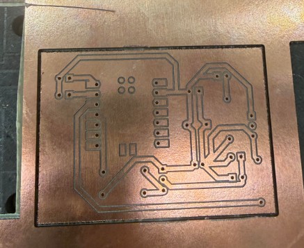
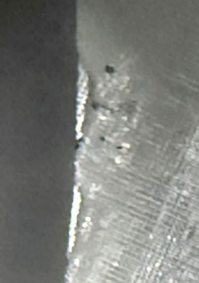
This is my board after milling. All of the traces cut cleanly through and the through holes go all the way through.
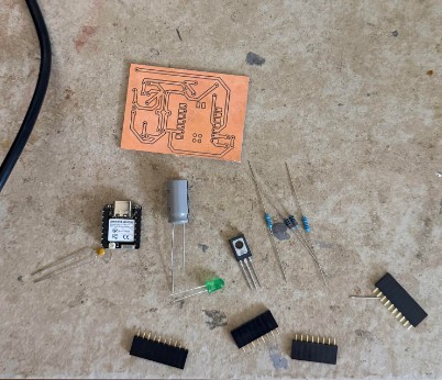
This is my board and all the components. The capacitors are mainly for power filtering, the LED is a power indicator, and the resistors are for protection. The pin connectors allow the different input and output devices to be connected while not being physically attached to the board.
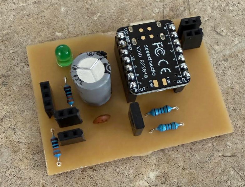
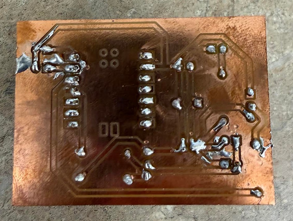
This is the front and rear of the board. I decided to change out the ceramic capacitor during the soldering process because the yellow one was to big. During the process, I accidently made a few solder bridges, however I was able to remove them.
Input Devices
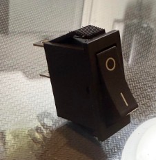
For the input device, I chose to use this generic 2 pin toggle switch. The 2 pin design makes it very easy to incorporate onto a circuit.
I used 2 of these switches.
I connected 1 end to a GPIO pin, and the other to GND. This way, the RP2040 can detect when the button has been pressed.
Output Devices
Compared to the simple input device for this project, the output devices are more complicated.
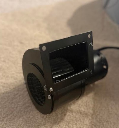
The blower above runs of American AC (120V AC 60HZ). It draws around 0.75-1.5 Amps. It consumes around 85-175 Watts of power. It produces 115-145 CFM of airflow, and it spins at over 3000 RPM.
This blower does consume a lot of power, however since I will be running it straight from a power outlet and not a PSU, power management is not a concern for this component.
![]()
This neopixel strip above, with about 6 actual neopixels on the strip runs on 5V DC. The neopixel draws only around 0.12 amps and consumes around 0.6 watts.
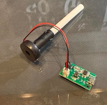
This 5V mist maker also runs off 5V DC. It draws around 0.3-0.5 amps of current and consumes 1.5-2 watts.
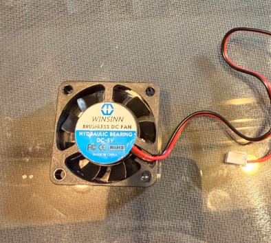
Lastly, this 40mm fan runs off 5V DC. It draws around 0.07-0.15 amps of current and consumes around 0.35-0.75 watts.
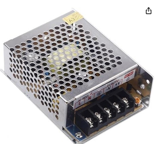
To power everything, I chose to use this PSU. It provides 5V and 30 Watts. This power supply will provide ample power for the project.
System Integration
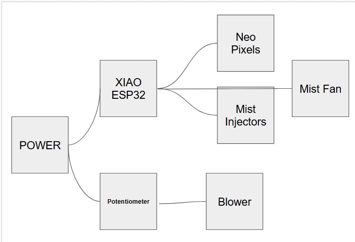
I made this flow chart for my electronics. It shows how power and data are distributed across the system.
(Note I later removed the potentiometer because using a standard potentiometer with a power outlet poses real safety concerns.)
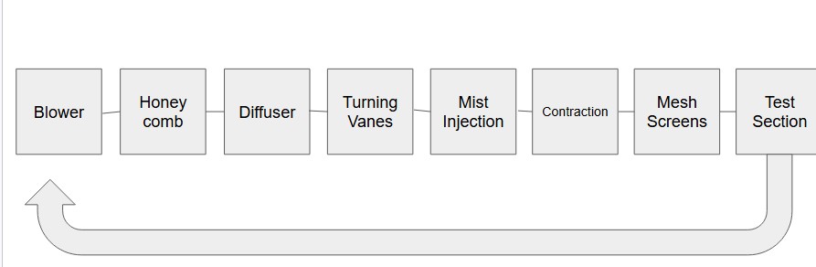
This is the physical flow chart of my wind tunnel. It maps out the loop that the wind goes through.
Applications and Implications, Project Development
What will it do?
This wind tunnel will allow the user to view aerodynamics in real life, without the need of a large wind tunnel.
Who has done it beforehand?
Many people have created small wind tunnels, however most of them have been open loop. Open loop wind tunnels intake air from the outside, then exhaust it. I am creating a closed loop wind tunnel, which not many people have created. I am making my design similar to the Advanced Thermal Solutions, Inc. closed loop wind tunnel. However, my versions will be slightly smaller and more efficient.
What sources will I use?
I have done some research for how to design an efficient wind tunnel. I have looked through many of Nasa's sources on subsonic wind tunnels. Specifically, how to design effective turning vanes in a wind tunnel. To source my parts, I will buy through Amazon or use parts already in the Fab Lab.
What will I design
I will design the entire wind tunnel in Autodesk Fusion. For the electronics, I will design custom PCBs in KiCad.
What materials and components will be used?
For the wind tunnel itself, I will 3d print with PLA. I will mill the PCBs from pcb stock. For mist generation, I will use one of those small 5V mist makers from amazon. For the fan, I will use a blower, for flow visualization, I will use neopixels.
Where will they come from?
All of the components and parts not already in the Fab Lab will be sourced from Amazon.
What parts and systems will be made?
I will need to make a mist injection system for flow visualization. I will also need to design a closed and efficient wind path.
What processes will be used?
I will use 3D printing, PCB milling, and Laser cutting.
What questions need to be answered?
I don't have many questions for the design of the wind tunnel, however im still wondering what will happen to the mist already in the wind tunnel.
How will it be evaluated?
An effective wind tunnel will achieve high wind speed, laminar flow, clear mist flow, and then ease of use.
Invention, Intellectual Property and Income
Dissemination Plan
This project is currently personal, however in the future, I could see this being used by small labs for research. Right now, the project is funded out of pocket. I have purchased all of the components not availible at the lab with my money. Because this project is entirely new, I didn't need to do anything with licensing.
Future Posibilities
As I mentioned earlier, this project could be used by small labs on a budget, or for educational use. This wind tunnel is relatively very affordable and could help bring access to aerodynamic visualization on a budget.
Completed and Remaining Tasks
So far, I have made progress on the mist injection system and CAD design. The wind tunnel has mostly been designed in CAD, however some parts are missing because I have not recieved some parts. The mist injection system is currently being designed. All of the required parts are in, now, CAD design, printing, and assembly are left.
Remaining tasks are finishing the main CAD design, Printing and Laser cutting, and assembly.
Whats Working, Whats Not?
So far, everything has been working perfectly. Before starting the project, I did a long research phase. In this phase, I took plenty of time to figure out exactly what worked, what didn't and what is more efficient. This way, i'm designing with a real purpose in mind.
What Questions Need to be Resolved?
None. I have done all my research and everything has been working as expected.
What Will Happen When?
Prior to June (Research and Planning)
June 1 - June 5 (Finish Mist Injection System)
June 7 (Complete Cad Drawing)
June 8-10 (3D print and lasercutting)
June 11-15 (Assembly)
June 15+ (Testing, Fixing, and Documenting)
Inspiration
I found this closed loop wind tunnel from Advanced Thermal Solutions Inc. to be very interesting. I liked the vertical closed loop design, however I did notice some areas where it could be imporved. I decided to take inspiration and improve off this design for my wind tunnel.
Bill of Materials
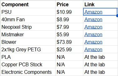
| Component | Price | Link |
|---|---|---|
| PSU | \$10.99 | Amazon |
| 40mm Fan | \$8.99 | Amazon |
| Neopixel Strip | \$7.99 | Amazon |
| Mistmaker | \$5.99 | Amazon |
| Blower | \$73.89 | Amazon |
| 2x1kg Grey PETG | \$25.99 | Amazon |
| PLA | N/A | At the lab |
| Copper PCB Stock | N/A | At the lab |
| Electronic Components | N/A | At the lab |
Above is my bill of materials. I made sure every component is available on Amazon or available at a Fab Lab.
Wiring and Testing Electronics
Here, I setup a breadboard to test my code with the mist maker. Since I had little experience with the NPN transistor, I needed to definitely test before milling my board.
I found a pushbutton and decided to use it to test the mist maker. When the blue light turns on, that means the mist maker board is sending power to the piezo disc, which makes the mist.
You can see when I press the button, the mist maker turns on.
As for the neo pixel, the setup is very easy. Just connect it to power, ground, and a GPIO pin for data.
Electronics Setup:
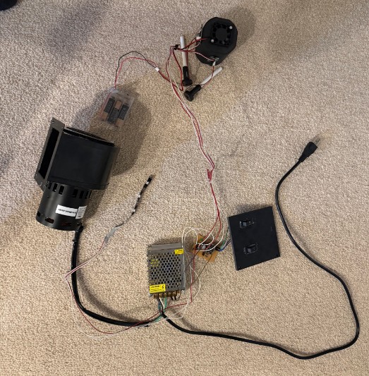
This is my electronics setup. There are a lot of wires but fundamentally, its just connecting a bunch of inputs and outputs to a board. Whats nice is that there is only one power cord. For a while I thought I would need two seperate power cords, one for the blower and one for the PSU. I figured out I could just wire the blower to the AC inputs of the PSU, and the blower would recieve power just like the PSU.
In this video, you can see I wired almost everything with red and white wire. Unfortunately, at the time these were the only two wire colors my lab had, which makes viewing harder. Nonetheless, the circuit still works.
In the video, the XIAO RP2040 was being powered via usb-c from my computer. In the final version of the wind tunnel, I will wire the XIAO directly to the 5V power supply, so only one thing needs to be plugged in on the wind tunnel. In the video, the mist was hard to see, however it was still visible when I moved the camera close to the mist makers. Additionally, the blue power LED was visible, indicating the mist makers were on.
Once I confirmed the electronics were working properly, I hid all the electronics inside the hollow area of the diffuser. Because my diffuser is in the shape of a right triangle inside a rectangle, there will be another right triangle. Since that triangle isn't in use, I decided to use it to store my electronics.
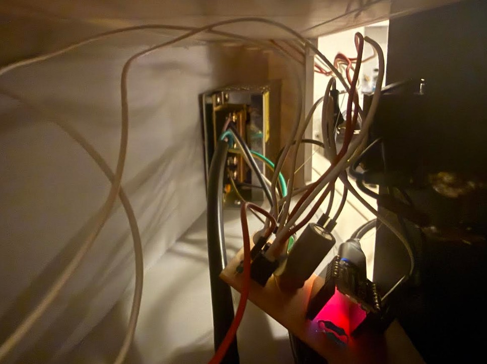
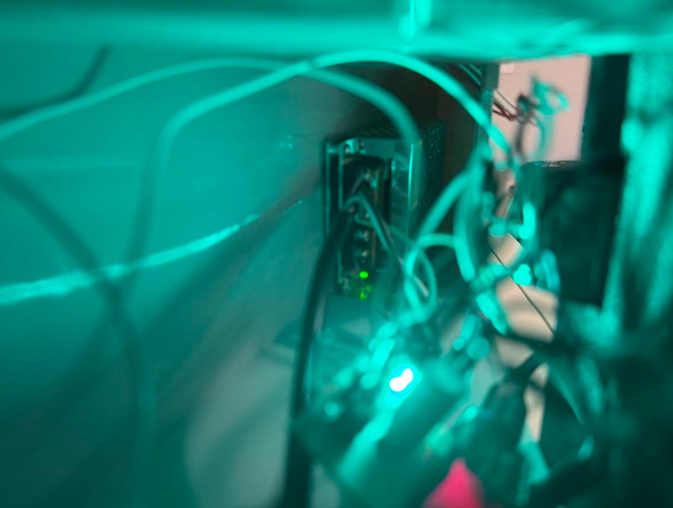
You can see here how I hid the wires. Above is a picture of the hidden electronics with the power off and on.
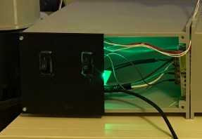
Here you can see how the electronics are integrated into my project. Some wires are still visible however the side cover helps hide the main wiring and PCB. The opening next to the side cover with the buttons allows the user to diagnose power issues. (If something went wrong with the PSU).
Assembly Process
To join the 3d printed pieces together, I used heat set inserts with M3 screws.
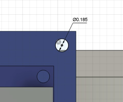
Here you can see for a insert hole in my fusion design, I made the diameter 0.185 inches. This way, the insert could be pressed into the 3d print.
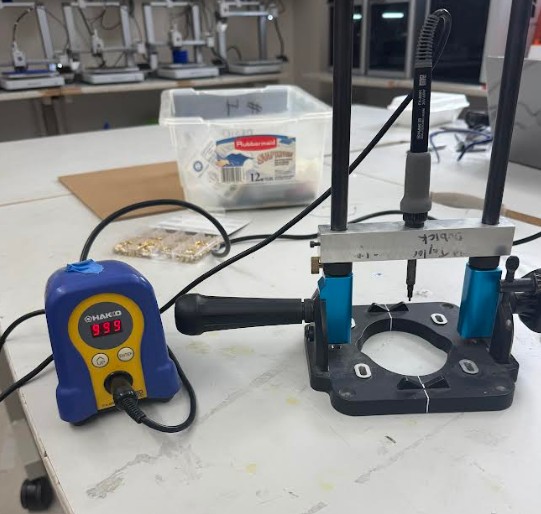
This is the process for inserting heat set inserts into a 3d print: the lab has a dedicated heat set insert soldering iron. I pushed each insert against the holes with the soldering iron until the plastic heated up, softened, then let the insert through. The lab has this dedicated heat set insert soldering iron because using soldering irons to insert heat set inserts can get the tip very dirty and hard to solder with.
This is one of my prints after adding heat set inserts.
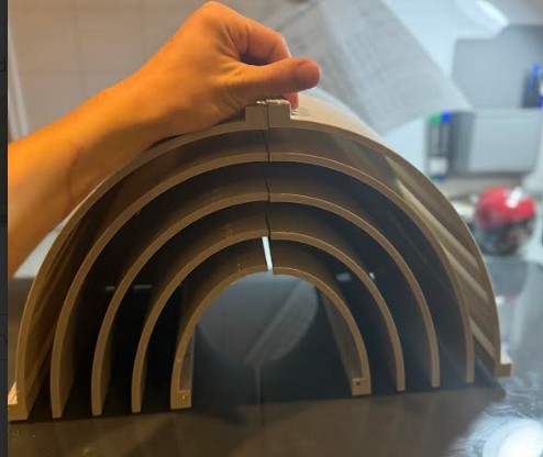
Here you can see the two turning vanes mocked up with eachother.
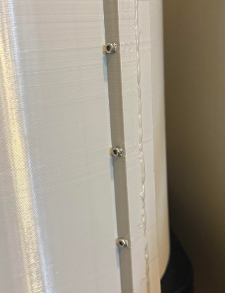
Here you can see how I joined two prints together. One piece has the heat set inserts, and the other piece has hollow holes. A M3 screw can be pushed through one piece, then threaded through the insert in another piece. When the screw is tightened down, it holds the two pieces together.
I also added a hot glue seal along the edge to help keep the wind tunnel air tight.
I used this process of heat set inserts and M3 Screws to join all of my prints together.
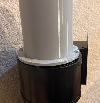
To join the blower to the 3d printed tube, I used the existing screw holes on the blower. I extruded some small holes in the place where the screws go, so I could thread the screw through the print, and into the blower. This way, the tube is held tightly to the blower.
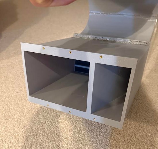
These are some pictures I took during the assembly process. You can see where the wind enters and exits.
Mist Maker
As I mentioned earlier in the CAD section, I designed a mist maker.
This is the mist maker.
This mist maker will blow mist into the hole, and the fan will push the mist into the spout.
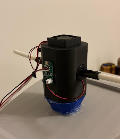
This is the assembled mist maker. I glued the small mist maker driver boards to the print itself.
To use the mist maker, wet the white foam rods coming out of the mist makers.
Here you can see how I attached the mist maker to the wind tunnel.
I used hot glue to seal the edges to make this airtight.
Here, you can see the mist in the wind tunnel.
Final Product
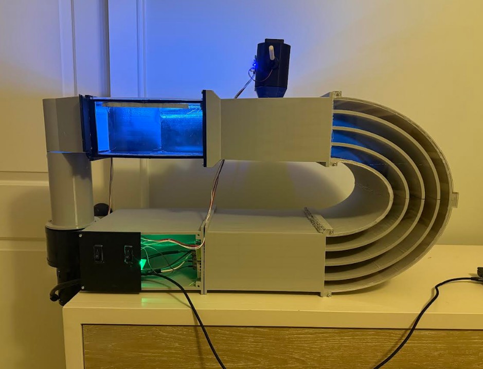
This is the final product. The wind tunnel looks and functions like a final product. The grey design with the blue lighting, and the clean wiring makes the project looks even better.
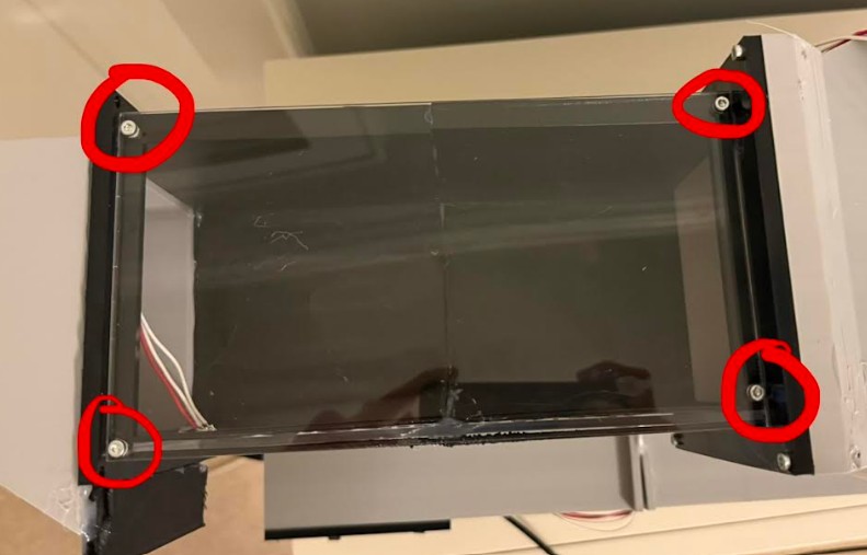
These four holes allow the top window to be removed. This way, the user can place an object in the wind tunnel without needing to disassemble components.
In this video, you can see the blower, neopixels, and mist maker functioning.
Project Reflection
After finishing this project, I feel super relieved. Because of exams, I didn't have much time to finish this project before the presentation. I worked super hard and late into the nights because I was behind. I still managed to finish this project before the presentation. The night before the presentation, I went to bed super late. When it came time for my presentation, Dr. Gershenfeld asked me some questions about my project like "Is there a diffuser?". My brain blanked and I said no, but then later realized I did have a diffuser. I still feel very proud of my project. In the future, I plan to keep refining the mist system. In the videos, it is hard to see. I also liked Dr. Gershenfeld's suggestion of a loadcell. This way I can use my wind tunnel to measure lift and downforce.
CAD DESIGN FILES
Click Here to download a zipped folder with all 2D CAD Files
Click Here to download a zipped folder with all 3D CAD Files
Original Fusion Files:
Click Here to Download the Wind Tunnel Fusion File
(This file contains the 3d CAD models as bodies, and the 2D CAD models as sketches.)
Click Here to Download the Mist Injector Fusion File
Discontinued Designs
Below are old designs for this project. They were part of an open loop wind tunnel idea. I decided not to use an open loop wind tunnel because they are less efficient compared to a closed loop wind tunnel.
Wind Tunnel Design V1 (Discontinued)
In the field of engineering, one of the most crucial aspects is aerodynamics. The problem is, we cannot see air. The only way to visualize aerodynamics is with either a multi million dollar industrial scale wind tunnel or a digital aerodynamics simulation. For my project, I wanted to make a way for the average person to be able to view air interacting with objects, not in a digital simulation.
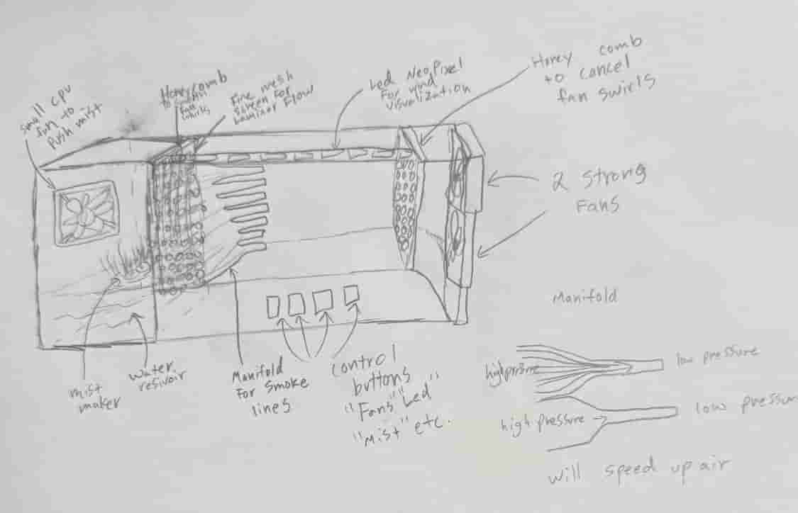
I drew this picture which shows my full wind tunnel and the different components.
I would use mistmakers to generate the visual wind and a neo pixel to make the wind even more visible. A small intake fan would be used just to push the mist forward but the main flow would come from the two rear fans. Honeycombs would be used to cancel out the swirls generated by the fans, and a mesh would be used to create laminar flow.
An Intake manifold using a high to low pressure zone would create nice wind lines like the ones seen in many wind tunnels. The high to low pressure zone would also help keep laminar flow and speed up the wind.
I would have buttons at the bottom to control things like LEDs, fans, mist makers, etc.
If possible, I would like to add a mechanism that opens the test chamber using a stepper motor or servo.
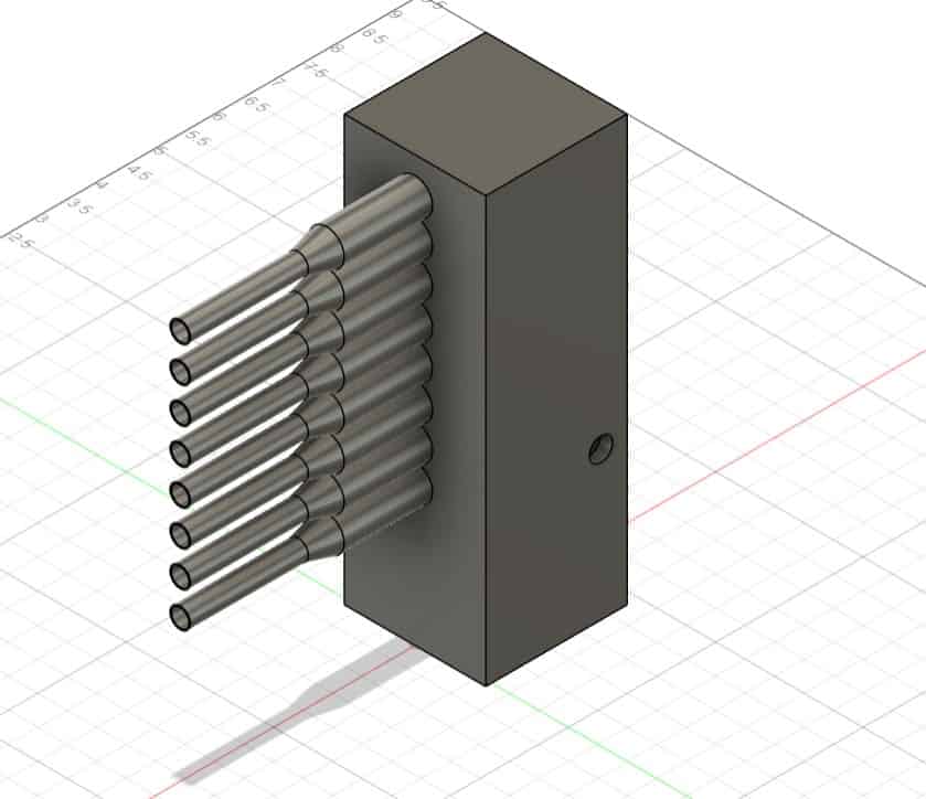
Mistmaker-V1 (Discontinued)
This week I was tasked with using a CAD software to design something in my final project.
I choose to model the wind tunnel's manifold because it is a complex part requiring many different features that Fusion offers.
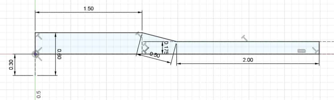
I started off with a 2d sketch. I wanted to revolve a profile around an axis. I sketched a line to revolve around and then created the profile I wanted to revolve.
I finished the sketch and used the revolve feature to create a single 3D manifold.
I used the shell feature to hollow out the inside so air can travel through.
I copy and pasted the manifold 8 times and placed each one on top of eachother. The total height is approximately 6 inches.
I added a base for this mistmaker so that the mist it produces gets fed into the manifold.
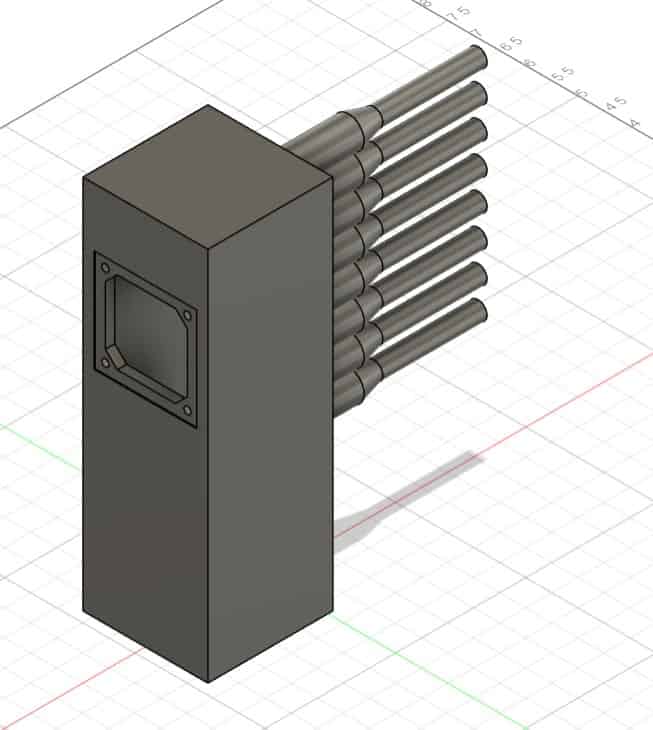
This is the complete manifold. Additionally, I added a space for a fan to be connected to help push the mist into the manifold and to make sure that it doesn't become a low pressure zone. I found a diagram of a 50mm fan here. The hole on the side is for the wires from the mist maker to come out of.