Week 16 System Integration
Wind Tunnel - Electronics Flow Chart
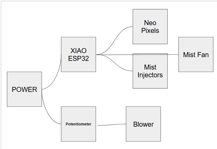
This is my electronics flow chart. Because my blower requires a significant amount of power, (More than the maximum of 5V the Xiao ESP32 can output) I decided to run the blower straight from an outlet. I will use a potentiometer on the ground wire to control the blower speed. As for the ESP32, it will run off a small 5V power supply, also powering neopixels (for flow visualization) and mist injectors (also for flow visualization).
Wind Tunnel - Physical Flow Chart
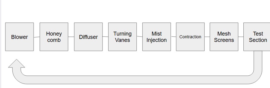
This closed loop flow chart ensures efficient wind movement and laminar flow where necessary. The flow chart is similar to the Advanced Thermal Solutions, Inc. Wind tunnel design. The design keeps many of the same features, but improves on the design, like adding turning vanes and a more gradual diffuser. I also added flow visualization, something that the ATS wind tunnel lacks.
Physical Design
At this point, I have not finished modeling my wind tunnel, however I do have the general insperation model.
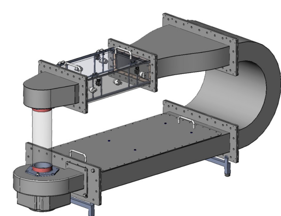
As I mentioned earlier, this is the Advanced Thermal Solutions, Inc. Wind tunnel. I believe this wind tunnel's vertical is more convenient than the traditional flat layout because of it takes up less ground space. The wind tunnel will need to use slightly more energy than a flat design because the vertical design must move wind up, fighting gravity. While this wind tunnel's vertical design does make it great, it lacks many feautres that decrease it's overall efficiency. For example, when the airflow changes direction on the U shaped piece, the centrifugal force of the wind turning creates a higher pressure by the outside wall, and a lower pressure on the inside turning wall. When the airflow straightens out again, and the centrifugal force is gone, the wind turns over on itself to reach the lower pressure area. This creates a wave of wind, compared to a straight flow. By adding turning vanes, the wind tunnel can achieve lower a more distribution of pressure through the wind tunnel. Additionally, this inspiration does not feature an appropriate diffuser. The wind rapidly enters a larger chamber, at a 90 degree angle. My model will feature a gradual diffuser through the long space below the test chamer and contraction.
Packaging Electronics/Wires
When electronics and wires are exposed everywhere on a project, it makes it look incomplete. In the original design, there is a straight rectangular shape below. I will keep that shape, but since I have a diffuser, There will be a hollow triangular shape. In that place, I will store my electronics and wires.
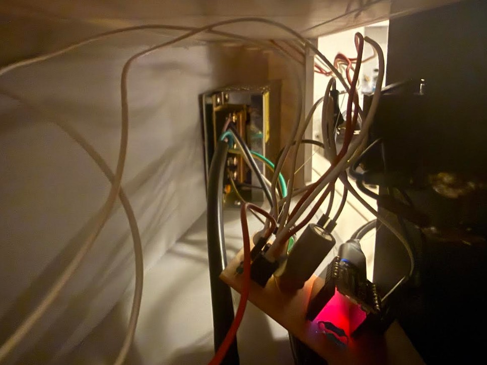
Here, you can see how I hid the wires and electronics.
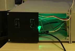
Here, you can see where the wires are hidden in my project.
Cable Positioning
The cables will mainly run down the wind tunnel and towards the control board.
Designing to Look Like a Finished Product
For larger sections, I plan to lasercut with acrylic. This way, I won't have to join large 3d prints together. For the intricate components, I plan on 3d printing.
Connected parts
Input Devices
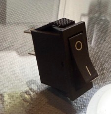
For the input device, I chose to use this generic 2 pin toggle switch. The 2 pin design makes it very easy to incorporate onto a circuit.
I used 2 of these switches.
I connected 1 end to a GPIO pin, and the other to GND. This way, the RP2040 can detect when the button has been pressed.
Output Devices
Compared to the simple input device for this project, the output devices are more complicated.
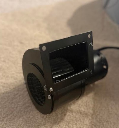
The blower above runs of American AC (120V AC 60HZ). It draws around 0.75-1.5 Amps. It consumes around 85-175 Watts of power. It produces 115-145 CFM of airflow, and it spins at over 3000 RPM.
This blower does consume a lot of power, however since I will be running it straight from a power outlet and not a PSU, power management is not a concern for this component.
![]()
This neopixel strip above, with about 6 actual neopixels on the strip runs on 5V DC. The neopixel draws only around 0.12 amps and consumes around 0.6 watts.
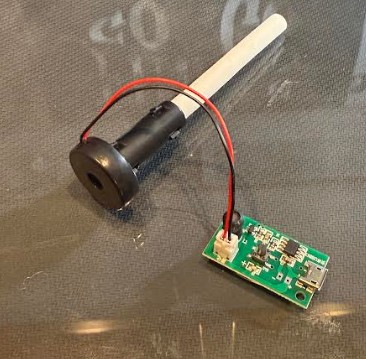
This 5V mist maker also runs off 5V DC. It draws around 0.3-0.5 amps of current and consumes 1.5-2 watts.
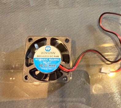
Lastly, this 40mm fan runs off 5V DC. It draws around 0.07-0.15 amps of current and consumes around 0.35-0.75 watts.
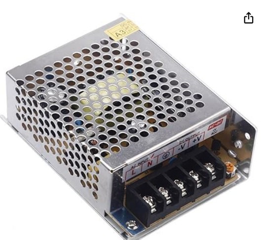
To power everything, I chose to use this PSU. It provides 5V and 30 Watts. This power supply will provide ample power for the project.
STL FILES
**Click here to download a folder containing all of my stl files