Week 9 Input Devices
This week, I decided to use a potentiometer. A potentiometer is a variable resistor that can be controlled by hand, making it a very useful device to allow users to input a analog range of inputs.
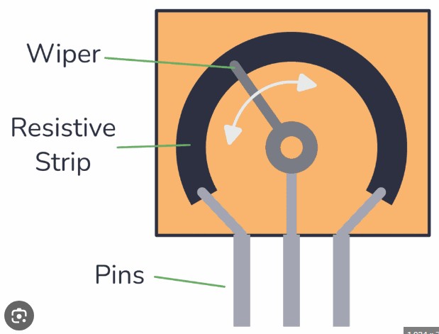
This image shows how a potentiometer works. Ohms law states that resistance is directly proportional with the distance of material that the current has to pass through. Depending on the location of the middle pin, or the wiper, on the resistive strip determines the resistance. By attatching that pin to an input pin of a microcontroller, you can read the voltage because a potentiometer acts as a voltage divider.
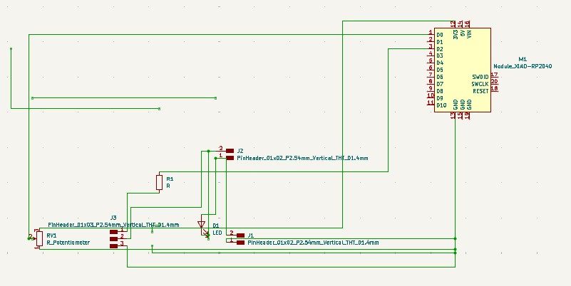
I created this schematic in Kicad. I decided to use a motor to visualize the varying input values. The 3 pin connector is a mosfet. I couldn't find a footprint for the specific mosfet I decided to use so I went with a 3 pin connector because it creates three through holes. One of the two pin connectors connects a battery pack to the circuit because the motor needs 6V, and the other connects the DC motor to the circuit. I added a flyback diode to protect my microcontroller from back EMF.
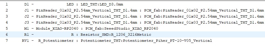
These are the footprints I used. The LED footprint is for the diode.
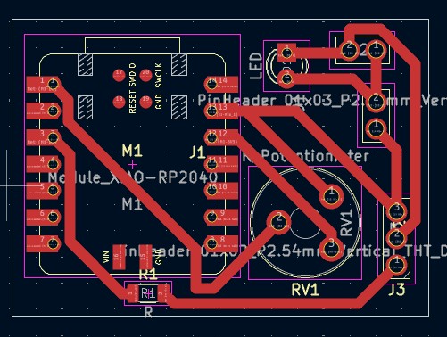
I imported all of the footprints into the pcb editor, arranged them, then sketched the traces. I gave my board larger traces because in the past, some of my traces ripped away during the soldering process. I made my board compact to save on material cost.
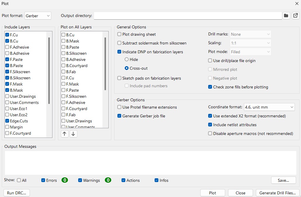
After I designed my board, I went to file, fabrication outputs, then gerbers. These are the settings I used to generate my gerbers. I only needed the front copper gerbers and the edge cut gerbers, but ended up generating gerbers for more because I forgot to uncheck those boxes. Gerbers only generate the traces, so I needed to generate the drill files for the through holes.
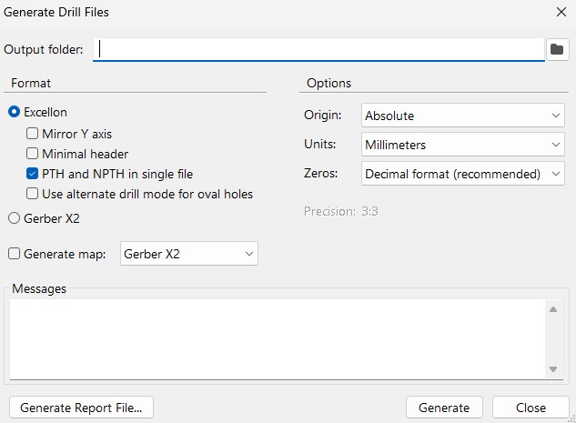
I went to the same place to generate the drill files. File, fabrication outputs, then drill files. These are the settings I used to generate the drill files.
**Click Here to download my KiCad file
(The Gerbers are in the KiCad file, the .drl file is not)
**Click Here to download the .drl file
Makera Cam Settings
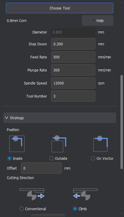
I used these settings above in Makera CAM for my traces. This toolpath goes with the traces gerbers.
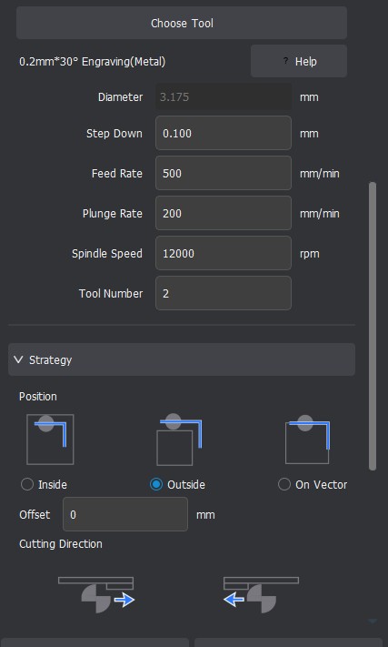
I used these settings above in Makera CAM for my outline. This toolpath goes with the outline gerbers.
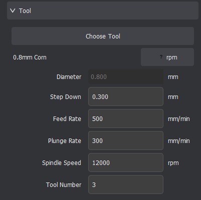
I used these settings in Makera CAM for my through holes. This toolpath goes with the .drl file.
After I created the toolpaths, I generated the gcode.
Click Here to Download the GCode
Milling, Soldering, and Populating the Board
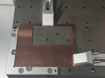
I put this copper stock on the bed, with double sided tape under it, then finally clamped it down.
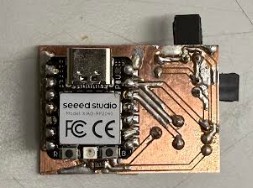
This is my board after milling, soldering, and populating. As you can see, I had a hard time soldering. I did make sure I didn't have any solder bridges.
Code
I asked ChatGPT to generate my code. It came back with:
from machine import Pin, ADC, PWM
import time

# Potentiometer on A0 (GPIO 26)
pot = ADC(Pin(26))

# TIP120 base driven from D2 (GPIO 28)
motor = PWM(Pin(28))
motor.freq(2000)  # TIP120 works better at higher PWM frequency

while True:
    val = pot.read_u16()
    motor.duty_u16(val)
    time.sleep(0.01)
Code description
This code reads the position of a potentiometer using the RP2040’s ADC and gets a value between 0 and 65535. It then uses that value to set the PWM duty cycle on a pin driving the TIP120, so the motor speed changes smoothly as you turn the knob.
Testing
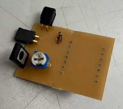
After my first test, my diode started smoking.
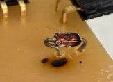
As you can see, part of the board was burned, but it still worked. I decided to desolder the diode. My board doesn't require a diode to work. The diode just long term protects my microcontroller from the back EMFs emitted from the dc motor. Once I took the diode off, the board worked properly.
This is my video working. As you can see and hear, when I turn the potentiometer, the motor's speed increases and decreases. I had to use a small flathead screwdriver to turn the potentiometer because its very small.
Here is another video of my board working, but with another motor where the rotation is more visible.
Serial Monitor Value
Later, I updated the code with a print(val) line, which makes the serial monitor print out the potentiometer value.
from machine import Pin, ADC, PWM
import time

# Potentiometer on A0 (GPIO 26)
pot = ADC(Pin(26))

# TIP120 base driven from D2 (GPIO 28)
motor = PWM(Pin(28))
motor.freq(2000)

while True:
    val = pot.read_u16()

    motor.duty_u16(val)

    print(val)   # <-- THIS is what shows up in Serial Monitor

    time.sleep(0.01)
Above is the updated code.
Testing
I actually tested the same potentiometer by itself. The potentiometer on the board was outputting very jittery values that were hard to read. Despite the Jittery values, the board still functions. However for testing the potentiometer value, using a external potentiometer was easier.
Reflection
This week still got pushed back a bit from my spring break. My board started smoking which was very scary. Luckily, I was still able to get my board working. The group project also got pushed back, but we eventually got it done. Overall, this week wasn't too difficult, spring break and easter break still messed up the timing of everything.
Link to Group Project