Week 11 Networking and Communications
This week, I had to make two microcontrollers communicate wirelessly. I chose the Xiao ESP32C3 because these microcontroller are very easy to network.
Communication System
The two Xiao ESP32C3 microcontrollers will communicate with eachother via ESP-NOW.
ESP-NOW bypasses the need for a traditional Wi-Fi router by using the MAC addresses of the boards to communicate directly peer-to-peer. It transmits small payloads (up to 250 bytes) instantly, making it highly efficient.
Board
I wanted to create a new board this week, housing two different circuits that are not connected physically. I wanted one board to have an input, and the other to have an output. For the input device, I chose a pushbutton, and for the output, I chose an LED.
Resistor Choice
For the LED, I chose not to use a resistor. The esp32c3 GPIO pins output 3.3V. My pure green LED, made of InGaN operates around 3-3.2V. using 3.3V through the will not cause much harm. Long term, adding an LED would make more sense. However, for short term testing, not using a resistor was easier because it is one less component to worry about.
I read this article to learn about the ESP32C3
For the pushbutton, I also didn't need to use an external resistor because I can utilize the ESP32's internal pull up resistor. If the ESP32 did not have the internal pull up feature, I would need an external resistor.
Board Design
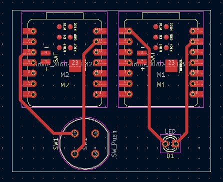
I created this simple board in Kicad. As you can see, the two microcontrollers and their input/output device are not connected to the other microcontroller.
Gerber and Drill Files
Click Here to download the Edge Cut Gerbers
Click Here to download the Front Copper Gerbers
Click Here to download the Drill Holes
Milling
I used the Carvera Milling Machine, the same machine I have used to mill all my other boards. For the front copper traces, I used a 0.3mm bit. For the Edge Cuts and Drill Holes, I used a 0.8mm Corn Bit.
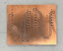
As you can see, some of the traces are cut very well, and the others are not. On the first milling job, I set the traces depth to 0.1mm. Some of the traces didn't cut all the way through. After that, I made a toolpath that only milled the important traces to save time. This time, I set the trace depth to 0.2mm. As you can see, it worked well.
Soldering and Populating
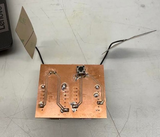
This is the board after soldering and populating. Overall, my soldering wasn't to bad. For the header pins connecting the ESP32s to the board, I only soldered the necessary connection points and some other points for stability. I did this because not all the pads milled out properly like I mentioned before and it is hard to solder without pads.
Board Setup and Coding
Because I was new to this process, I used ChatGPT to help me. First, it told me I needed to find the MAC address of the reciever board (The board with the LED attached to it). To do this, I plugged in the ESP32 into my computer and uploaded this code to it in Arduino IDE.
My Prompt:
Hey ChatGPT, I am a Fab Academy student and I need help with Networking and Communications. I have two esp32c3 board. I want them to use ESP-NOW to communicate. One has a pushbutton connected from D2 to GND. The other esp32c3 has an LED connected to D0. I want the LED to light up when the pushbutton is pressed. Can you help me with this?
Click Here to download ChatGPT's response
#include <WiFi.h>

void setup() {
  Serial.begin(115200);
  WiFi.mode(WIFI_STA);
  Serial.println(WiFi.macAddress());
}

void loop() {}
The job of this simple code is to find the MAC address in the serial monitor.
After uploading, the board responded with it's MAC Address in the Serial Monitor.
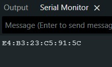
This is what it looked like.
Now that I had to MAC Address, ChatGPT told me to upload this code to the Sender ESP32.
#include <WiFi.h>
#include <esp_now.h>

#define BUTTON_PIN 4

uint8_t receiverMAC[] = {0xE4, 0xB3, 0x23, 0xC5, 0x91, 0x5C};

typedef struct {
  bool buttonState;
} Message;

Message msg;

void setup() {
  Serial.begin(115200);
  pinMode(BUTTON_PIN, INPUT_PULLUP);

  WiFi.mode(WIFI_STA);

  if (esp_now_init() != ESP_OK) {
    Serial.println("ESP-NOW init failed");
    return;
  }

  esp_now_peer_info_t peerInfo = {};
  memcpy(peerInfo.peer_addr, receiverMAC, 6);
  peerInfo.channel = 0;
  peerInfo.encrypt = false;

  esp_now_add_peer(&peerInfo);
}

void loop() {
  msg.buttonState = (digitalRead(BUTTON_PIN) == LOW);
  esp_now_send(receiverMAC, (uint8_t *)&msg, sizeof(msg));
  delay(100);
}
This is an ESP-NOW transmitter for an ESP32. It reads a button and continuously sends its state (pressed / not pressed) to another ESP32 using low-power WiFi peer-to-peer communication.
As you can see, the code contains the MAC address of the reciever ESP32.
I also had to code the reciever board. ChatGPT told me to use this code.
#include <WiFi.h>
#include <esp_now.h>

#define LED_PIN 2

typedef struct {
  bool buttonState;
} Message;

Message msg;

void onReceive(const uint8_t * mac, const uint8_t *incomingData, int len) {
  memcpy(&msg, incomingData, sizeof(msg));
  digitalWrite(LED_PIN, msg.buttonState ? HIGH : LOW);
}

void setup() {
  Serial.begin(115200);
  pinMode(LED_PIN, OUTPUT);

  WiFi.mode(WIFI_STA);

  if (esp_now_init() != ESP_OK) {
    Serial.println("ESP-NOW init failed");
    return;
  }

  esp_now_register_recv_cb(onReceive);
}

void loop() {}
This code sets up an ESP32 to receive wireless ESP-NOW messages from another device. When a message arrives, it reads a button state value from the data and immediately turns an LED on GPIO 2 on or off to match it. The loop is empty because everything happens automatically through the receive callback.
Reciever Code Description:
The receiver Seeed Studio XIAO ESP32C3 listens for incoming ESP-NOW messages and turns an LED on GPIO2 on or off depending on whether it receives a “pressed” or “not pressed” signal from the sender.
Sender Code Description:
The sender Seeed Studio XIAO ESP32C3 reads a pushbutton on GPIO4 and continuously sends its state (pressed or not pressed) wirelessly using ESP-NOW to a specific receiver identified by its MAC address.
Testing
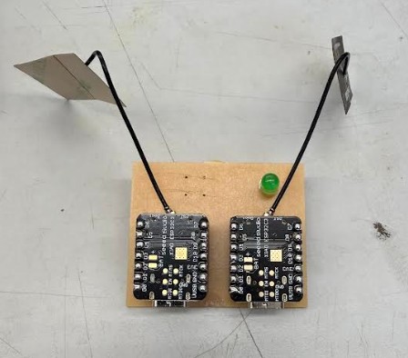
As you can see when I press the button, The LED lights up. The code works!
Reflection
I put this week off for a long time. Infact, I completed this week during week 14. I thought this week would be a very difficult week, since I was new to networking. However, I ended up completing the individual assignment in a single day.