Final Project
Final Project Development Timeline
This section documents how my final project developed over the FabAcademy weeks. Instead of showing only the final result, I want to show the technical path behind it: first ideas, early prototypes, electronics, communication, interaction, system planning, and final integration.
Week 20 - Final Project
June 3, 2026
This week was about completing, documenting, and presenting the fully integrated final project. The goal was to bring all separate parts together and demonstrate the knowledge and skills developed throughout the FabAcademy.
I produced the final PCBs for the sender and receiver unit, assembled the electronics, and soldered the components. For the receiver unit, I prepared the board that controls the WS2812B LED strip inside the lamp. For the sender unit, I worked on the electronics for the contactless control interface with the Time-of-Flight sensors and button input.
A large part of this week was also focused on the physical build. I cast the silicone diffuser, finished the wooden lamp body and lamp base, and integrated the LED strip, wiring, electronics, and covers into the final object. I also completed the sender unit as a separate control device and worked on the final system integration between sender, receiver, lamp body, and software.
The final coding connected the different parts of the project and made the lamp usable as a complete system. At the end of the week I prepared the final presentation material, including the slide and video, to explain the concept, construction, function, and development process of the project.
Read the full Week 20 documentation
Week 19 - Invention, Intellectual Property & Project Development
May 27, 2026
This week’s goal was to complete and document the final project, develop a dissemination plan, track the current progress, evaluate remaining challenges, and reflect on the overall development process and lessons learned.
I worked on the dissemination plan for the project and thought about how the lamp could be shared, presented, and developed further after FabAcademy. This included questions about license, use, intellectual property, possible income models, and future development. I also reflected on which parts of the project should stay open and reproducible, and which parts could maybe become more refined in a later version.
Another important part of this week was the project status review. I documented the completed tasks, the remaining tasks, what was already working, and what was not working yet. This helped me to clearly see the current direction of the project and to define the most important open technical questions before the final presentation.
I also created a timeline for the remaining days until the final presentation and thought about a possible Version 2 after FabAcademy. This week was important because it connected the technical work with a more strategic view: what the project is now, what it could become, and what I learned from developing it.
Read the full Week 19 documentation
Week 18 - Applications & Implications, Project Development
May 20, 2026
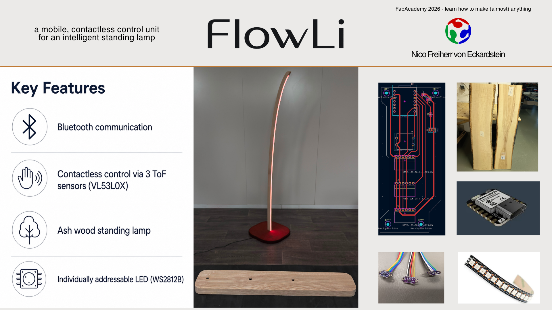
In this week I clarified the function, scope, materials, components, and open questions of my final project. The project was defined as a contactless controllable floor lamp consisting of two units: a sender unit for user input and a receiver unit as the actual lamp.
The sender uses three VL53L0X Time-of-Flight sensors to read the distance of my hand. These values are used to control RGB color values or other light modes. A button confirms the selected value and sends it to the lamp via BLE.
The receiver controls a WS2812B LED strip with FastLED. The LEDs are integrated into the wooden lamp body and covered by a self-made silicone diffuser. This week helped me to bring the previous technical tests into one clear final project plan and to define the remaining questions for sensors, interaction, communication, power, mechanics, and design.
Read the full Week 18 documentation
Week 16 - System Integration
May 6, 2026
This week was about bringing the separate parts of my project together as one complete system. Before this point, I had tested several parts separately: ToF sensors, LED control, wireless communication, input handling, and the general lamp geometry.
The main focus was to define the complete system architecture. The final project is not only one object, but two connected products: a sender unit for interaction and a receiver unit as the lamp. The sender reads the user input with three Time-of-Flight sensors, while the receiver controls the light output of the WS2812B LED strip.
I also worked on the mechanical and electronic integration. The sender should become a clean table unit with protected sensor openings, microscope slide glass covers, internal electronics, and serviceable screw connections. The lamp itself should hide the electronics inside the base, route the cables cleanly, and integrate the LED strip and diffuser into the wooden body.
I also determined the final lamp shape.
Read the full Week 16 documentation
Week 15 - Interface & Application Programming
April 29, 2026
In Week 15 I built a simple mobile interface for my ToF sensor board. The goal was not to create a visually complex app, but to make the sensor data visible and easy to understand.
I used MIT App Inventor to create a basic app that connects to my ESP32-C3 based ToF board via Bluetooth Low Energy. The board sends the three measured distance values as a compact data string, and the app receives, splits, and displays them as separate live sensor values.
This was an important step for the final project, because it proved that the sensor data can be transferred wirelessly and shown on a user interface. Even if the final lamp interaction does not need a phone app as the main control method, this test helped me understand the BLE data flow between hardware, firmware, and interface.
Read the full Week 15 documentation
Week 13 - Midterm Review
April 15, 2026
For the Midterm Review I created a system diagram and a Gantt chart for my final project. This was the first larger planning step where I organized the remaining tasks, the required subsystems, and the overall project structure.
The system diagram helped me to separate the project into input, processing, communication, output, power, and mechanical parts. The Gantt chart helped me to understand how much time was still available and which parts had to be finished first.
This week was less about building a physical prototype and more about making the project manageable. It gave me a clearer overview of the remaining work and helped me prepare the development path towards final integration.
Read the full Week 13 documentation
Week 11 - Networking & Communications
April 1, 2026
In this week I connected two of my previous boards wirelessly. I used the dev board from Electronics Production together with the ToF sensor board from Input Devices and tested communication between them.
For this first communication test I used WiFi / ESP-NOW between two ESP32-C3 Superminis. The sender board read the ToF sensor values, mapped the distance range to values between 0 and 255, and transmitted the values to the receiver board.
This was an important proof of concept for my final project, because the final lamp is based on the idea of separating the interaction unit from the lamp body. The sender can be placed on a table, while the lamp remains somewhere else in the room. This makes the interaction more flexible and keeps the visible lamp design cleaner.
Read the full Week 11 documentation
Week 10 - Output Devices
March 25, 2026
In Week 10 I focused on the output side of my final project. Since my final project is a floor lamp, the WS2812B LED strip is one of the most important components.
I tested a full-length LED strip with my own board and an external power supply. This was necessary because the LED strip requires significantly more current than a microcontroller can provide directly. The test helped me understand the power requirements, wiring, data signal connection, and general behaviour of the LEDs.
The first code controlled the full LED strip and changed the displayed color. This was the first time the output side of the final lamp was tested on a more realistic scale.
Read the full Week 10 documentation
Week 9 - Input Devices
March 18, 2026
In Week 9 I produced and assembled the first ToF sensor PCB. The board was based on the electronics design from Week 6, but I adjusted the design before milling and added a button to make the board more useful for later interaction tests.
After milling the PCB, I tinned the copper surface, soldered the components, and checked the board with a multimeter. There was some minor rework, but after that the board had no short circuits and the traces were correctly connected.
I then uploaded a first test program for the VL53L0X sensor. This made the board a real input prototype for my final project, because I could start reading distance values and use them as the basis for contactless interaction.
Read the full Week 9 documentation
Week 7 - Computer-Controlled Machining
March 4, 2026
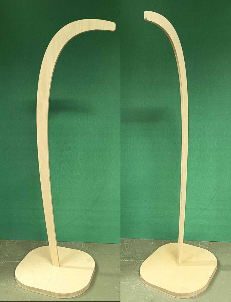
In Week 7 I milled the first larger physical prototype of my lamp. The goal was not to build the final object yet, but to check the proportions, scale, and basic stability of the design in real material.
I used the CNC machine to produce a simplified version of the lamp from multiplex wood. This helped me move from a digital CAD idea to a real object and gave me a much better feeling for the size and shape of the final lamp.
The prototype also showed which parts of the geometry still need attention before the final version. Especially the connection between the vertical lamp body and the base is important, because the final lamp has to stand safely and still look clean.
Read the full Week 7 documentation
Week 6 - Electronics Design
February 25, 2026
In Week 6 I designed the first PCB for the input side of my final project. The board was based on an ESP32-C3 Supermini and three VL53L0X Time-of-Flight sensors.
The main goal was to understand the electronics architecture instead of only connecting components. I used the I²C bus for the sensors and added separate XSHUT lines, because all VL53L0X sensors have the same default I²C address. With individual XSHUT control, the sensors can be initialized one after another and assigned different addresses.
This was an important technical step for the final project. It created the base for the later contactless RGB interaction, where each sensor can represent one colour channel.
Read the full Week 6 documentation
Week 4 - Embedded Programming
February 11, 2026
In Week 4 I built the first small lamp prototype with WS2812B LEDs. I used a short LED strip and programmed it myself with FastLED.
The prototype was still very small, but it was the first physical test of the basic lamp idea. I tested RGB control, LED addressing, different input options, and the general behaviour of the LED strip. This made the project more tangible, because the lamp concept was no longer only a CAD idea.
I attached the LED strip to a small prototype body and routed the cables through a notch. This simple test helped me understand how the electronics, code, and physical lamp shape could later come together.
Read the full Week 4 documentation
Week 2 - Computer-Aided Design
January 28, 2026
Week 2 was the first real design step for my final project. I used Autodesk Fusion to create a first 3D model of the lamp and to get a better feeling for the proportions, height, base, and overall shape.
At this stage the design was still a concept, but many important decisions started here. I already thought about the visual direction, possible material combinations, wall thickness, internal space for electronics, and the stability of the lamp. Even though I tested different appearances in the rendering environment, ash wood became my favourite material very early.
The rendering helped me evaluate the lamp not only as a technical object, but also as a visible product in a room. This early CAD model became the starting point for the later prototypes, CNC tests, and the final product direction.
Read the full Week 2 documentation
Week 1 - Project Management
January 28, 2026
For my Final Project I began to think about something that I would like to contruct based on intrinsic motivation and that would provide me with real added value.
So I decided to design a floor lamp with a custom control system.
This project focuses on mechanical design and the combination of various manufacturing technologies, connected to an external contactless control unit.
floor lamp
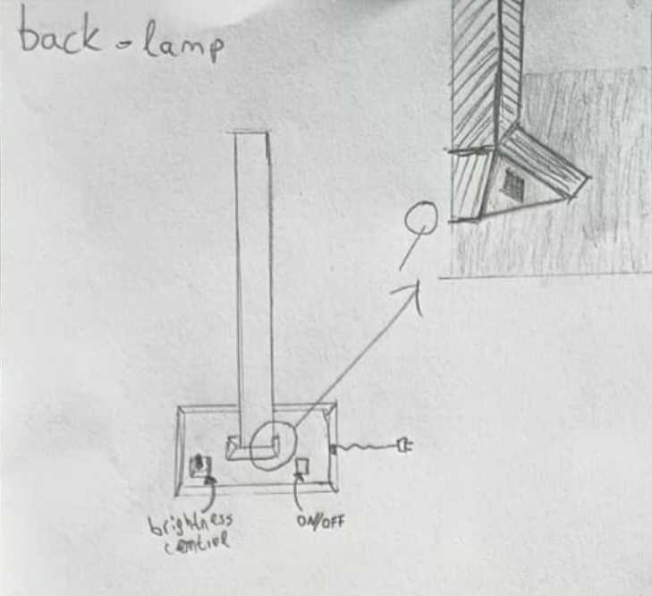
The base of the lamp incorporates a brightness control and other electronic components.
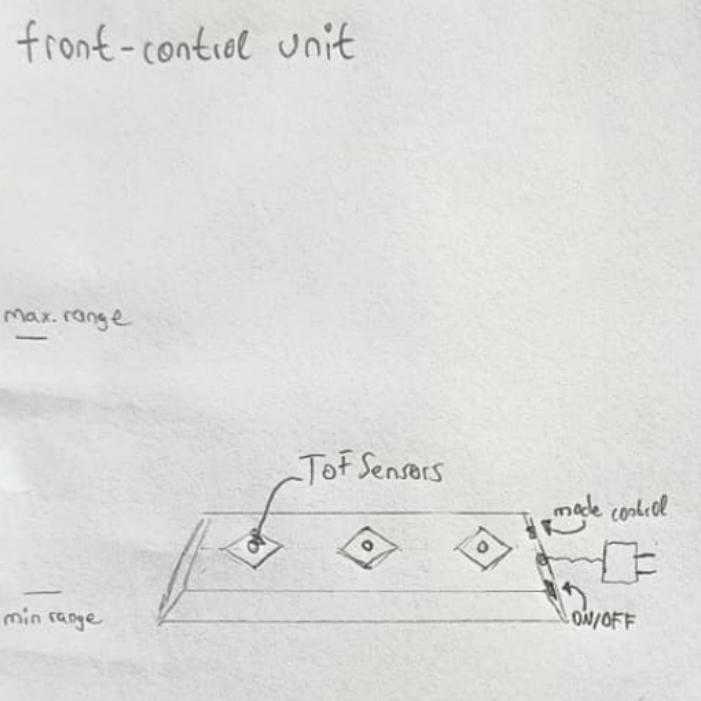
control unit
The control unit can control the colors of the lamp via 3 Time of Flight Sensors. In addition to static adjustments, various modes allow the user to set dynamic programs that can be changed and anable playful interaction.
Its infrared (Time of flight) sensors and the mode control are connected with the components for controlling and communication with the lamp. A stylish case incorparates all the components.
The bill of materials is minimized nevertheless expansion is possible.
Use case
Wether you simply want to change the ambiance of the lighting on a quiet evening, or want to add more expression to your dancing on a fun dance night throught the unique interaction with gesture contol via the control unit, this system makes it all possible.
Here is a small sketch to help you imagine it better.
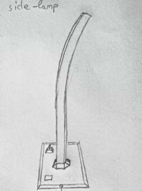
Read the full Week 1 documentation