Networking & Communications
This week’s goal was to design, build, and connect networked nodes with local input/output devices and enable communication between two projects.
Watch our progess at the Group Page
Introduction
Communication between microcontrollers is an essential part of embedded systems design.
It makes it possible to connect separate boards, distribute tasks, exchange sensor data, and build modular systems instead of isolated devices.
Depending on the application, data can either be transmitted through wires or wirelessly. Both approaches have advantages and limitations in terms of reliability, complexity, speed, range, and energy consumption.
A common wired communication method is UART (Universal Asynchronous Receiver Transmitter). UART is simple and widely used for direct serial communication between two devices.
It only requires a transmit and a receive line, which makes it easy to implement, especially for debugging and point-to-point communication. However, it is less suitable when multiple devices need to share the same bus.
Another widely used protocol is I²C (Inter-Integrated Circuit). I²C uses only two lines, one for data and one for clock, and allows multiple devices to communicate on the same bus by using addresses.
This makes it very efficient for connecting sensors, displays, or other peripherals on a single board or between closely connected boards.
Its main limitation is that it is intended for short-distance communication.
SPI (Serial Peripheral Interface) is another wired communication standard. It is usually faster than I²C and is often used when higher data rates are required.
SPI uses separate lines for clock, data in, data out, and chip select.
This makes it very reliable and fast, but also increases wiring complexity, especially when multiple devices are connected.
For longer distances or more robust industrial applications, protocols such as CAN or RS-485 can also be used.
These systems are designed to be more resistant to noise and are often found in automotive, industrial, or machine-related environments.
For my project, however, these protocols would have been unnecessarily complex.
Besides wired communication, microcontrollers can also exchange data wirelessly. One common option is Bluetooth, which is suitable for short-range communication and low-power applications. It is often used when mobile devices such as smartphones are involved.
Another common option is Wi-Fi, which enables wireless communication over a greater range and allows higher data throughput.
This makes it very useful when devices should communicate without cables and without being physically close to each other.
Other technologies such as LoRa or Zigbee are also relevant in certain use cases, especially when low power consumption or long range is more important than transmission speed.
Wireless communication is especially interesting when thinking about energy-aware manufacturing. Avoiding cables can reduce material usage and simplify system integration, but wireless systems also require active communication hardware and consume more power during transmission (0,5-3W+ for Wi-Fi). This means that the most sustainable solution depends on the actual application. In some cases, wired systems are more energy-efficient and robust. In other cases, wireless communication reduces material complexity and enables more flexible designs. For this week, this aspect played a small role in my decision-making process.
Wireless Communication between two ESP32-C3 superminis
This week, I slightly modified two of my previous projects and connected them with each other.
I linked the dev board from week 8 - Electronics Production with the ToF sensor board that I produced in week 9 - Input Devices.
I decided to use wireless communication via Wi-Fi.
MAC Adress
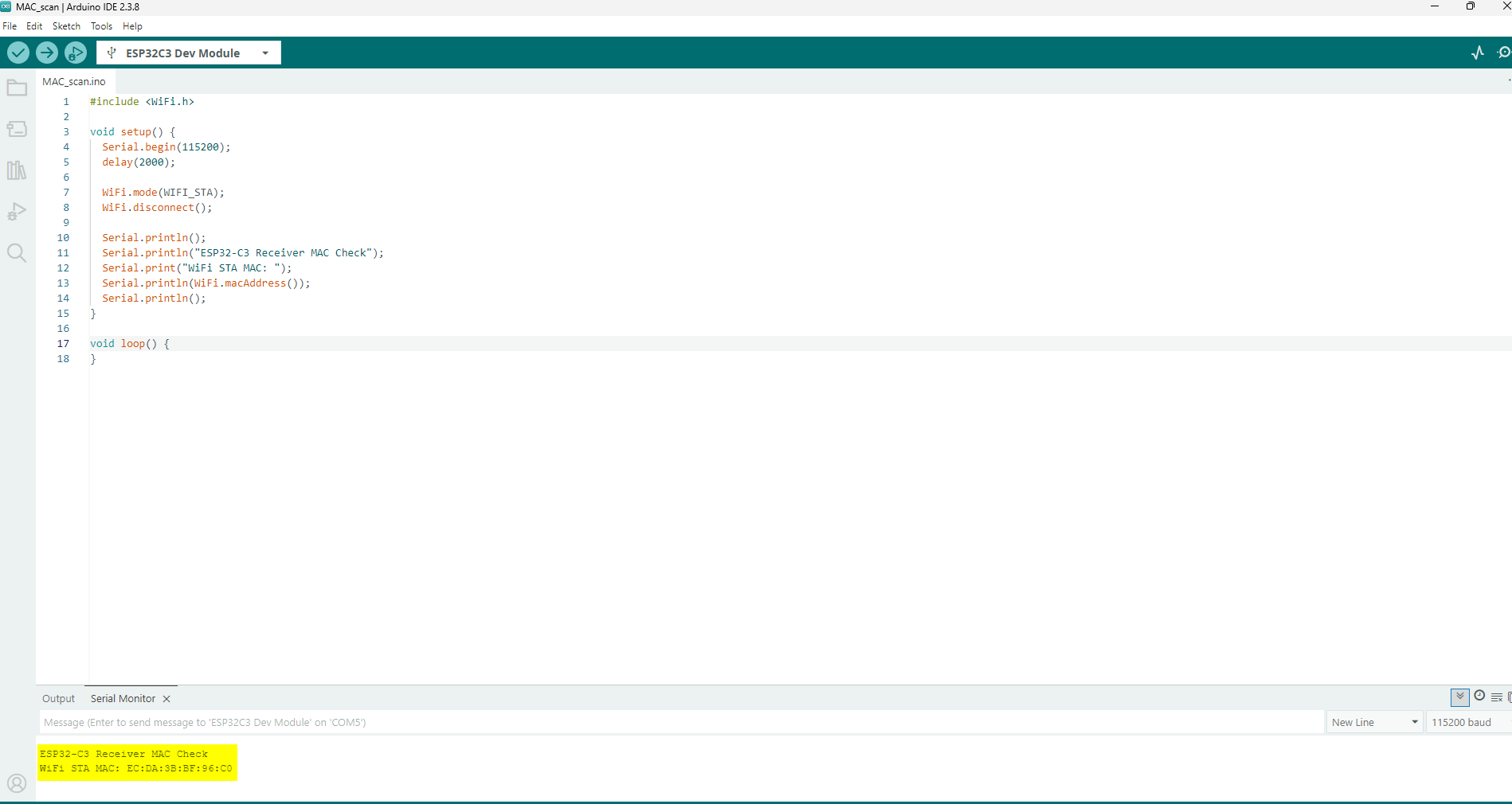
I first had to find the MAC address of the receiver (dev board).
For that, I used a small piece of code that ChatGPT generated for me.
An example prompt can be found here: ChatGPT example coding prompt
#include <WiFi.h>

void setup() {
  Serial.begin(115200);
  delay(2000);

  WiFi.mode(WIFI_STA);
  WiFi.disconnect();

  Serial.println();
  Serial.println("ESP32-C3 Receiver MAC Check");
  Serial.print("WiFi STA MAC: ");
  Serial.println(WiFi.macAddress());
  Serial.println();
}

void loop() {
}
I used this small helper code to determine the WiFi station MAC address of the ESP32-C3 receiver board.
This step was necessary as preparation for the later ESP-NOW communication setup, because the sender needs the unique MAC address of the receiver in order to transmit data to the correct device.
The sketch begins by including the WiFi.h library, which provides access to the WiFi functions of the microcontroller.
After a short startup delay, the board is configured in station mode using WiFi.mode(WIFI_STA).
This is important because the station MAC address is the relevant address for this communication setup.
The code then prints a short headline to the Serial Monitor and outputs the device’s current WiFi STA MAC address using WiFi.macAddress().
This address is later inserted into the ESP-NOW sender code so that the Sender board can send data packets directly to the receiver board.
In the larger project context, this step is directly connected to the use of the ESP-NOW library. ESP-NOW enables direct wireless communication between ESP32 boards without requiring a router or conventional WiFi network setup.
Instead of using IP-based communication, the devices identify each other via their MAC addresses.
The loop() function remains empty because this sketch is only intended as a one-time utility tool. Once the MAC address has been read from the Serial Monitor, the code has fulfilled its purpose.
After uploading the code, the MAC address was shown in the Serial Monitor, and I was then able to embed it into the sender code.
Sender Code
After that, I could begin defining the functions of the sender. First, I determined a suitable measurement range for the Time-of-Flight sensors. This range lies between 100 mm and 500 mm. The measured values are mapped to a range from 0 to 255 before they are transmitted by pressing a button.
In the Serial Monitor, the measured distances are displayed every second, and any distance above 500 mm is shown as “Out of Range”.
During transmission, only the values that lie within my defined measurement range are sent. Sensor 1 controls R (Red), Sensor 2 controls G (Green), and Sensor 3 controls B (Blue).
This also makes it possible to adjust and transmit only a single color channel if desired.
#include <Wire.h>
#include <VL53L0X.h>
#include <WiFi.h>
#include <esp_now.h>

// =========================
// Pin configuration
// =========================
constexpr uint8_t SDA_PIN    = 9;
constexpr uint8_t SCL_PIN    = 8;
constexpr uint8_t XSHUT1_PIN = 5;
constexpr uint8_t XSHUT2_PIN = 6;
constexpr uint8_t XSHUT3_PIN = 7;
constexpr uint8_t BUTTON_PIN = 10;

// =========================
// I2C addresses
// =========================
constexpr uint8_t SENSOR1_ADDR = 0x30;
constexpr uint8_t SENSOR2_ADDR = 0x31;
constexpr uint8_t SENSOR3_ADDR = 0x32;

// =========================
// General settings
// =========================
constexpr unsigned long PRINT_INTERVAL = 1000;  // ms
constexpr unsigned long DEBOUNCE_TIME  = 50;    // ms

constexpr int SENSOR_OFFSET_MM = 14;   // correction: measured distance - 14 mm
constexpr int RANGE_MIN_MM     = 100;  // valid range start
constexpr int RANGE_MAX_MM     = 500;  // valid range end

// =========================
// ESP-NOW receiver MAC
// =========================
uint8_t receiverMac[] = {0xEC, 0xDA, 0x3B, 0xBF, 0x96, 0xC0};

// =========================
// Sensor objects
// =========================
VL53L0X sensor1;
VL53L0X sensor2;
VL53L0X sensor3;

// =========================
// Runtime sensor data
// =========================
struct SensorReading {
  int rawMm = -1;
  int correctedMm = -1;
  uint8_t mapped = 0;
  bool valid = false;
};

SensorReading r1, r2, r3;

// =========================
// Data packet to send
// =========================
struct DataPacket {
  uint8_t valid1;
  uint8_t valid2;
  uint8_t valid3;
  uint8_t value1;
  uint8_t value2;
  uint8_t value3;
};

DataPacket packet;

// =========================
// Timing / button state
// =========================
unsigned long lastPrintTime = 0;

bool lastButtonReading = HIGH;
bool stableButtonState = HIGH;
unsigned long lastDebounceTime = 0;

// =========================
// Helper: print MAC address
// =========================
void printMacAddress(const uint8_t* mac) {
  for (int i = 0; i < 6; i++) {
    if (mac[i] < 16) Serial.print("0");
    Serial.print(mac[i], HEX);
    if (i < 5) Serial.print(":");
  }
  Serial.println();
}

// =========================
// ESP-NOW send callback
// =========================
void onDataSent(const esp_now_send_info_t *tx_info, esp_now_send_status_t status) {
  Serial.print("ESP-NOW send status");

  if (tx_info != nullptr && tx_info->des_addr != nullptr) {
    Serial.print(" to ");
    printMacAddress(tx_info->des_addr);
  } else {
    Serial.println();
  }

  if (status == ESP_NOW_SEND_SUCCESS) {
    Serial.println("Transmission successful");
  } else {
    Serial.println("Transmission failed");
  }
  Serial.println();
}

// =========================
// Safe VL53L0X read helper
// =========================
bool readDistanceMm(VL53L0X& sensor, int& distanceMm) {
  int reading = sensor.readRangeContinuousMillimeters();

  if (sensor.timeoutOccurred()) {
    return false;
  }

  if (reading <= 0 || reading >= 8190) {
    return false;
  }

  distanceMm = reading;
  return true;
}

// =========================
// Convert corrected distance
// to 0...255
// 100 mm -> 0
// 500 mm -> 255
// =========================
uint8_t mapDistanceToByte(int correctedMm) {
  long mapped = map(correctedMm, RANGE_MIN_MM, RANGE_MAX_MM, 0, 255);

  if (mapped < 0)   mapped = 0;
  if (mapped > 255) mapped = 255;

  return static_cast<uint8_t>(mapped);
}

// =========================
// Process one sensor reading
// =========================
void updateSensorReading(VL53L0X& sensor, SensorReading& reading) {
  int raw = -1;
  bool ok = readDistanceMm(sensor, raw);

  reading.rawMm = -1;
  reading.correctedMm = -1;
  reading.mapped = 0;
  reading.valid = false;

  if (!ok) {
    return;
  }

  reading.rawMm = raw;
  reading.correctedMm = raw - SENSOR_OFFSET_MM;

  if (reading.correctedMm >= RANGE_MIN_MM && reading.correctedMm <= RANGE_MAX_MM) {
    reading.valid = true;
    reading.mapped = mapDistanceToByte(reading.correctedMm);
  }
}

// =========================
// Serial output helper
// =========================
void printSensorLine(const char* name, const SensorReading& r) {
  Serial.print(name);
  Serial.print(": ");

  if (r.rawMm < 0) {
    Serial.println("invalid");
    return;
  }

  Serial.print(r.correctedMm);
  Serial.print(" mm");

  if (r.valid) {
    Serial.print(" -> ");
    Serial.print(r.mapped);
  } else {
    Serial.print(" -> Out of Range");
  }

  Serial.println();
}

// =========================
// Read all sensors continuously
// =========================
void updateAllSensors() {
  updateSensorReading(sensor1, r1);
  updateSensorReading(sensor2, r2);
  updateSensorReading(sensor3, r3);
}

// =========================
// Print all sensor values
// every 1 second
// =========================
void printAllSensorsIfDue() {
  unsigned long now = millis();

  if (now - lastPrintTime < PRINT_INTERVAL) {
    return;
  }

  Serial.println("Current sensor values:");
  printSensorLine("S1", r1);
  printSensorLine("S2", r2);
  printSensorLine("S3", r3);
  Serial.println();

  lastPrintTime = now;
}

// =========================
// Build packet from current data
// =========================
void buildPacket() {
  packet.valid1 = r1.valid ? 1 : 0;
  packet.valid2 = r2.valid ? 1 : 0;
  packet.valid3 = r3.valid ? 1 : 0;

  packet.value1 = r1.valid ? r1.mapped : 0;
  packet.value2 = r2.valid ? r2.mapped : 0;
  packet.value3 = r3.valid ? r3.mapped : 0;
}

// =========================
// Send current packet
// =========================
void sendCurrentPacket() {
  buildPacket();

  Serial.println("Button pressed -> sending packet");

  Serial.print("S1: ");
  if (packet.valid1) Serial.println(packet.value1);
  else Serial.println("not sent (Out of Range)");

  Serial.print("S2: ");
  if (packet.valid2) Serial.println(packet.value2);
  else Serial.println("not sent (Out of Range)");

  Serial.print("S3: ");
  if (packet.valid3) Serial.println(packet.value3);
  else Serial.println("not sent (Out of Range)");

  esp_err_t result = esp_now_send(receiverMac, reinterpret_cast<uint8_t*>(&packet), sizeof(packet));

  if (result == ESP_OK) {
    Serial.println("Packet queued for transmission");
  } else {
    Serial.print("Error while sending packet: ");
    Serial.println(result);
  }

  Serial.println();
}

// =========================
// Button handling
// INPUT_PULLUP:
// released = HIGH
// pressed  = LOW
// =========================
void handleButton() {
  bool reading = digitalRead(BUTTON_PIN);

  if (reading != lastButtonReading) {
    lastDebounceTime = millis();
  }

  if ((millis() - lastDebounceTime) > DEBOUNCE_TIME) {
    if (reading != stableButtonState) {
      stableButtonState = reading;

      if (stableButtonState == LOW) {
        sendCurrentPacket();
      }
    }
  }

  lastButtonReading = reading;
}

// =========================
// Sensor initialization
// =========================
bool initSensors() {
  pinMode(XSHUT1_PIN, OUTPUT);
  pinMode(XSHUT2_PIN, OUTPUT);
  pinMode(XSHUT3_PIN, OUTPUT);

  digitalWrite(XSHUT1_PIN, LOW);
  digitalWrite(XSHUT2_PIN, LOW);
  digitalWrite(XSHUT3_PIN, LOW);
  delay(100);

  // -------- Sensor 1 --------
  digitalWrite(XSHUT1_PIN, HIGH);
  delay(100);

  if (!sensor1.init()) {
    Serial.println("Error: Sensor 1 init failed.");
    return false;
  }
  sensor1.setAddress(SENSOR1_ADDR);
  sensor1.setTimeout(100);
  sensor1.startContinuous();
  Serial.println("Sensor 1 ready at 0x30");

  // -------- Sensor 2 --------
  digitalWrite(XSHUT2_PIN, HIGH);
  delay(100);

  if (!sensor2.init()) {
    Serial.println("Error: Sensor 2 init failed.");
    return false;
  }
  sensor2.setAddress(SENSOR2_ADDR);
  sensor2.setTimeout(100);
  sensor2.startContinuous();
  Serial.println("Sensor 2 ready at 0x31");

  // -------- Sensor 3 --------
  digitalWrite(XSHUT3_PIN, HIGH);
  delay(100);

  if (!sensor3.init()) {
    Serial.println("Error: Sensor 3 init failed.");
    return false;
  }
  sensor3.setAddress(SENSOR3_ADDR);
  sensor3.setTimeout(100);
  sensor3.startContinuous();
  Serial.println("Sensor 3 ready at 0x32");

  return true;
}

// =========================
// ESP-NOW initialization
// =========================
bool initEspNow() {
  WiFi.mode(WIFI_STA);
  WiFi.disconnect();

  Serial.print("Sender STA MAC: ");
  Serial.println(WiFi.macAddress());

  if (esp_now_init() != ESP_OK) {
    Serial.println("ESP-NOW initialization failed");
    return false;
  }

  esp_now_register_send_cb(onDataSent);

  esp_now_peer_info_t peerInfo = {};
  memcpy(peerInfo.peer_addr, receiverMac, 6);
  peerInfo.channel = 0;
  peerInfo.encrypt = false;

  if (esp_now_add_peer(&peerInfo) != ESP_OK) {
    Serial.println("Failed to add receiver as peer");
    return false;
  }

  Serial.print("Receiver peer added: ");
  printMacAddress(receiverMac);

  return true;
}

// =========================
// Setup
// =========================
void setup() {
  Serial.begin(115200);
  delay(2000);

  Serial.println();
  Serial.println("ESP32-C3 Sender");
  Serial.println("3x VL53L0X + ESP-NOW");
  Serial.println("Initializing...");
  Serial.println();

  Wire.begin(SDA_PIN, SCL_PIN);
  Wire.setClock(100000);

  pinMode(BUTTON_PIN, INPUT_PULLUP);

  if (!initSensors()) {
    Serial.println("Sensor initialization failed. Stopping here.");
    while (true) {
      delay(1000);
    }
  }

  if (!initEspNow()) {
    Serial.println("ESP-NOW setup failed. Stopping here.");
    while (true) {
      delay(1000);
    }
  }

  Serial.println();
  Serial.println("System ready.");
  Serial.println("Continuous measurement active.");
  Serial.println("Press button to send current valid values.");
  Serial.println();
}

// =========================
// Main loop
// =========================
void loop() {
  updateAllSensors();
  printAllSensorsIfDue();
  handleButton();
}
Receiver Code
On the receiver side, a data packet with 0 to 3 values, each ranging from 0 to 255, is received. Since I still want to protect the LED strip for now, I limited the maximum brightness to 70%.
For that, the received values were scaled accordingly. By pressing the button, the latest color values are transferred to the WS2812B LED strip.
The values are initialized with 0, so pressing the reset button on the ESP resets the color values as well. During the reset process, however, no data transmission is possible, which is why I would implement this function differently in the future.
#include <WiFi.h>
#include <esp_now.h>
#include <FastLED.h>

// =========================
// LED / Button configuration
// =========================
#define STATUS_LED_PIN 1
#define LED_PIN        6
#define BUTTON_PIN     A0
#define NUM_LEDS       144
#define LED_TYPE       WS2812B
#define COLOR_ORDER    GRB

// =========================
// Brightness
// 70% of 255 = 178.5 -> 179
// =========================
constexpr uint8_t MAX_BRIGHTNESS = 179;

// =========================
// Timing
// =========================
constexpr unsigned long PRINT_INTERVAL = 1000;
constexpr unsigned long DEBOUNCE_TIME  = 50;

// =========================
// LED buffer
// =========================
CRGB leds[NUM_LEDS];

// =========================
// Stored RGB values
// These are the values that are
// currently stored from received packets
// and will be shown on button press
// =========================
uint8_t RED   = 0;
uint8_t GREEN = 0;
uint8_t BLUE  = 0;

// =========================
// Last received packet values
// (for debug / transparency)
// =========================
uint8_t lastRxValue1 = 0;
uint8_t lastRxValue2 = 0;
uint8_t lastRxValue3 = 0;
bool lastRxValid1 = false;
bool lastRxValid2 = false;
bool lastRxValid3 = false;

// =========================
// Receive state / debug
// =========================
bool newPacketReceived = false;
unsigned long packetCounter = 0;
unsigned long lastPrintTime = 0;

// =========================
// Button state
// INPUT_PULLUP:
// released = HIGH
// pressed  = LOW
// =========================
bool lastButtonReading = HIGH;
bool stableButtonState = HIGH;
unsigned long lastDebounceTime = 0;

// =========================
// Data packet from sender
// Must match the sender struct exactly
// =========================
struct DataPacket {
  uint8_t valid1;
  uint8_t valid2;
  uint8_t valid3;
  uint8_t value1;
  uint8_t value2;
  uint8_t value3;
};

// =========================
// Status LED blink request
// We only set a flag in callbacks
// and blink later in loop()
// =========================
bool blinkRequest = false;

// =========================
// Helper: print MAC address
// =========================
void printMacAddress(const uint8_t* mac) {
  for (int i = 0; i < 6; i++) {
    if (mac[i] < 16) Serial.print("0");
    Serial.print(mac[i], HEX);
    if (i < 5) Serial.print(":");
  }
  Serial.println();
}

// =========================
// Update LED strip
// =========================
void updateLEDs() {
  fill_solid(leds, NUM_LEDS, CRGB(RED, GREEN, BLUE));
  FastLED.show();
}

// =========================
// Short visual feedback
// =========================
void runStatusBlinkIfRequested() {
  if (!blinkRequest) {
    return;
  }

  blinkRequest = false;

  digitalWrite(STATUS_LED_PIN, HIGH);
  delay(80);
  digitalWrite(STATUS_LED_PIN, LOW);
}

// =========================
// ESP-NOW receive callback
// Keep this short
// =========================
void onDataRecv(const esp_now_recv_info_t *recvInfo, const uint8_t *incomingData, int len) {
  if (len != sizeof(DataPacket)) {
    return;
  }

  DataPacket packet;
  memcpy(&packet, incomingData, sizeof(packet));

  // Save received values for debug
  lastRxValid1 = (packet.valid1 == 1);
  lastRxValid2 = (packet.valid2 == 1);
  lastRxValid3 = (packet.valid3 == 1);

  lastRxValue1 = packet.value1;
  lastRxValue2 = packet.value2;
  lastRxValue3 = packet.value3;

  // Update only values that were actually transmitted
  // Missing values keep their previous stored state
  if (packet.valid1) {
    RED = packet.value1;
  }
  if (packet.valid2) {
    GREEN = packet.value2;
  }
  if (packet.valid3) {
    BLUE = packet.value3;
  }

  packetCounter++;
  newPacketReceived = true;
  blinkRequest = true;
}

// =========================
// Button handling
// On button press, show the currently
// stored RGB values on the LED strip
// =========================
void handleButton() {
  bool reading = digitalRead(BUTTON_PIN);

  if (reading != lastButtonReading) {
    lastDebounceTime = millis();
  }

  if ((millis() - lastDebounceTime) > DEBOUNCE_TIME) {
    if (reading != stableButtonState) {
      stableButtonState = reading;

      if (stableButtonState == LOW) {
        Serial.println("Receiver button pressed -> showing stored RGB values");
        Serial.print("Applying R: ");
        Serial.print(RED);
        Serial.print(" | G: ");
        Serial.print(GREEN);
        Serial.print(" | B: ");
        Serial.println(BLUE);
        Serial.println();

        updateLEDs();

        digitalWrite(STATUS_LED_PIN, HIGH);
        delay(120);
        digitalWrite(STATUS_LED_PIN, LOW);
        delay(80);
        digitalWrite(STATUS_LED_PIN, HIGH);
        delay(120);
        digitalWrite(STATUS_LED_PIN, LOW);
      }
    }
  }

  lastButtonReading = reading;
}

// =========================
// Periodic serial output
// =========================
void printStatusIfDue() {
  unsigned long now = millis();

  if (now - lastPrintTime < PRINT_INTERVAL) {
    return;
  }

  lastPrintTime = now;

  Serial.print("Stored RGB -> R: ");
  Serial.print(RED);
  Serial.print(" | G: ");
  Serial.print(GREEN);
  Serial.print(" | B: ");
  Serial.print(BLUE);

  Serial.print(" | Last packet #: ");
  Serial.print(packetCounter);

  Serial.print(" | Button raw: ");
  Serial.println(digitalRead(BUTTON_PIN));

  Serial.print("Last RX packet -> ");
  Serial.print("S1: ");
  if (lastRxValid1) Serial.print(lastRxValue1);
  else Serial.print("not transmitted");

  Serial.print(" | S2: ");
  if (lastRxValid2) Serial.print(lastRxValue2);
  else Serial.print("not transmitted");

  Serial.print(" | S3: ");
  if (lastRxValid3) Serial.println(lastRxValue3);
  else Serial.println("not transmitted");

  if (newPacketReceived) {
    Serial.println("New packet has been received and stored.");
    newPacketReceived = false;
  }

  Serial.println();
}

// =========================
// ESP-NOW initialization
// =========================
bool initEspNowReceiver() {
  WiFi.mode(WIFI_STA);
  WiFi.disconnect();

  Serial.print("Receiver STA MAC: ");
  Serial.println(WiFi.macAddress());

  if (esp_now_init() != ESP_OK) {
    Serial.println("ESP-NOW initialization failed");
    return false;
  }

  if (esp_now_register_recv_cb(onDataRecv) != ESP_OK) {
    Serial.println("Failed to register receive callback");
    return false;
  }

  Serial.println("ESP-NOW receiver ready");
  return true;
}

// =========================
// Setup
// =========================
void setup() {
  pinMode(BUTTON_PIN, INPUT_PULLUP);
  pinMode(STATUS_LED_PIN, OUTPUT);
  digitalWrite(STATUS_LED_PIN, LOW);

  Serial.begin(115200);
  delay(2000);

  Serial.println();
  Serial.println("ESP32-C3 Receiver");
  Serial.println("ESP-NOW + FastLED");
  Serial.println();

  FastLED.addLeds<LED_TYPE, LED_PIN, COLOR_ORDER>(leds, NUM_LEDS);
  FastLED.setBrightness(MAX_BRIGHTNESS);
  FastLED.clear();
  FastLED.show();

  if (!initEspNowReceiver()) {
    Serial.println("Receiver setup failed. Stopping here.");
    while (true) {
      delay(1000);
    }
  }

  Serial.println();
  Serial.println("System ready.");
  Serial.println("Waiting for packets...");
  Serial.println("Press local button to show currently stored RGB values.");
  Serial.println();
}

// =========================
// Main loop
// =========================
void loop() {
  handleButton();
  runStatusBlinkIfRequested();
  printStatusIfDue();
}
Video
The wiring of the sender is the same as in week 9. The receiver is connected in the same way as in week 10.
First, I used my palm to adjust a color value and transmitted it by pressing the button. After pressing the button on the receiver side, the received value was shown on the LED strip.
Downloads
MAC_scan.ino
Sender.ino
Receiver.ino