System Integration
This week’s goal was to design and document how the individual parts of my final project come together as one integrated system.
Introduction
System integration means bringing separate technical parts together so that they no longer work only as isolated prototypes, but as one complete and functional system. It includes the combination of mechanical design, electronics, software, power supply, user interaction, and the overall appearance of the final device.
For my final project, this means integrating all individual parts of my contactless lamp system into a coherent final concept. The project is not only one single object, but consists of two connected products: a sender unit, which detects the user input, and a receiver unit, which is the actual lamp. The main focus of this week was therefore to define how these two parts work together and how the electronics, software, and user interaction are connected in a clean and reliable way.
The tests and prototypes from the previous weeks form the technical basis for this integration. During those weeks, I tested and developed individual components such as sensors, LED control, communication, input handling, and output behavior. In this week, the goal was to move beyond these separate tests and develop them into one functional overall system.
Besides the technical integration, the visual appearance of the final project is also an important part of the system design. Since the lamp is meant to be used as a visible object in a room, the electronics and mechanics should not only work reliably, but also be integrated in a way that looks intentional, clean, and product-like.
Final Project System Overview
My final project is a contactless, color-controllable floor lamp. The lamp itself uses individually addressable WS2812B LEDs, which makes it possible to control the color and brightness of each LED segment through software. Instead of using a conventional switch or rotary knob, the lamp is controlled by a separate sender unit that works as a small table element.
The complete system consists of two connected products: the lamp as the receiver unit and the separate control unit as the sender unit. This separation is important for the user experience, because the lamp can stand in the room as a clean visual object, while the interaction happens at a more comfortable position, for example on a table.
The sender unit contains three VL53L0X Time-of-Flight sensors and one button. The sensors are used to measure the distance of the user’s hand without physical contact. Each sensor can represent one RGB color channel. By moving the hand closer to or further away from the sensors, the user can change the color values and therefore mix the final light color of the lamp in an intuitive way. The button on the sender unit can be used for switching between different modes or confirming an input.
The receiver side is the lamp itself. It includes the lamp body, the lamp base, the LED strip, the diffuser, the receiver electronics, a relay for switching, and the internal cable routing. The electronics in the lamp base receive or process the control information and drive the LED strip. The diffuser is an important part of the visual design, because it softens the light from the individual LEDs and makes the lamp look less like a technical prototype and more like a finished product.
The main parts of the system are:
- Lamp body
- WS2812B LED strip
- Diffuser
- Lamp base with receiver electronics
- Sender / control unit
- ESP32-C3 microcontrollers
- Three VL53L0X Time-of-Flight sensors
- Button on the sender unit
- Relay for switching the lamp
- Power supply
- Internal wiring and cable routing
The basic function of the system is to allow contactless color control of the lamp. The user should be able to adjust the red, green, and blue values by interacting with the three distance sensors. This creates a more playful and experimental way of controlling light than a normal lamp switch.
Since the color and behavior of the LEDs are controlled through software, the system is also very flexible. Besides the basic RGB color control, many alternative modes are possible. Depending on the remaining development time, additional modes could be added, for example a slow color-fading mode, some lighting-engineer modes like a stroboscope effect or even individually adressed effects. These modes would require no hardware changes, because the sensors, button, microcontrollers, and addressable LEDs already provide all necessary input and output possibilities. The behavior can be changed completely in software.
The intended final user experience is that the lamp feels like an interactive object rather than a normal static light source. The user places the sender unit on a table, moves their hand above the sensors, and immediately sees the effect on the lamp. The interaction should feel direct, understandable, and visually satisfying. At the same time, the lamp itself should remain clean and minimal in appearance, with the technical parts integrated into the base and the light output softened by the diffuser.
System Architecture
The system architecture is divided into two main units: the sender unit and the receiver unit.
The sender unit is responsible for detecting the user input. It contains three VL53L0X Time-of-Flight sensors, which are connected to an ESP32-C3 microcontroller. Each sensor measures the distance of the user’s hand and can be used to control one color channel of the RGB light output. In addition to the sensors, the sender unit also includes a button, which can be used for mode switching or additional user input. The sender is powered through USB-C, which is routed to the outside of the housing.
Mechanically, the sender unit is planned as a small and flat wooden table element. The body will be made from wood, with the three sensors placed inside the housing on a screw-mounted development board. The exact height and final proportions are still being tested, because the unit should be as flat as possible while still leaving enough space for the electronics and wiring.
The sensors are positioned below three small openings on the top side of the housing. From the outside, only these small sensor openings should be visible, while the rest of the body should remain clean and minimal. To protect the sensors, small strips of thin microscope slide glass are planned above the openings. This keeps the sensors protected from direct contact while still allowing distance measurements through the top surface.
For the mechanical fixation, I want to use metric screws together with threaded inserts for wood, such as Rampa inserts. This allows the development board and the bottom cover to be screwed into the wooden housing in a reliable and reusable way. The bottom side of the sender unit will have an access opening, fixed with six screws. This makes it possible to open the housing later for debugging, repairs, or changes to the electronics.
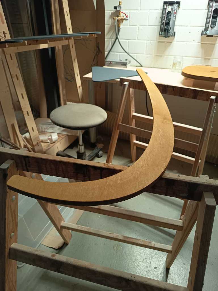
The receiver unit is the lamp itself. It consists of a stable and relatively heavy base, the lamp body, the LED strip, the diffuser, and the internal electronics. The base will probably be made from stained multiplex plywood, because it provides enough weight and stability for the floor lamp. Inside the base, there will be another ESP32-C3 with its PCB, the relay, and the required wiring. The connection from the base to the lamp body will be routed through a small hole at a suitable position, so that the cable path stays hidden and clean.
The lamp body will be made from ash wood. A groove will be milled into the body to hold the WS2812B LED strip and the diffuser. The LED strip sits inside this groove, while the diffuser is glued into the same area to soften the light and hide the individual LED points. This part is especially important for the final appearance of the lamp, because the light output should look smooth and intentional rather than like a visible LED strip.
Similar to the sender unit, the receiver base will also include an access opening on the bottom side. This opening will be fixed with four metric screws and threaded inserts. The goal is to keep the electronics protected and hidden during normal use, but still accessible for maintenance, programming, and troubleshooting.
Overall, the system architecture follows a modular structure. The sender unit handles the user interaction and distance sensing, while the receiver unit handles the light output and the physical lamp structure. This separation makes the interaction more flexible, because the user can place the control unit on a table while the lamp itself stays in the desired position in the room.
Electronics Packaging and Mechanical Integration
The goal of the electronics packaging is to avoid loose parts and temporary prototype wiring. The boards should be fixed mechanically, the wires should be routed in a controlled way, and the important components should remain accessible for testing and debugging.
The electronics are packaged inside the sender unit and the receiver base. In the sender unit, the ESP32-C3 development board, the three VL53L0X sensors, the button, and the USB-C power connection are mounted inside the wooden housing. In the receiver unit, the ESP32-C3, PCB, relay, and wiring are placed inside the lamp base.
A main design goal is to hide the technical components as much as possible. The electronics are placed inside the housings, while only the sensor openings and the button, remain visible. For the lamp body, the LED strip and diffuser are integrated into a milled groove. This keeps the visible part of the lamp clean so that the light output becomes part of the wooden structure, and protects the electronics during normal use.
Wiring and Power Distribution
The sender unit is powered through USB-C. Inside the sender housing, the ESP32-C3 supplies and communicates with the three VL53L0X sensors through the I²C bus. The XSHUT pins of the sensors are used so that each sensor can receive its own I²C address.
The receiver unit contains the power distribution for the lamp. The WS2812B LED strip requires a stable 5 V supply, while the ESP32-C3 controls the LED data signal. A common ground connection is required between the microcontroller and the LED strip. The microcontroller controls a relay because the current of the WS2812B LED strip is approximately 3 A.
The wiring is routed inside the housings. The goal is to keep the cable paths hidden, protected, and mechanically relieved so that the final object does not look like a temporary prototype.
Integration Tests
The integration tests are used to check whether the separate components work together as one complete system.
| Test | Purpose | Expected Result |
|---|---|---|
| Sensor test (with glass) | Check if all VL53L0X sensors measure distance correctly | Stable distance values from all three sensors |
| I²C address test | Check if the three sensors can work on the same bus | Each sensor receives its own address |
| Button test | Check if the button input is detected reliably | Button press changes or confirms a mode |
| LED test | Check if the WS2812B strip responds correctly | LEDs show the intended colors and effects |
| Power test | Check if the power supply is sufficient | System runs without resets or unstable behavior |
| Mechanical fit test | Check if electronics and wiring fit inside the housings | Housing can be closed without stress on parts |
| User interaction test | Check if the control concept feels understandable | Hand movement creates visible changes on the lamp |
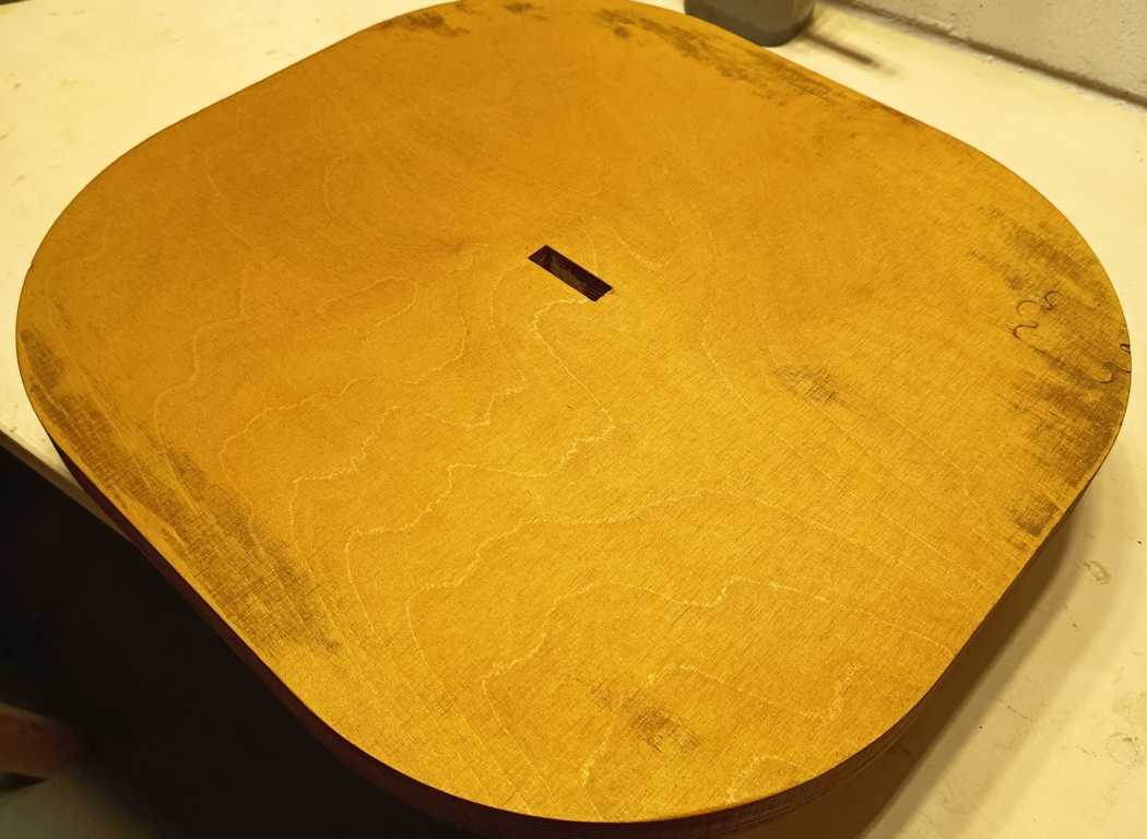
| Stain test | Check if the color looks good | 1x should look only a bit darker, 3x should appear in the desired teak wood |
Prototype lamp (multiplex birch with “teak” wood stain):
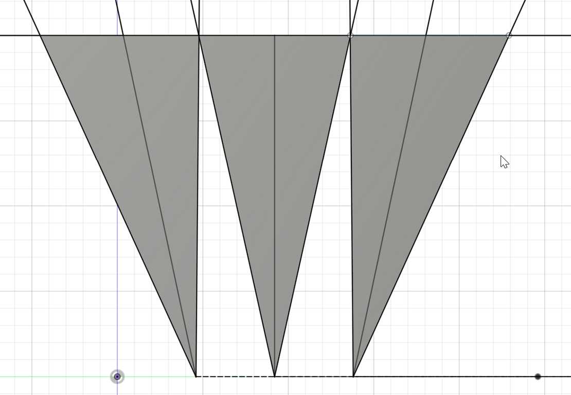
ToF Sensor adapters
To determine the minimum spacing between the three sensors, I carried out several calculations. I slightly tilted the two outer sensors so that they could be placed closer together while still covering the required interaction area. With a field of view of 25° and a tilt angle of 12°, I calculated an optimal sensor spacing of 115 mm. This allows reliable and smooth operation at distances of up to 500 mm.