Output Devices
This week’s goal was to measure the power consumption of an output device as a group and individually integrate and program an output device on a self-designed microcontroller board. Link to our Group Page
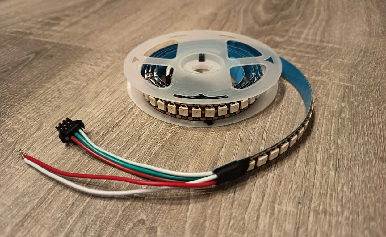
WS2812B LED
WS2812B LEDs are digitally addressable RGB LEDs in which each individual LED contains its own integrated control circuit.
The WS2812B integrates the RGB LED and the control electronics into a single 5050 package, which makes it possible to control many LEDs through only a single data line.
Each pixel can be addressed individually and uses 24-bit color data, allowing precise control over red, green, and blue values.
One of the main advantages of these LEDs is that they simplify the wiring significantly compared to conventional RGB LEDs. Instead of controlling separate red, green, and blue channels for the entire strip, each LED receives digital data, extracts its own information, and forwards the remaining signal to the next LED in the chain. Another useful feature is the internal signal reshaping, which helps to maintain signal quality across cascaded chains. The system is based on a supply voltage of around 5 V, and the reset time must be greater than 50 µs.
Since I decided to build an LED floor lamp for my final project, it makes sense to carry out the first tests with this type of LED now. This allows me to determine the power consumption more precisely later on and also get a first impression of the brightness over a full meter of LED strip.
For the code, I asked ChatGPT to generate a simple code that displays a random color when a button is pressed. The RGB values are set randomly between 0 and 255 and then displayed using FastLED.show().
#include <FastLED.h>

#define STATUS_LED_PIN 1
#define LED_PIN        6
#define BUTTON_PIN     A0
#define NUM_LEDS       144
#define LED_TYPE       WS2812B
#define COLOR_ORDER    GRB

CRGB leds[NUM_LEDS];

uint8_t RED   = 255;
uint8_t GREEN = 20;
uint8_t BLUE  = 147;

unsigned long lastPrintTime = 0;
const unsigned long printInterval = 1000;

bool buttonPressed = false;

void setup() {
  pinMode(BUTTON_PIN, INPUT_PULLUP);
  pinMode(STATUS_LED_PIN, OUTPUT);
  digitalWrite(STATUS_LED_PIN, LOW);

  Serial.begin(115200);

  FastLED.addLeds<LED_TYPE, LED_PIN, COLOR_ORDER>(leds, NUM_LEDS);
  FastLED.clear();
  FastLED.show();

  randomSeed(analogRead(A2));

  updateLEDs();
}

void loop() {
  if (digitalRead(BUTTON_PIN) == LOW && !buttonPressed) {
    buttonPressed = true;

    Serial.println("Button pressed");

    digitalWrite(STATUS_LED_PIN, HIGH);
    delay(300);
    digitalWrite(STATUS_LED_PIN, LOW);
    delay(200);
    digitalWrite(STATUS_LED_PIN, HIGH);
    delay(300);
    digitalWrite(STATUS_LED_PIN, LOW);

    RED   = random(0, 256);
    GREEN = random(0, 256);
    BLUE  = random(0, 256);

    updateLEDs();
  }

  if (digitalRead(BUTTON_PIN) == HIGH) {
    buttonPressed = false;
  }

  if (millis() - lastPrintTime >= printInterval) {
    lastPrintTime = millis();

    Serial.print("R: ");
    Serial.print(RED);
    Serial.print(" | G: ");
    Serial.print(GREEN);
    Serial.print(" | B: ");
    Serial.print(BLUE);
    Serial.print(" | Button raw: ");
    Serial.println(digitalRead(BUTTON_PIN));
  }
}

void updateLEDs() {
  fill_solid(leds, NUM_LEDS, CRGB(RED, GREEN, BLUE));
  FastLED.show();
}
After flashing the code, I could begin with the wiring.
I connected a external power supply with 5 V to the LED strip. The V+ terminal was connected to the red wire and V- to the white wire of the strip. I used pin 6 of my dev board as the data channel and connected this GPIO pin to the green wire.
Testing
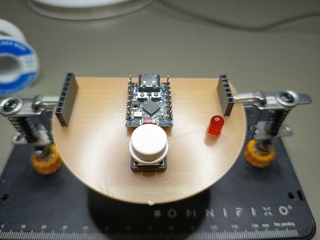
This is my PCB from week 8:
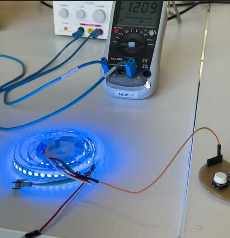
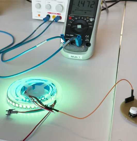
I also connected a multimeter in series with the circuit to measure the current. This allowed me to see how the current consumption changes depending on the selected color values.
The measurement also showed why the LED strip should not be powered directly from the ESP. At this load, the current would be far too high and the ESP would most likely be damaged.