Interface And Application Programming
This week’s goal was to write an application that allows a user to interact with an input and/or output device I made and to compare a wide range of available tool options as a group.
Introduction
Application and interface programming describes the development of software that allows users to interact with a technical system.
While embedded programming focuses on the behavior of the microcontroller itself, interface programming focuses on the connection between the user and the machine.
An interface can have many different forms.
It can be a graphical user interface on a computer, a mobile app, a web interface, a touchscreen, a physical control panel, or even a simple serial monitor.
The main purpose is always the same: information from the system should become understandable for the user, and user input should be translated into actions inside the system.
Historically, early computers were mainly controlled through switches, punched cards, or command-line interfaces.
Over time, graphical user interfaces became more important because they made computers easier to use for non-specialists.
Today, interfaces are everywhere: in smartphones, machines, cars, industrial systems, home automation, medical devices, and digital fabrication tools.
In digital fabrication and embedded systems, application programming is especially important because it connects hardware and software.
A microcontroller can read sensors, control actuators, and process data, but without a useful interface it can be difficult to understand or control the system.
An interface makes the internal state of a system visible and allows the user to change parameters, start actions, or monitor results.
A good interface should be simple, understandable, and reliable. It should show only the information that is necessary and make interaction as direct as possible.
Especially in prototyping, the interface does not need to be visually perfect, but it should clearly demonstrate the communication between the application and the embedded system.
For this reason, interface programming is not only about designing buttons and screens. It is about creating a functional connection between humans, software, and physical hardware. In the context of FabAcademy, this is an important step because it shows how a digital fabrication project can become more usable, testable, and interactive.
Building the App Interface with MIT App Inventor
For this week I wanted to build a very simple mobile application that interfaces directly with my own input device.
The input device was my ESP32-C3 based ToF board with three VL53L0X distance sensors.
The board sends the three measured distance values via Bluetooth Low Energy, and the app receives and displays them on the phone.
I deliberately kept the app very basic. The main goal was not to design a complex user interface, but to create a reliable connection between the user, the mobile phone, and my physical input board.
For the assignment it was more important that the data flow works clearly and that the user can directly see the live sensor values.
MIT App Inventor Overview
Before building the actual app, I first used the MIT App Inventor interface to understand how the app is structured.
MIT App Inventor is divided into two main working areas: the Designer and the Blocks editor.
In the Designer view, the visual layout of the app is created. Components such as buttons, labels, lists, and extensions can be added by dragging them from the palette into the phone preview. This makes it easy to quickly build a simple user interface without writing traditional Android code.
The main areas of the Designer are:
- Palette contains all available UI components and extensions.
- Viewer shows the phone screen and the current app layout.
- Components lists all elements that are already part of the app.
- Properties allows editing the selected component, for example its text, size, alignment, or color.
- Non-visible components contains components that do not appear directly on the screen, such as the BluetoothLE extension.
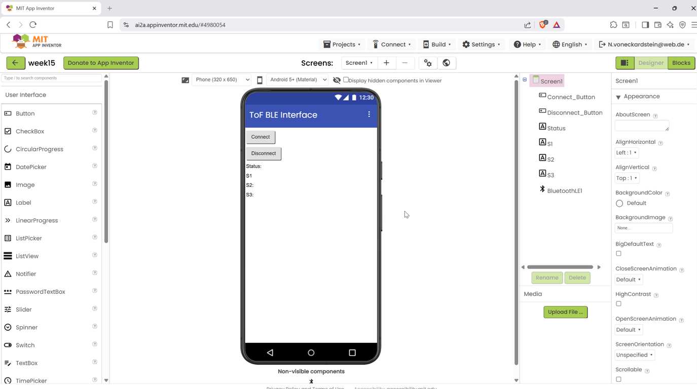
For this assignment, I used the Designer mainly to build a minimal interface with a connection button, a disconnect button, a status label, and three labels for the sensor values.
Desired Properties of the ToF App
The app should fulfil only a few clear functions:
- Connect to my ESP32-C3 ToF board via Bluetooth Low Energy.
- Receive a data packet containing three sensor values.
- Split the received data into three separate values.
- Display the three live ToF sensor readings on the phone.
- Keep the interface simple and understandable.
The ESP32 sends the data in a compact comma-separated format:
For example:
245,318,129
I choosed this format because it is short, reliable, and easy to parse in MIT App Inventor. Instead of sending complex JSON data, I used a simple string format because the app only needs to display three values.
Designing the App Overlay
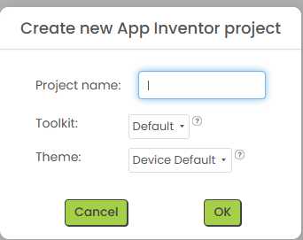
I started by creating a new project in MIT App Inventor.
The visual layout was intentionally kept very basic, because I wanted the final app to focus only on the live sensor values.
First, I added a title label to make the purpose of the app clear. Then I added a Connect button and a Disconnect button. These buttons allow the user to manually start and stop the BLE connection.
After that, I added three separate labels for the sensor values:
S1: - S2: - S3: -
Each label represents one of the three VL53L0X ToF sensors on my board. When the app receives new data from the ESP32-C3, these labels are updated with the current distance values in millimetres.
Finally, I imported the BluetoothLE extension into the project.
Extensions
This component is not visible in the app interface, but it is required for the BLE communication. It allows the app to connect to the ESP32-C3, subscribe to incoming data, and receive the sensor values.
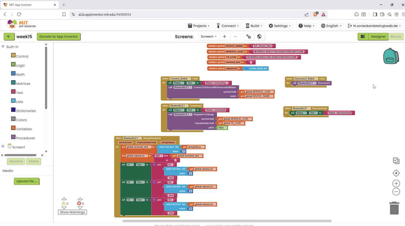
Building the App Logic
After creating the visual layout, I switched to the Blocks editor. The Blocks editor defines how the app reacts to user actions and incoming BLE data.
Global Variables
First, I created global variables for the BLE device name and the UUIDs. These values have to match the values used in the ESP32-C3 firmware.
initialize global DEVICE_NAME to "ToF_Board_Nico"

initialize global SERVICE_UUID to
"6E400001-B5A3-F393-E0A9-E50E24DCCA9E"

initialize global TX_UUID to
"6E400003-B5A3-F393-E0A9-E50E24DCCA9E"

initialize global receivedText to ""

initialize global valuesList to create empty list
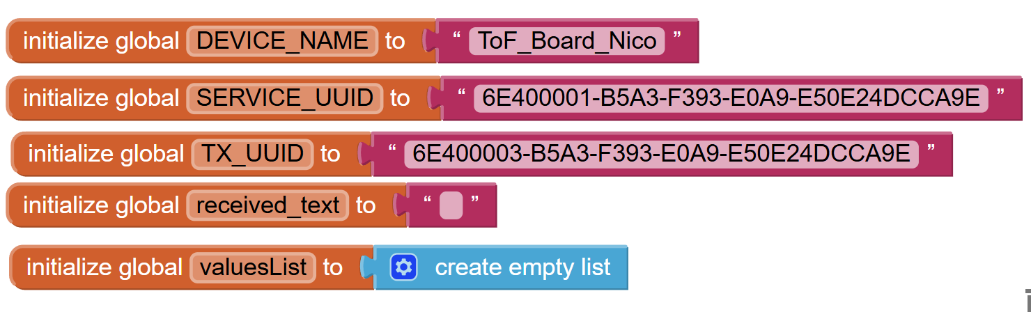
The DEVICE_NAME is the name advertised by the ESP32-C3. The SERVICE_UUID identifies the BLE service, and the TX_UUID identifies the characteristic that sends the sensor values from the ESP32-C3 to the phone.
The variables receivedText and valuesList are used later to process the incoming data packet.
Connect Button
The Connect button starts the BLE connection process. When the user presses the button, the status label changes to connecting…, and the app tries to connect to the ESP32-C3 using the defined device name and service UUID.
when Connect_Button.Click do
    set Status.Text to "Status: connecting..."

    call BluetoothLE1.ConnectToDeviceWithServiceAndName
        serviceUuid = get global SERVICE_UUID
        name = get global DEVICE_NAME
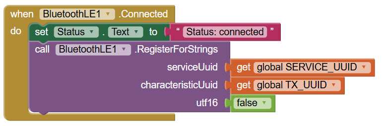
When the connection is successfully established, the BluetoothLE1.Connected event is triggered. The app then changes the status label to connected and registers for incoming string values from the TX characteristic.
when BluetoothLE1.Connected do
    set Status.Text to "Status: connected"

    call BluetoothLE1.RegisterForStrings
        serviceUuid = get global SERVICE_UUID
        characteristicUuid = get global TX_UUID
        utf16 = false

The utf16 option is set to false, because the ESP32-C3 sends a normal text string and not a UTF-16 encoded string.
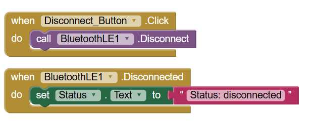
Disconnect Button
The Disconnect button closes the BLE connection manually.
when Disconnect_Button.Click do
    call BluetoothLE1.Disconnect
When the connection is closed, the app updates the status label again.
when BluetoothLE1.Disconnected do
    set Status.Text to "Status: disconnected"
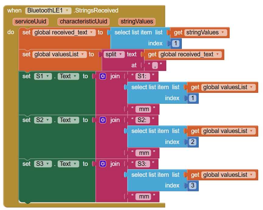
Receiving and Splitting the Sensor Data
The most important part of the app is the StringsReceived block. This block is triggered every time the ESP32-C3 sends a new BLE notification with sensor data.
The app first takes the received string and stores it in receivedText. Then it splits this string at the commas and stores the result in valuesList.
For example, this incoming string:
245,381,129
is split into three list items:
245
381
129
After that, the app writes each list item into the corresponding sensor label.
when BluetoothLE1.StringsReceived serviceUuid characteristicUuid stringValues do

    set global receivedText to
        select list item
            list = get stringValues
            index = 1

    set global valuesList to
        split get global receivedText at ","

    set S1.Text to
        join "S1: "
             select list item get global valuesList index 1
             " mm"

    set S2.Text to
        join "S2: "
             select list item get global valuesList index 2
             " mm"

    set S3.Text to
        join "S3: "
             select list item get global valuesList index 3
             " mm"
This means that the phone display is updated every time a new BLE data packet arrives from the ESP32-C3.
ESP32-C3 code
To make communication between the ESP32-C3 and my mobile app possible, I uploaded a code to the sensor board.
The code initializes three VL53L0X time-of-flight sensors over the I²C bus and assigns each sensor its own address using the XSHUT pins.
This is necessary because all VL53L0X sensors use the same default I²C address when they start up.
After initialization, the ESP continuously reads the distance values from all three sensors.
Each measured value is corrected by a small offset of 14 mm to compensate for the physical sensor position inside the housing.
The code also checks whether the measured distance is inside the useful interaction range between 100 mm and 500 mm.
Valid distances are mapped to a value between 0 and 255, which can later be used for color or brightness control.
For the app connection, the ESP32-C3 creates a BLE server with a custom service and notify characteristic.
Every 300 ms, the current sensor values are sent as a simple comma-separated string, for example 123,240,380, so that the MIT App Inventor app can receive and process them easily.
Testing the App
For the final test, I connected the phone to the ESP32-C3 based ToF board. At first, the connection did not work immediately, because the Android phone still needed the correct Bluetooth and location permissions. After enabling Bluetooth, enabling location, and restarting the app, the BLE connection worked reliably.
Once the app was connected, the ESP32-C3 sent the three ToF sensor values as a comma-separated string. The app received the string, split it into three values, and displayed the live distance readings on the phone.
The final result was a minimal but functional mobile user interface for my own input board.