Final Project
This week’s goal was to complete, document, and present a fully integrated final project, demonstrating the knowledge and skills developed throughout the FabAcademy.
Introduction
At the beginning of week 20, my final project was already in a very advanced state, but there were still many important steps left before the presentation. Most of the design decisions were made, but the project still had to move from separated parts and prototypes into one finished and working system.
Before the presentation, I still needed to do the following steps:
- produce the PCBs
- solder the components with the reflow oven
- do the last hardware store shopping trip
- screw together the mold for the silicone casting
- cast the silicone diffuser
- remove the diffuser from the mold and post-process it
- glue the ash wood parts together
- attach the auxiliary form to the ash wood
- cut and mill the lamp body flush
- develop and print the second version of the 3D printed ToF adapter
- cut new glass plates for the sensor adapter
- mill the groove for the LED strip and the diffuser into the lamp body
- CNC mill the lamp base
- CNC mill the sender unit
- stain the lamp base
- do a short post-processing of the wooden surfaces
- integrate all components
- finish the code
- prepare the final presentation
- edit the final video
- create the PNG slide for the presentation
This week was therefore less about exploring new processes and more about bringing all previous work together. The main challenge was time management, because every unfinished step depended on other steps before it. At the same time, I had to keep the project realistic and focus on the parts that were most important for a working final presentation.
Producing the PCBs
Receiver Unit
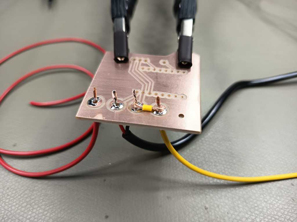
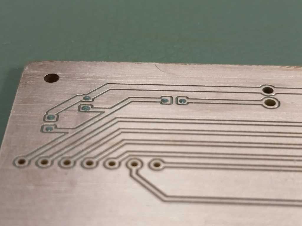
For the receiver unit, the main challenge was the relatively high current of the LED strip. I measured a current of about 3.8 A beforehand, so I did not want this current to flow through the microcontroller or through small PCB traces. Instead, I designed two larger power pads and used a direct bridge with 0.5 mm² wires. The PCB therefore does not act as the main high-current conductor. It mainly provides the control logic and defined connection points, while the high-current path is handled by the external wire bridge.
The receiver PCB itself is quite simple. It carries an ESP32-C3 supermini, which controls the LED strip and the relay.
For switching the power, I used a ready-made relay board that can be controlled directly with a GPIO pin.
For this application, this was the most practical solution, because I had enough space inside the lamp base and did not need to make the switching circuit smaller than necessary.
(relay module - amazon
)
In addition to the relay connection, I routed one GPIO pin to the outside of the PCB for the WS2812B data line. I also added a small series resistor (470 Ohm) into the data line to protect the signal connection and reduce possible signal issues. After producing and soldering the board, I protected the PCB with lacquer. This helps to prevent short circuits, oxidation and problems caused by fingerprints or dirt on the copper traces.
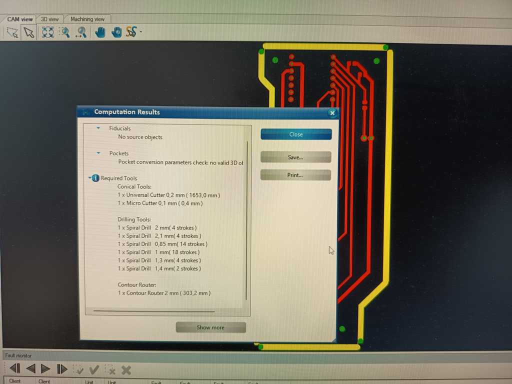
These tools were used:
Sender Unit
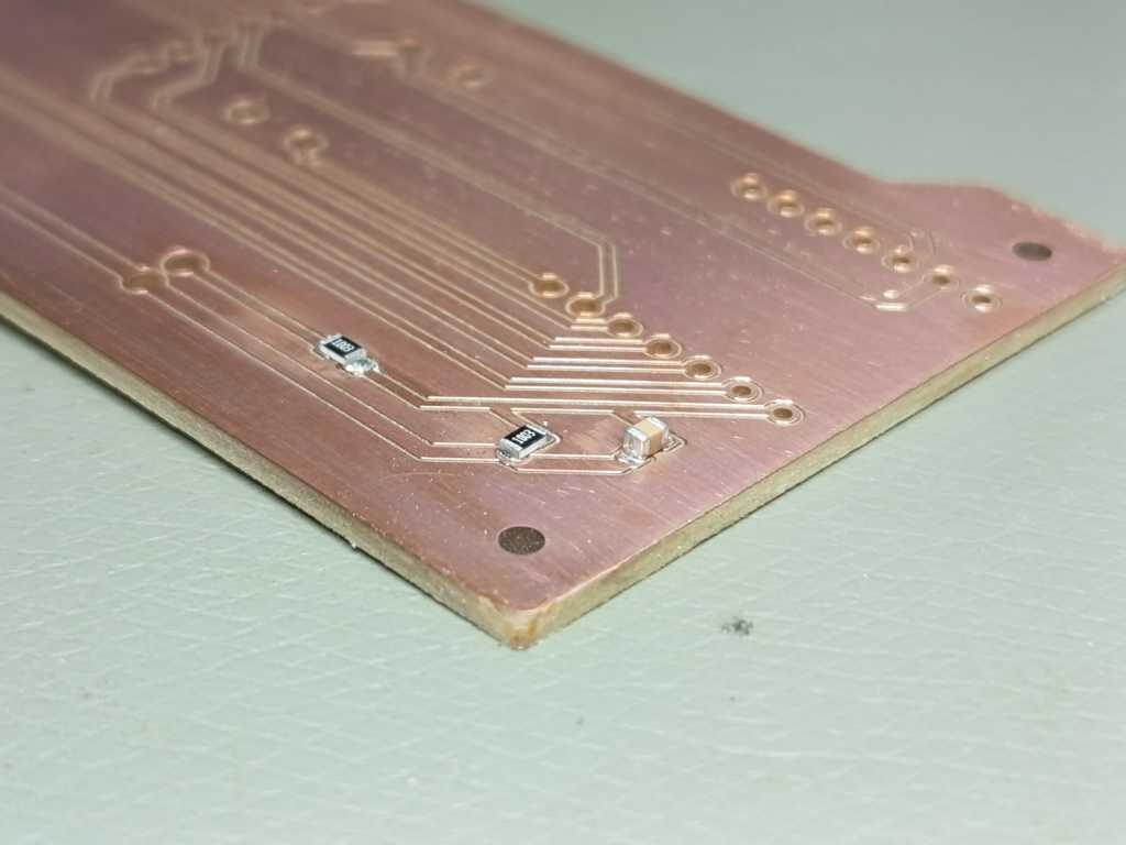
For the sender unit, I reused most of the PCB design from week 9. The basic layout already worked well for my concept, so I only made a few important changes for the final version. The biggest mechanical change was the connector orientation. Instead of using straight female headers, I changed the sensor connections to angled male headers, so the cables and adapters can be connected more cleanly inside the sender housing.
I also added a simple battery measurement circuit to the PCB. For this, I used a small voltage divider with two resistors (100k Ohm) and added a capacitor (0.47 uF) to stabilize the measured signal. This allows the ESP32-C6 to read the battery voltage through an analog input. The rest of the circuit stayed mostly the same and still includes the button, the XSHUT pins for the ToF sensors, the I²C lines, the supply voltage and ground connections.
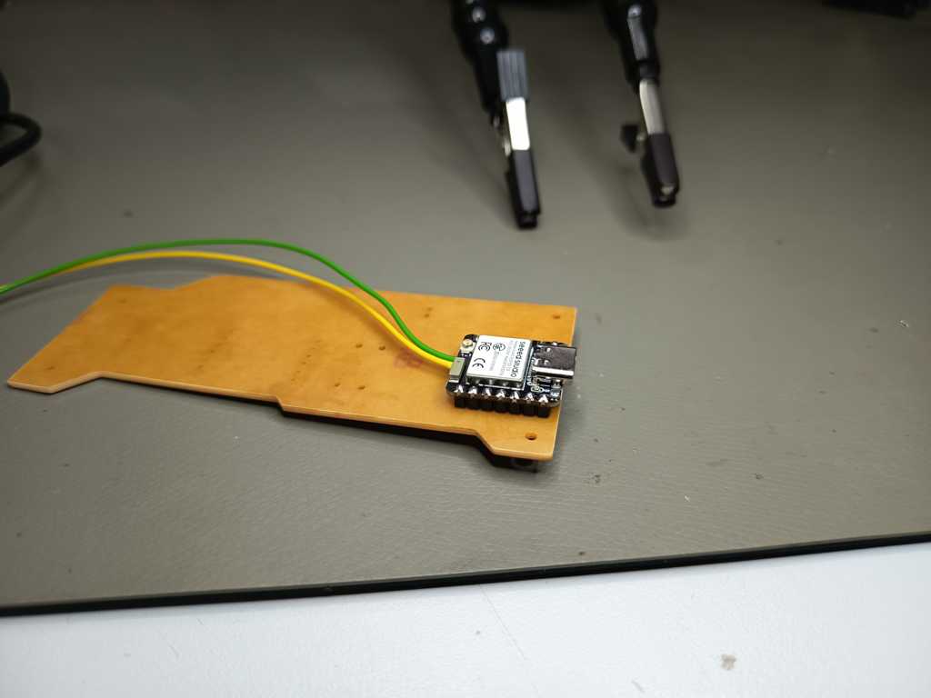
For the microcontroller, I used a XIAO ESP32-C6. This board is useful for the sender unit because it can be powered by a LiPo battery and has battery pads on the back side. The battery can also be charged through the USB-C connector of the board. The LiPo battery itself includes a small protection PCB, which adds a basic safety layer against issues such as overdischarge or overcurrent. This made the sender PCB compact, while still keeping the battery-powered setup practical for the final project.
These tools were used:
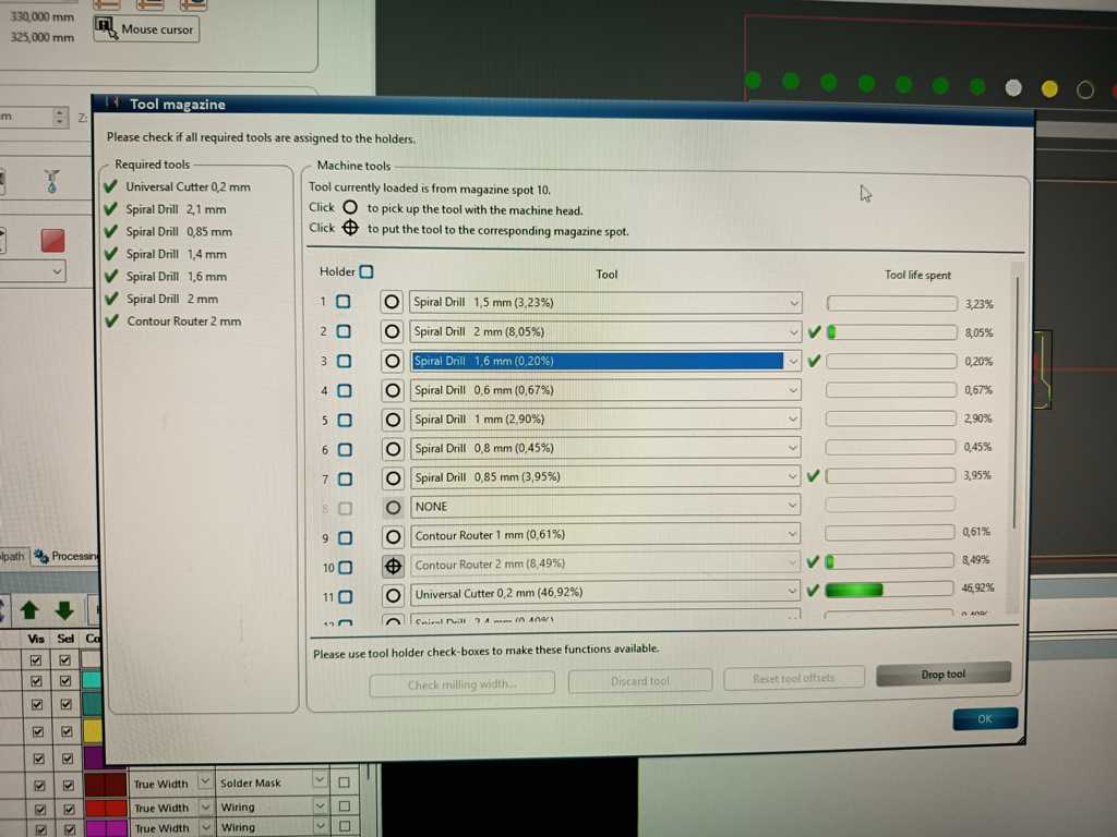
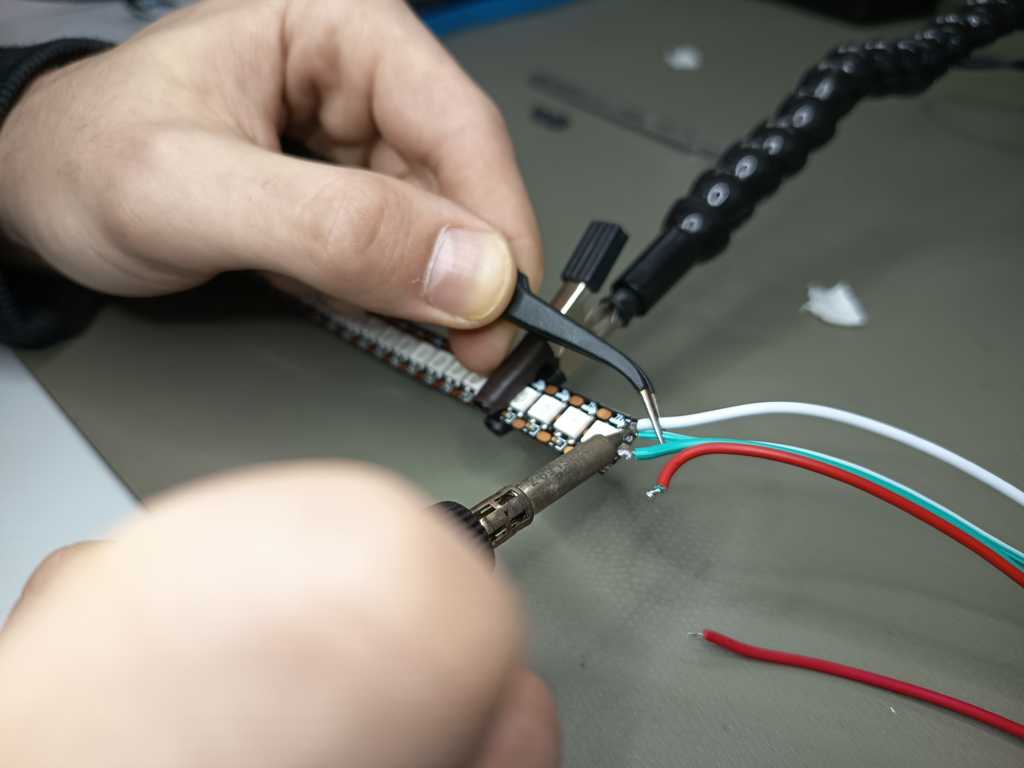
Soldering (with the Reflow Oven)
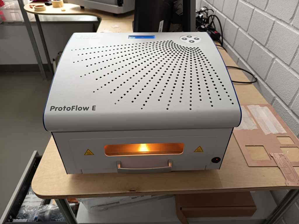
After producing the PCBs, I soldered the SMD components with the reflow oven. For this process, I first applied solder paste to the pads and then placed the components on the PCB. The board is then heated in the reflow oven with a controlled temperature profile.
During the process, the solder paste first dries and then melts. When the solder reaches its melting temperature, it creates the electrical and mechanical connection between the pads and the components. After cooling down, the components are fixed to the PCB and the board can be checked and tested.
After reflow soldering, I visually inspected the solder joints and then continued with the manual soldering of the pin headers and larger connections.
The first blink of the sender unit:
Silicone Casting – Diffuser
The LEDs of the lamp are very bright, and without a diffuser every single LED would be clearly visible. To create a more even and softer light distribution, I decided to make the diffuser myself. I used a simple diffuser geometry with a flat bottom and a rounded half-circle shape on the top side. This shape fits well into the lamp body and gives the light a softer transition.
For the material, I used SF33 RTV-2 silicone. This is a two-component silicone rubber with a milky appearance. It is relatively easy to process and is well suited for casting parts like this diffuser. With careful mixing and vibration, I was able to reduce most of the air bubbles. The curing process can also be influenced slightly by temperature: heat can speed it up, while colder temperatures can slow it down. For my application, the material was a very good choice because it combines flexibility, translucency and simple processing.
I had already prepared the auxiliary mold in the previous week, so I started by screwing the mold together. After that, I built a small setup for the casting process. On the top side of the mold, I added a small tower where I could fix a funnel to pour in the silicone. At the bottom of the mold, I attached an eccentric sander, because the small vibrations help the silicone flow down into the long mold and reduce trapped air bubbles.
After pouring the silicone into the mold, I also carefully used a hammer drill with a chisel attachment to apply slight vibration and movement to the mold. This helped the material to settle further down by about 10 cm and reduced most of the remaining air bubbles. After the silicone had cured, I opened the mold again and could remove the diffuser without any major problems.
Because the inside of the mold had only limited air contact, the silicone was still slightly wet in some areas. I therefore let the diffuser dry for a bit longer after demolding it. Afterwards, I washed it and post-processed a few small spots with sandpaper. Both 400 grit and 320 grit produced a clean result for this step. In the end, I had a clean and usable silicone diffuser for the lamp.
Lamp Body
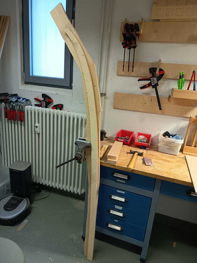
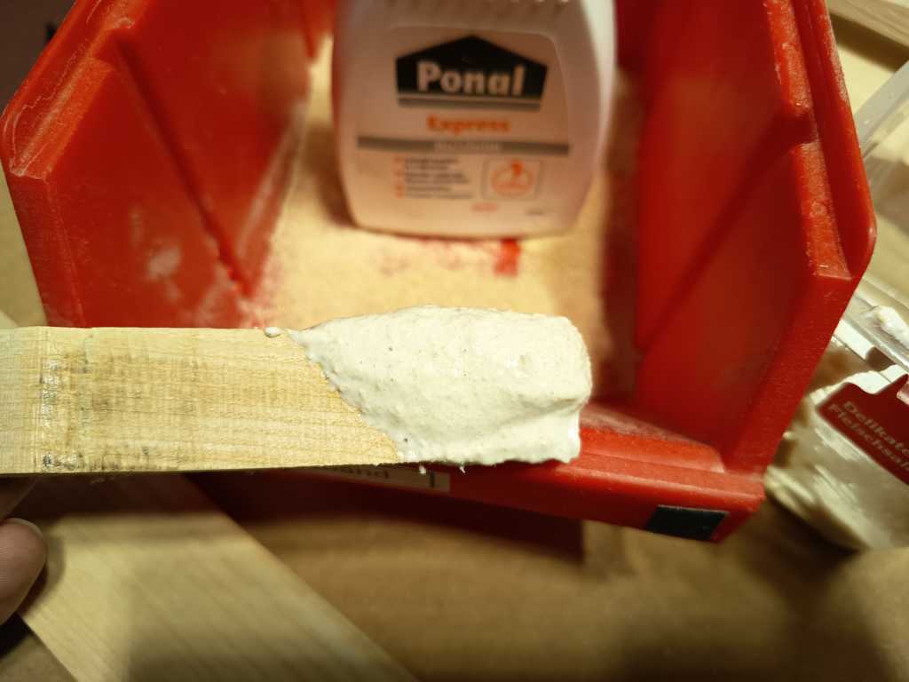
I had already made the auxiliary forms for the lamp body in the previous week, and the ash wood pieces were already roughly cut to size. The next step was to glue the ash pieces together in a way that they could later be attached to the form and shaped with the bandsaw and a flush trim router bit.
For the glue-up, I used two different methods. On the outer sides, I used a fast activator glue to fix the parts quickly. For the inner connection surface, I used normal wood glue and reinforced the joint with a wooden dowel. This was a very useful combination, because the activator glue fixed the pieces within a few seconds, while the wood glue had enough time to cure and create a strong long-term connection. This is a common woodworking approach, but in this case it was especially useful because the glued ash part had to stay stable during the following machining steps.
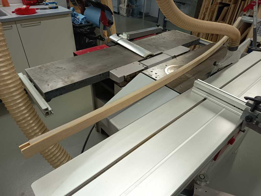
After the glue had dried, I attached the auxiliary forms to the ash wood with double sided tape and a bit activator glue. I then used the bandsaw to cut the wood roughly close to the final shape. After that, I used a router table with a flush trim bit and a ball bearing to copy the shape of the auxiliary form into the wood. I first removed the larger remaining material and then made a cleaner final pass until the ash wood was flush with the form.
When the outer shape was finished, I removed the auxiliary forms again. At this point, the ash wood had the same shape as the form and the basic lamp body was finished.
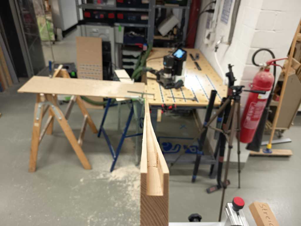
The next challenge was to add the inner groove for the LED strip and the silicone diffuser. Because the groove followed a curved inner contour, I could not simply use a straight fence or a normal router setup.
For this step, I used the Shaper Origin tool and milled it step by step. This was one of the more difficult parts, because the inside of the lamp body has a curved shape and the groove had to follow this geometry cleanly. Instead of trying to mill everything at once, I worked in small sections and slowly created the groove for the LED strip and the diffuser. After this process, the main wooden lamp body was ready for the final integration.
For a few small tear-out spots in the wood, I made my own wood filler. I collected the finest sanding dust and sawdust from the previous machining steps and mixed it with wood glue. This created a simple filler paste that matched the ash wood quite well and could be used to fill and repair small imperfections in the lamp body.
Lamp Base
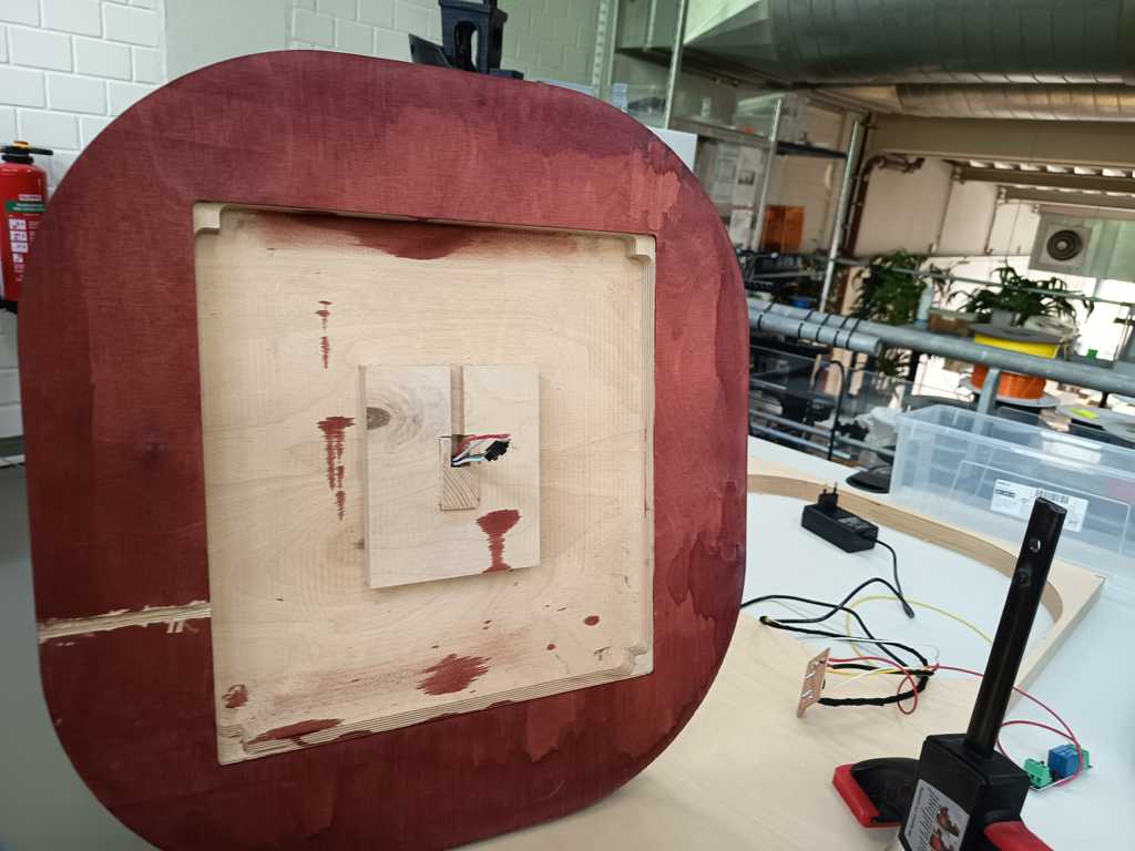
For the lamp base, I reused the general design from my prototype. I only adjusted the inner cutout for the final lamp body, so the wooden body fits into the base in a press-fit style. This gives the connection enough stability and also allows me to glue it in place later.
On the bottom side of the base, I added a large pocket for the electronics and wiring. The larger pocket also avoids a very tight installation and gives the electronics and wiring more free space inside the base.
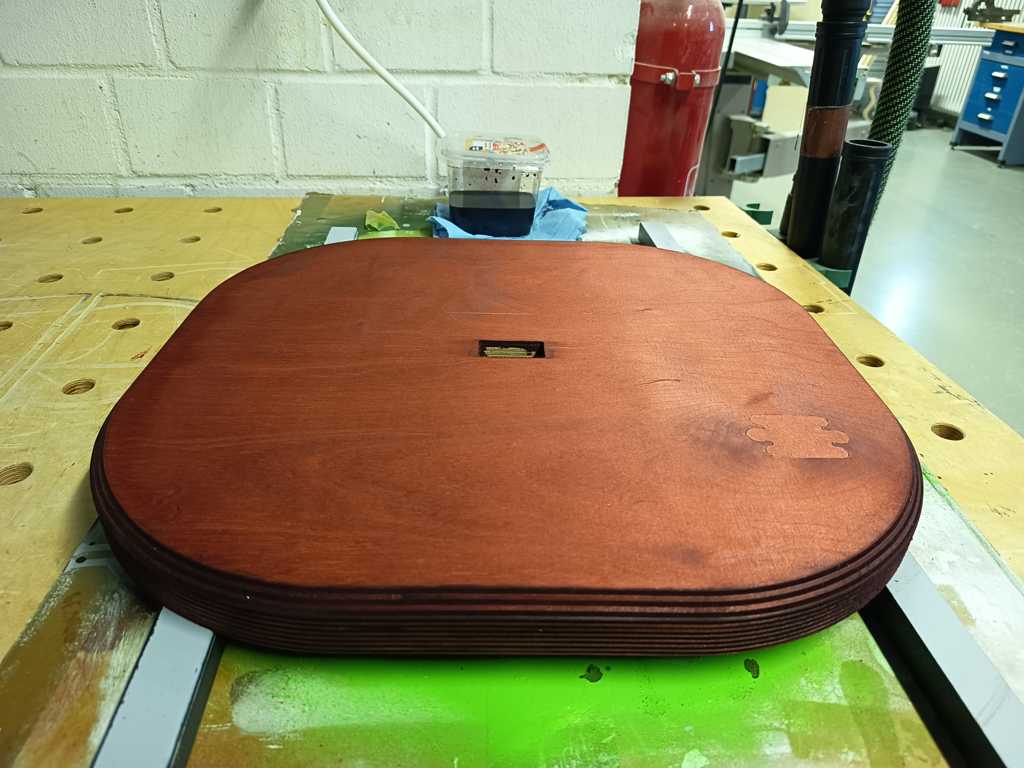
I manufactured the base on the CNC milling machine and then post-processed it by hand. After milling, I cleaned the surface and rounded the edges with the router table. Afterwards, I stained the base with mahogany stain. I used a larger amount of stain on the end grain sides, because I wanted these areas to become significantly darker and create a stronger visual contrast.
During the final check, I noticed that I had forgotten the slot for the power cable. Since the base was already milled, I added this slot manually afterwards with a chisel and a Dremel. After this correction and a short final post-processing step, the lamp base was ready for the integration.
Sender Unit
I produced the sender unit from a second piece of ash wood. For this part, I used the CNC milling machine to mill the complete shape and the inner pockets directly into the wood. The machining process worked well and gave me a clean wooden housing for the electronics.
The sender unit includes three openings for the ToF sensors, a larger pocket for the wiring and some additional space on one side for the PCB. This layout gives the sensors a defined position and still leaves enough room inside the housing to connect the electronics.
After milling the part, I realised the ash wood and the smaller openings seemed to create more internal reflections or optical interference than the prototype. Because of that, I enlarged the openings slightly afterwards to improve the optical conditions for the ToF sensors. After this adjustment, the basic wooden sender housing was ready for the final integration.
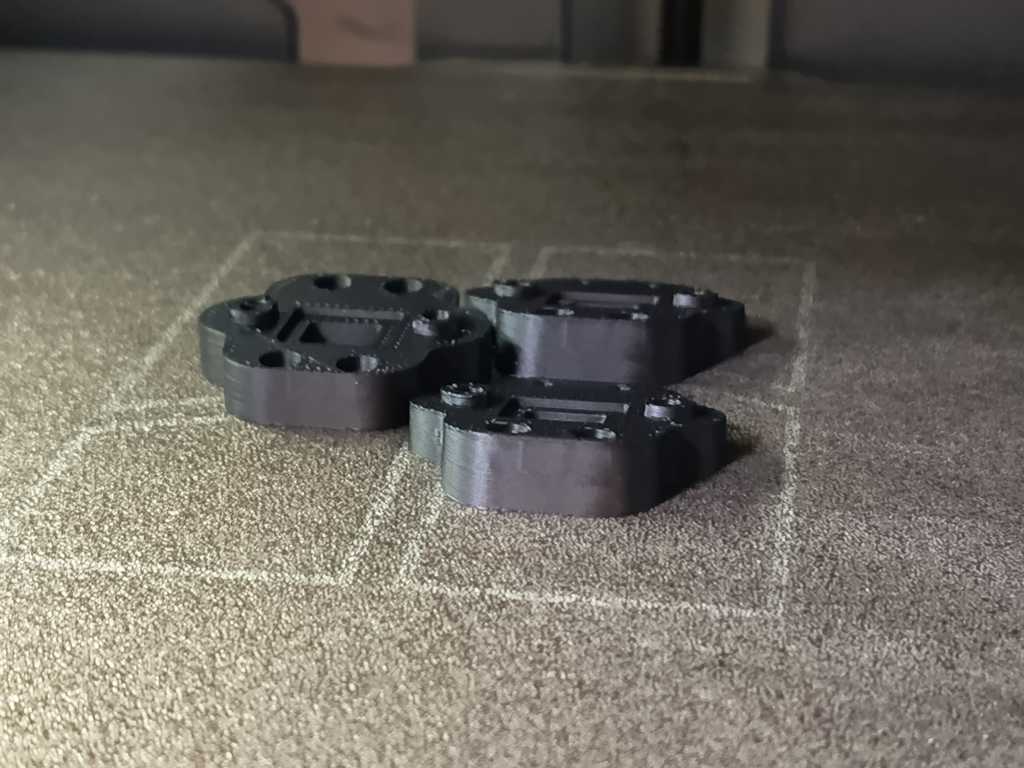
I also redesigned the 3D printed adapters for the ToF sensors. During testing in the last week, I noticed that the previous opening was slightly too small and influenced the sensor readings. In the new version, the small glass plate is placed directly in front of the ToF sensor and is later glued into the outside of the adapter.
The new opening is also significantly larger than before. With this construction, the sensor has a clearer optical path and I can expect more reliable distance measurements during the final integration.
Integration
Lamp
For the lamp integration, I first inserted the WS2812B LED strip into the inner groove of the lamp body. The LED strip is about 12.2 mm wide, while the groove is 12 mm wide, so the fit was already quite tight. This was not a major problem, because the outer edges of the LED strip can bend slightly without damaging the strip. To make sure that it stays in place, I additionally fixed it with gel superglue.
After the LED strip was installed, I glued in the silicone diffuser. For this step, I used the same gel glue again. At the top end of the lamp body, I cut the silicone diffuser manually with a cutter knife and inserted the final small piece afterwards, so the transition looked as seamless as possible.
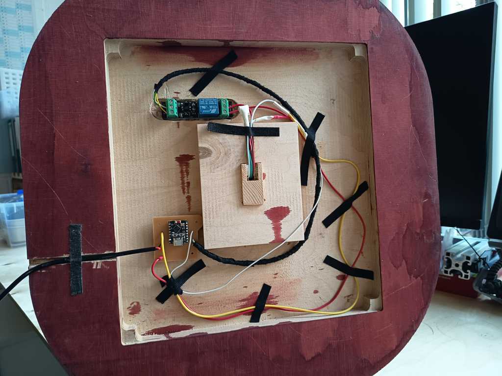
Then I prepared the lamp base with wood glue and inserted the lamp body into the press-fit opening. I removed the excess glue and started placing the electronic components inside the base. For the PCBs, I used hook-and-loop tape. The tape can be glued to the wood with activator glue, while the adhesive side sticks well to the PCBs. I also added a small drop of superglue for extra security. With this solution, the PCBs can still be removed and attached again if I need to access them later.
For the wiring, I wrapped the cables with flame-retardant insulation tape. The black tape makes the inside look cleaner, helps to guide the cables and also allows me to fix them in specific positions. To make sure the tape holds properly on the wood, I used a small amount of activator glue again. After everything was connected, I tested the lamp directly. The test worked without problems, and I was able to run my color gradient on the LED strip.
Sender Unit
For the integration of the sender unit, I first installed threaded inserts into the 3D printed ToF sensor adapters. I melted the inserts carefully into the printed parts, so the ToF sensors could later be mounted securely with screws. After that, I glued the small glass plates into the adapters. The glass plates sit directly in front of the ToF sensors and protect them from the outside, while still allowing the sensors to measure through the opening.
After preparing the adapters, I placed them very accurately over the sensor openings in the wooden sender housing and marked their final position. I then fixed them with the two-component activator superglue system. I also used the same black insulation tape again, which was very practical for guiding and securing smaller parts and cables inside the housing.
Inside the sender unit, I placed the battery in the middle and the PCB on one side. I used jumper cables for the connections and reinforced the connector areas with insulation tape, so the cables cannot come loose too easily during handling. After all components were installed, I tested the sender unit directly. The first test worked very well.
Finally, I added a small laser-cut cover on top of the electronics area. This keeps the cables in place and prevents loose wires from moving around inside the sender unit. After this step, the sender unit was fully integrated and ready for the final system test.
Coding
For the programming of the final project, I used Codex again. I first sketched the required functions and the intended behavior of the system. After that, I developed a more precise prompt with ChatGPT and sent this prompt to Codex. This workflow helped me to translate my technical concept into a working Arduino code structure more quickly.
Due to the limited time before the final presentation, I decided to implement only one operating mode for the final version. This mode is the direct or fast mode. In this mode, the sender reads the current sensor values and directly transmits the resulting RGB values to the lamp without an additional confirmation step. Originally, I planned to implement more interaction modes with storing and confirming values, but for the first integrated version this direct mode was sufficient. It can react a bit more sensitively to sensor noise or small hand movements, but it already demonstrates the main function of the project: contactless color control through the separate sender unit.
Sender Code
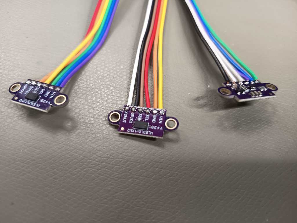
The sender code runs on the XIAO ESP32-C6 and is responsible for reading the three VL53L0X Time-of-Flight sensors, measuring the battery voltage and transmitting the color values to the receiver via BLE.
At the beginning of the code, the pins for the three XSHUT lines, the I²C bus, the button and the battery measurement are defined. The three VL53L0X sensors all use the same I²C address by default, so they cannot simply be connected to the same bus without additional handling. For this reason, the code uses the XSHUT pins to activate the sensors one after another and assign them individual I²C addresses. After initialization, the sensors run in continuous measurement mode.
The measured distances are then converted into color values. Each sensor has its own zero point, because the mechanical setup and the sensor positions are not exactly identical. If a measured distance is below the defined zero point, the value is mapped to 0. If the distance is within the valid range up to 500 mm, it is mapped to a color value between 0 and 200. If the sensor value is invalid or out of range, the code sends -1 for this channel.
In the final mapping, the physical sensor order is converted into the logical RGB order. Physical sensor 1 controls red, physical sensor 3 controls green and physical sensor 2 controls blue. This correction was necessary because the mechanical sensor order and the intended color order were not identical.
The sender also measures the battery voltage through the voltage divider on the PCB. To make this value more stable, the code takes several ADC samples and calculates an average. The measured battery voltage is then added to the BLE message.
Every second, the sender creates a payload in this format:
R=...;G=...;B=...;BAT=...
This payload is sent to the receiver through a writable BLE characteristic. The code also includes a reconnect mechanism. If the sender is not connected to the receiver, it scans for the BLE service again and tries to reconnect automatically.
The button is already read in the code and printed to the serial monitor, but in this version it is not used for changing modes yet. This leaves the structure open for later extensions, while keeping the final presentation version simple and reliable enough.
Receiver Code
The receiver code runs on the ESP32-C3 inside the lamp base. It receives the RGB values from the sender via BLE and controls the WS2812B LED strip with the FastLED library.
The receiver defines the LED data pin, the number of LEDs and the LED type. In my final lamp, the LED strip contains 236 WS2812B LEDs and is connected to GPIO10. The relay is controlled through GPIO7. The maximum brightness value is limited to 200, so the LEDs are not driven at full 255 brightness.
The ESP32-C3 starts a BLE server and advertises a custom BLE service. Inside this service, it creates a writable characteristic. The sender writes the RGB payload into this characteristic. When new data arrives, the receiver parses the fields for R, G, B and BAT.
The receiver also checks the received values before applying them. If a value is missing, negative or above the defined maximum value, it is set to 0. This is important because the sender uses -1 for invalid or out-of-range sensor readings. On the receiver side, this means that an invalid channel is safely turned off instead of creating an undefined LED output.
After parsing the values, the receiver applies the RGB color to the complete LED strip. The code uses fill_solid() to set all LEDs to the same color and then updates the strip with FastLED.show(). This creates one uniform lamp color based on the current hand position above the sender unit.
The relay is linked to the current RGB output. If all three color channels are 0, the relay is switched off. As soon as at least one channel has a value above 0, the relay is switched on. This means the lamp power is automatically disabled when the transmitted color is black.
The receiver updates the LED output every 500 ms. This is fast enough for a visible response, but still keeps the behavior controlled and avoids unnecessary updates. The serial monitor also prints the received payload, the parsed RGB values and the relay state, which made testing and debugging much easier.
Result
With this first integrated code version, the complete signal chain works: the sender reads the ToF sensors, maps the distances to RGB values, sends them via BLE and the receiver displays the color on the LED strip. The direct mode is not the final interaction concept with all planned features, but it is a functional and understandable first version of the complete system.
Bill of Materials
The following table gives an overview of the main components and materials used for FlowLi. Some parts were bought specifically for the project, while others were already available in the FabLab or from my own stock.
| Part / Material | Quantity | Source | Stock / Bought | Approx. Cost | Notes | Link |
|---|---|---|---|---|---|---|
| ESP32-C3 SuperMini | 1 | FabLab stock | FabLab stock | 2 € | Used as receiver microcontroller | AliExpress |
| Seeed Studio XIAO ESP32-C6 | 1 | Reichelt | Bought | 7 € | Used as sender microcontroller | Reichelt |
| VL53L0X Time-of-Flight sensor | 3 | Amazon | Bought | 21 € total | Used for contactless hand distance measurement | Amazon |
| WS2812B LED strip, 1 m, 144 LEDs/m | 2 | Amazon | Bought | approx. 30 € total | Two LED strips were used for the lamp illumination | Amazon |
| 3.3 V relay module | 1 | Amazon | Bought | 4 € | Only one relay module was used, although the product was sold as a set of two | Amazon |
| FR4 copper clad board, single-sided, 19 µm | 2 pieces | FabLab stock | FabLab stock | approx. 5 € | Used for the sender and receiver PCBs | Amazon |
| SMD resistor, 100 kΩ | 2 | FabLab stock | FabLab stock | available stock | Used for the battery voltage divider | Reichelt |
| SMD capacitor, 0.47 µF | 1 | FabLab stock | FabLab stock | available stock | Used for the battery voltage divider | Reichelt |
| Button | 1 | FabLab stock | FabLab stock | available stock | Used for the sender unit | TobyElectronic |
| SF33 RTV-2 silicone, 0.5 l + 0.5 l | 1 set | Silikonfabrik | Bought | 43.75 € | Used for casting the LED diffuser | Silikonfabrik |
| Multiplex plywood | 1 piece | FabLab stock | FabLab stock | available stock | Used for the lamp base | HolzLand Hegener |
| Wood stain | small amount | Hardware store | Bought | 1 € | Bought on sale and used for the base finish | Hornbach |
| Ash wood board | 2 | Hardware store | Bought | 40 € total | Used for the wooden lamp body and sender unit | Hornbach |
| 3D printing filament | small amount | FabLab stock | FabLab stock | available stock | Used for the sender housing and smaller printed parts | BambuLabStore |
| Microscope glass slide | 1 | Own stock | Own stock | available stock | Used as sensor cover material | Laborshop24 |
| 5 V power supply | 1 | AliExpress | Bought | 8 € | Used to power the LED system | AliExpress |
| 3.7 V 3450 mAh LiPo Battery | 1 | DigiKey | Bought | approx. 20 € | Used to power the sender unit | DigiKey |
| Wood glue | small amount | FabLab stock | FabLab stock | available stock | Used for gluing the ash wood parts of the lamp body | Hornbach |
| 2K activator glue | small amount | Hardware store | Bought | 10 € | Used for fast fixing and assembly during the final integration | Hornbach |
| Screws, finishing materials, wires and pin headers | several | FabLab stock | FabLab stock | available stock | Used for assembly, wiring and finishing | - |
| Flame-retardant insulation tape | small amount | Own stock | Own stock | available stock | Used for electrical insulation inside the lamp | AliExpress |
Estimated direct project cost: approx. 172 €, depending on the exact prices of the LED strips, microcontroller boards, sensors and the amount of ash wood used.
Many small parts, such as resistors, wires, pin headers, screws, glue and finishing materials, were already available in the FabLab. Therefore, the real cost of rebuilding the project from scratch would be slightly higher than the direct project cost shown here.
Packaging
For packaging the lamp, I would use a large cardboard box with enough padding inside to keep the product fixed during transport. The lamp itself is not extremely fragile, because the main components are integrated quite firmly into the wooden body and the base. Still, the packaging should prevent the lamp from moving around inside the box and protect the surface of the wood from scratches or pressure marks.
For version 1, I did not have enough time to design the lamp body and the lamp base as two separate detachable parts. This means that the complete lamp has to be shipped as one larger object. For a second version, I would improve this by making the lamp body removable from the base. The LED strip could then be connected with a proper plug connector, while the rest of the electronics would stay inside the lamp base. This would make the packaging smaller, cleaner and easier to handle.
The sender unit would be packed in a separate smaller cardboard box with light padding. Since it is already fully assembled, the user would not need to build anything before using it. For a future version, I would also improve the battery integration. Ideally, the battery could either be removed and shipped separately, or it could be disconnected during transport with a small battery isolation tab. This would prevent the unit from slowly discharging before it reaches the user.
Overall, both parts should be packed in appropriate cardboard boxes with simple but effective padding. For the current version, the packaging would mainly focus on protecting the wooden surfaces, keeping the electronics fixed and making sure that the lamp and sender unit arrive in a clean and usable condition.
License and Use
FlowLi is published under a Creative Commons Attribution-NonCommercial-ShareAlike license (CC BY-NC-SA).

Other students, makers and FabLab users may use the project as inspiration, rebuild parts of it or develop similar systems based on the documentation, as long as the use stays non-commercial, attribution is given and adapted versions are shared under the same license.
Commercial use is not allowed without my permission. This is important to me because the product design, the interaction concept, the system architecture, the project identity and the name FlowLi are part of my own development. If parts of the project are reused, my name and the project name FlowLi should stay connected to the original work.
FlowLi uses existing components and technologies, such as ESP32 microcontrollers, VL53L0X Time-of-Flight sensors, BLE communication, WS2812B LEDs and open-source Arduino libraries. These components and libraries are not my own invention. My own contribution is the way I combined them into one complete interactive lighting system, including the wooden lamp body, the sender unit, the custom PCB design, the firmware, the silicone diffuser, the mechanical integration and the final project identity.
I also used ChatGPT and Codex during the project. I used ChatGPT mainly to structure ideas, improve documentation text, develop prompts and reflect technical decisions. I used Codex as support for writing and improving parts of the Arduino code. The final decisions, testing, integration, debugging and documentation were still done by me.
Presentation
For the final presentation, made a one-minute video and a summary slide as a PNG file. I edited the video in DaVinci Resolve and used Canva to create the final presentation slide. The goal was to show the concept, the main fabrication steps and the final function of the lamp in a clear and compact format.
Final Reflection
FlowLi was a very ambitious final project. It was not only one isolated object, but a complete system consisting of mechanical design, furniture making, electronics production, embedded programming, sensor integration, wireless communication, casting, lighting and final assembly. Many of these steps depended strongly on each other. A small delay or problem in one part of the project directly influenced the next steps.
During the last weeks, I worked roughly 10 to 14 hours per day on the project. I invested a lot of time, energy and focus into bringing the system as close as possible to my original idea. In the end, I am very happy with the result. FlowLi became a functional and visually strong final project, and it shows the main idea very clearly: a contactless control unit that communicates wirelessly with a standing lamp.
At the same time, not every detail became as perfect as I originally hoped. During the milling of the wooden lamp body, the bearing of the flush trim router bit came loose. Because of this, the router cut slightly into the side of the lamp body. I was able to repair the affected area quite well, but small traces are still visible. There were also a few small tear-outs in the wood, which I could mostly fix during sanding and finishing.
The silicone diffuser also works well, but it is not perfectly integrated everywhere. In some areas it sits slightly deeper than in others. This does not destroy the overall appearance of the lamp, but it is one of the details I would refine in a next version.
Another small design issue is the cable routing. Because I was under a lot of time pressure during the final body design, I forgot to include a clean groove or recess for the power cable in the lamp body. The cable solution works, but visually it is not as clean as I would like it to be.
I also lost a lot of time during electronics production. The setup of the LPKF PCB milling machine was not optimal at the beginning, and because of that I had to mill some PCBs again. This cost several hours and made the final phase much more stressful. Still, I was able to solve these problems, keep the workflow consistent and continue with the next production steps.
The final phase was very tight. I finished the project only about one hour before the final deadline, which made the video editing and final documentation much more stressful than planned. Looking back, I should have reduced the scope a little earlier. I spent a lot of time on refinements and additional details, while some software functions could have been prepared earlier.
Nevertheless, I think the final result worked out very well. The lamp, the sender unit, the electronics and the communication system came together into one complete project. Even with some small imperfections, FlowLi feels like a real object and not only like a technical prototype.
| Part | Result | Notes |
|---|---|---|
| BLE communication | Worked | Sender and receiver exchanged RGB values reliably during the final test. |
| LED output | Worked | The receiver displayed the transmitted values on the WS2812B strip. |
| Relay control | Worked | The relay switches off when all RGB values are zero. |
| ToF interaction | Partly worked | The direct mode works, but the sensor values are still sensitive to hand movement and optical conditions. |
| Interaction modes | Not fully implemented | I focused on one direct mode due to time limitations. |
| Mechanical integration | Worked | Lamp body, diffuser, electronics and sender unit were integrated into one physical system. |
I would also like to thank the FabLab Bottrop team, my instructors and the other FabAcademy students for their support, feedback and help during the development of the project. Their input was especially helpful during electronics production, debugging, system integration and the final phase of the project.
Open Tasks after FabAcademy
After FabAcademy, I would like to continue improving FlowLi. The most important next step is the software. For the final presentation, I focused on one direct control mode because it was the safest and most realistic option within the remaining time. In a next version, I want to extend the code and integrate the additional modes that I originally planned.
I would also like to add a DJ mode with stronger dynamic light behavior, including strobe effects and more performance-oriented animations. A larger future idea is the connection to DJ software such as Rekordbox. As already mentioned in Week 19, Rekordbox can analyze musical phrases and track structure. This information could be used to control the light behavior automatically and make FlowLi react not only to hand gestures, but also to music.
The sender unit also needs further refinement. The current version works as a prototype, but I did not manage to fully integrate the button before the deadline. I originally planned to make a small turned wooden button for the sender. This would improve both the function and the visual connection between the sender unit and the wooden lamp body.
For a next version, I would also improve the sensor integration, the sender housing and the cable routing. The goal would be to make the whole system more reliable, cleaner and closer to a finished product.
Overall, I am very satisfied with FlowLi. The project was stressful, complex and very time-consuming, but it also brought together many of the skills I learned during FabAcademy. It gave me a much better understanding of how difficult system integration can be when design, electronics, software and fabrication all have to work together in one physical object.
FAQ
What does it do?
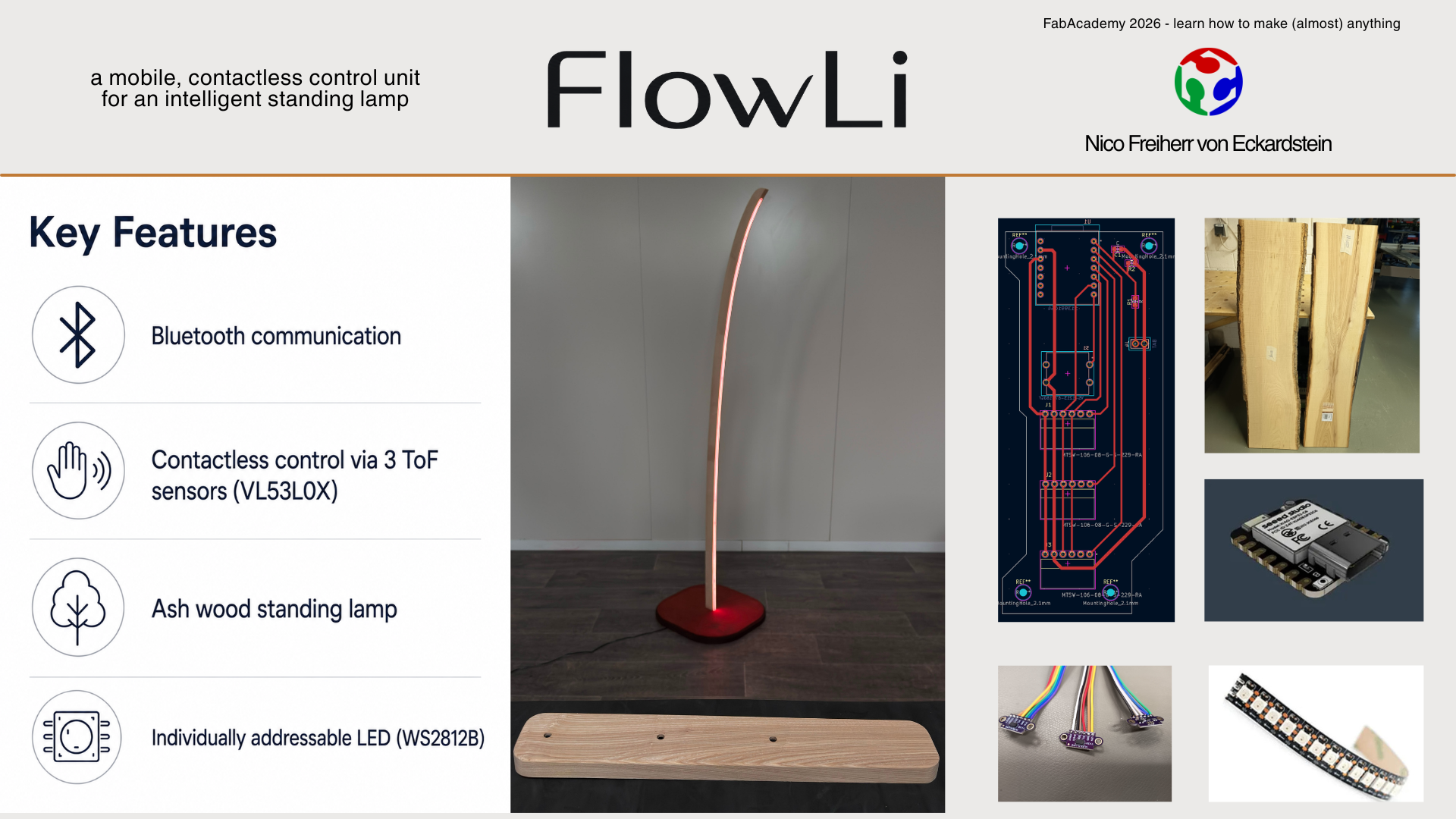
FlowLi is a standing lamp that can be controlled without touching it. It has a separate small control unit. When I move my hand over this unit, the color of the lamp changes wirelessly.
Who’s done what beforehand?
There are already many smart lamps and lamps that can change color. There are also many projects that use sensors or wireless control. My project combines these ideas into one handmade object: a wooden standing lamp with a separate contactless control unit.
What did you design?
I designed the lamp, the control unit, the wooden housings, the electronics layout, the light diffuser and the way the user interacts with the lamp.
What sources did you use?
I used my previous Fab Academy assignments, datasheets, examples from Arduino libraries, online documentation and support from ChatGPT and Codex during planning, writing and coding.
What materials and components were used?
I used ash wood, multiplex, silicone, small glass plates, 3D printed parts, circuit boards, LEDs, microcontrollers, sensors, a battery, cables, glue and stain.
Where did they come from?
Some materials came from the FabLab stock. Other parts were bought online or from local hardware stores.
How much did they cost?
The total material cost of FlowLi was about 172 €. The exact costs are listed in the Bill of Materials. The most expensive parts were the LED strip, the silicone, the sensors, the microcontrollers and the wood.
What parts and systems were made?
I made the wooden lamp body, the lamp base, the control unit, the silicone light diffuser, the sensor adapters and the custom circuit boards. I also built the complete electronic system and programmed the lamp control.
What processes were used?
I used CNC milling, waterjet cutting, laser cutting, circuit board milling, soldering, 3D printing, silicone casting, woodworking, sanding, staining, electronics integration, programming and video editing.
What questions were answered?
The project answered several important questions during the final integration. The sensor concept worked and could be used to control the lamp without touching it. The sender and receiver exchanged color values wirelessly during the final test, and the lamp displayed these values on the LED strip. The relay control also worked and switches the lamp off when all color values are zero.
The mechanical integration was also one of the main questions. It was not completely clear beforehand if the wooden body, the silicone diffuser, the LED strip, the electronics and the sender unit would all fit together in one working physical system. The production was challenging, especially because many parts depended on each other, but in the end the main concept and the integration worked.
What worked? What didn’t?
The lamp body, the light diffuser, the electronics, the wireless connection and the basic color control worked. The direct control mode was sufficient for the final presentation and showed the main interaction concept clearly.
Some parts were more difficult than expected. The sensor interaction partly worked, but the values are still sensitive to hand movement and optical conditions. I also did not have enough time to implement all planned interaction modes. For the final version, I focused on one direct mode instead of several more advanced modes.
How was it evaluated?
I evaluated the project through an iterative development process. I did not test only the final product, but checked the system step by step while adding more functions. First, I tested individual components such as the LEDs, the PCBs, the sensor readings and the power switching. After that, I tested the sender unit and the receiver unit separately.
In the final phase, I tested the complete system as one integrated product. The important evaluation point was whether the sender could read the hand interaction, transmit the values wirelessly and control the lamp output reliably enough for the final demonstration. This final system test showed that the concept works.
What are the implications?
FlowLi is now a functional first version of an interactive lighting product. It proves that the basic concept works: a separate contactless sender unit can control a standing lamp wirelessly and create a different kind of interaction with light.
This gives me a strong foundation for the next development step. In a second version, I would improve the sender unit, polish the product design further, refine the sensor behavior and improve the battery integration. I would also extend the code with more interaction modes, so the lamp can react in more flexible and expressive ways. The current version is therefore not only a final Fab Academy project, but also a working starting point for a more refined product.
Downloads
lamp - KICAD
sender - KICAD
lamp - GERBER
sender - GERBER
lamp - Fusion
lamp - STL
sender - Fusion
sender - STL
adapter - Fusion
adapter - STL
sender code - ino
receiver code - ino