07. Computer-Controlled Machining (Make Something Big)
view Idea Checklist
- organic table legs with TOP structure, based on FEM
- folding box with maximum rigidity for laundry
- laundry storage boxes
- cloth hangers for the wall
- folding flat to the wall when not used
- exposing mdf structure by chamfering the edges
- multiplex chair, layers
- multiplex topography map, Thüringen
- multiplex super thin 3D bodies, semi transparent for light
view Checklist from Nueval
- Linked to the group assignment page
- Reflected on your individual page what you learned of your labs safety training
- Documented how you designed your object and made your CAM-toolpath
- Documented how you milled and assembled your final product (including setting up the machine, fixturing, feeds, speeds etc.)
- Described problems and how you fixed them
- Included your design files and 'hero shot' of your final product
Group Assignment
The Group Assignment can be found here.
Scope of the Project
The scope of the project was re-design our Laser cutter and 3D printing room with new custom furniture and a build in fume exhaust system to improve the occupational safety. The requirements for the new 3D printer cabinet are:
- resin compartment with exhaust
- printer/washing station/curing station
- UV light to cure the working area after use
- storage for resin equipment
- FDM compartment for
- 2x Prusa Core Ones
- Voron
- storage for filaments
Modeling the Room in Fusion
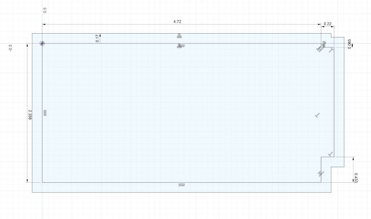
For the room measurement I used the Bosch Zamo laser measure. For every distance I measured I took tree values to make sure every measurement is correct. Before I modeled everything in Fusion, I made a simple sketch on my tablet, while measuring. I measured different length from the same starting point to avoid adding up errors. I took all the measurements at approximately 2.2 m height, since at that height the exhaust tubes will be placed.
First I transferred my hand drawn sketch to Fusion 360 as a floor plan to extrude the walls.
Adding Machines
Prusa Printers:
Laser cutter:
- CO2 80W Laser cutter
- xTool F2 Ultra UV
For the Laser cutters I just did a quick mockup in Shapr3D which I have already used in Week 02 - Computer-Aided Design. With Shapr3D it is very easy and quick to 'model on the go' when not being located at my desk. This saves the time of creating a sketch while measuring, therefore the model can be created directly.
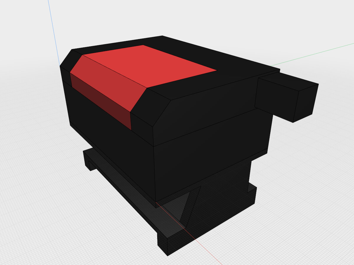
Mockup of the CO2 laser in our lab. Created with Shapr3D
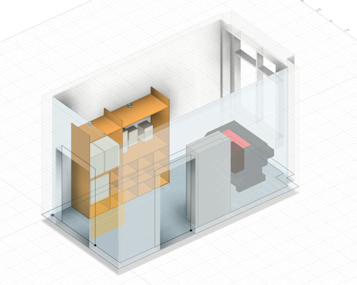
Laser cutter and 3D printer room with equipment and Benedikts design of the printer cabinet.
General Information on Woodworking
The printer cabinet project was started by Benedikt from our lab. After many issues with our current SLA setup we decided to start form scratch and redesign the cabinet for 18 mm Multiplex plywood and Festool Domino Fasteners.
Characterization of the Material
In our lab we all got a large piece of plywood, in this case Multiplex which is a multi-layered plywood material. Multiplex is known for its very good structural integrity and multi-directional load capacity. The downside of Multiplex is its high density which makes it very heavy.
Measuring the existing Material
Our multiplex sheet is 1250 mm * 2500 mm with a thickness of 18 mm. Ferdi recommended to us before we start with any work to measure the thickness variation of our sheets. Jakob and I started to compare the thickness of the material on different spots of the material. Every measurement point was about 30 cm apart and can be seen in the picture below.
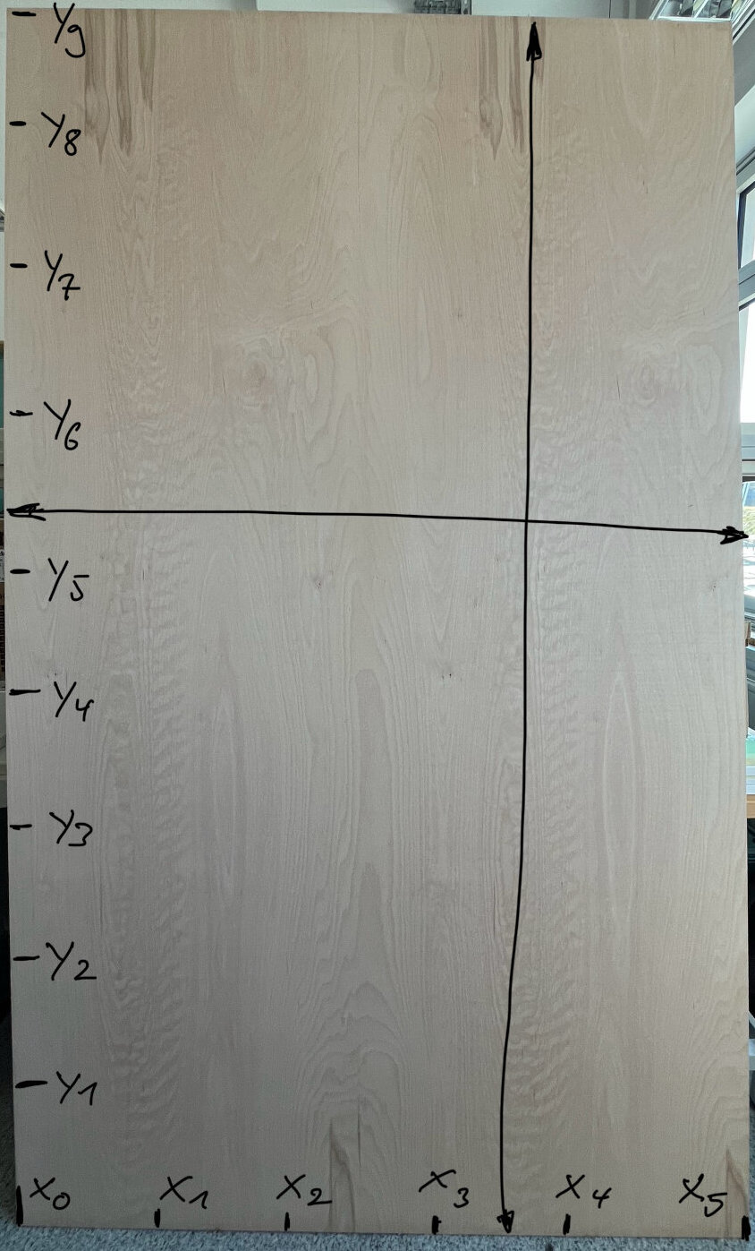
My Multiplex sheet that will be used for the printer cabinet. Every sheet is different therefore an individual characterization is useful. Measurement positions are marked with x0 to x6 and y1 to y8.
These are the results of the measurements for my multiplex sheet.
| Position: | x0 | x1 | x2 | x3 | x4 | x5 | x6 | y1 | y2 | y3 | y4 | y5 | y6 | y7 | y8 |
|---|---|---|---|---|---|---|---|---|---|---|---|---|---|---|---|
| Value: | 18,10 | 18,18 | 18,10 | 18,25 | 18,17 | 18,11 | 17,10 | 18,11 | 18,27 | 18,01 | 18,05 | 18,10 | 18,00 | 18,01 | 17,99 |
| Parameter | Value |
|---|---|
| avarage: | 18,04 |
| minimum: | 17,10 |
| maximum: | 18,27 |
As Ferdi had already predicted, the difference in thickness is very large. Thus, we decided to mill a comb to determine the optimum plug fit for Multiplex
Comb for plug fit
- parametric design
- chamfer for better alignment
- dogbones
For designing the comb I decided to use Fusion 360 for its CAM integration. The point why we decided to design the comb was to find the needed slot size for our Multiplex material, the fit should not be too tight or to lose. So I created seven slots in 0.05 mm steps. The modeling can be found here: 2. Computer-Aided Design.
Fasteners instead of plug fits
Originally the cabinet was designed with plug fits but after longer discussions it was replaced by Festool Domino connectors. Therefore the comb for plug fit was never manufactured.
Festool Domino Fasteners - Reseach
The Festool Domino Fasteners are a connector system for removable and non-removable furniture joints. Our lab is fully equipped with the following tools and connectors.
- Festool Domino DF 500
- Festool DOMINO removable connectors box
- Festool DOMINO non-removable connector box
The DOMINO system is explained in this video. I watched the whole video before designing the shelf, since the different joint types influence how the panels of the shelf will be assembled.
Notes from the video:
Set up the DF 500 and Usage
- select fence angle with the angle lever
- select the material thickness with the thickness selector instead of halving the material thickness
- select the mortise depth to 1/2 of the connector length (e.g. 40 mm Domino connector -> 20 mm connector)
- select the mortise width while the machine is running otherwise the gearbox can be damaged!
Set the mortise width while the machine is running
Set the mortise depth while the machine is running, otherwise the gearbox can be damaged!
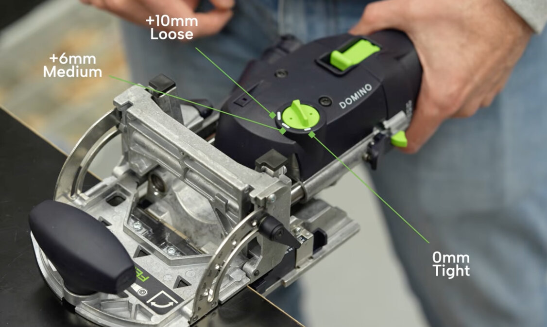
source: Youtube - Makers Manual, Festool Domino DF 500 Every Joint Type in One Video
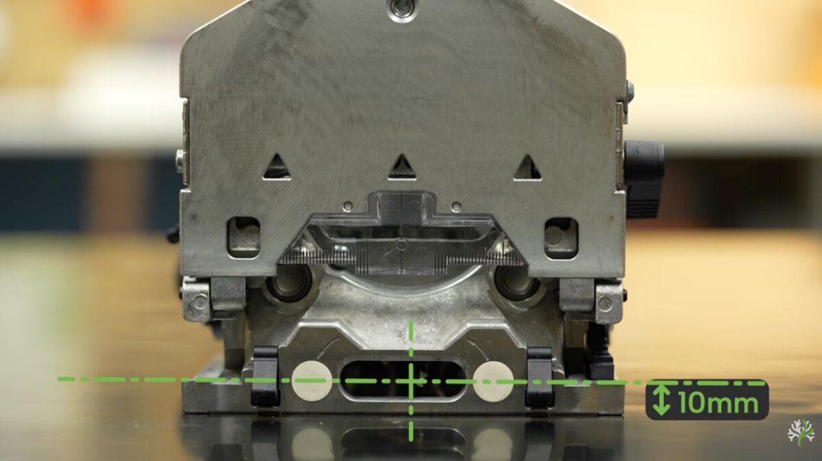
- reference surface to center of the tool is 10 mm
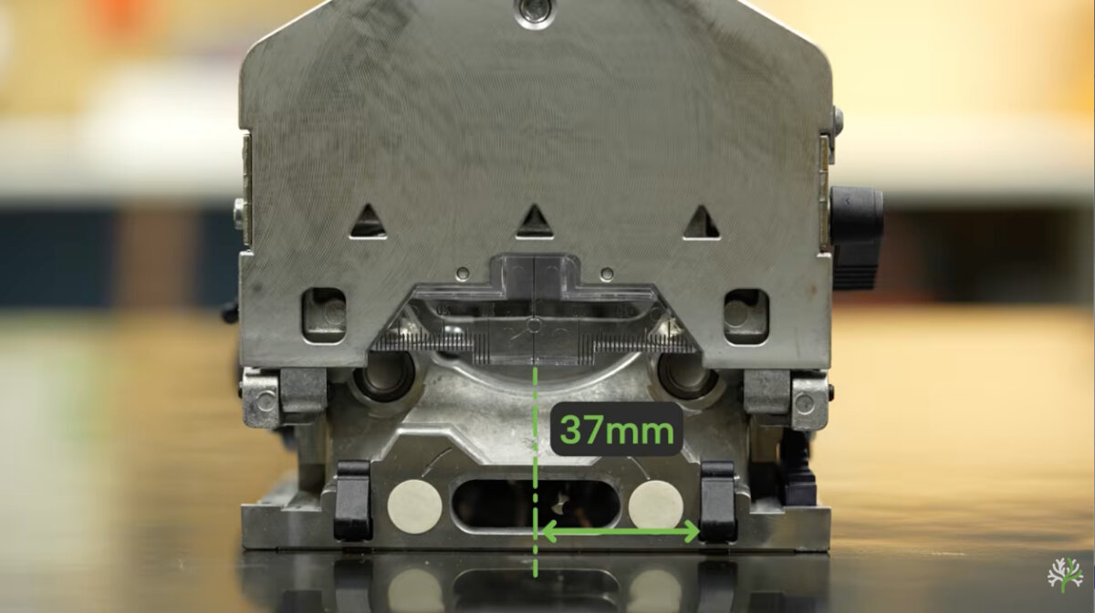
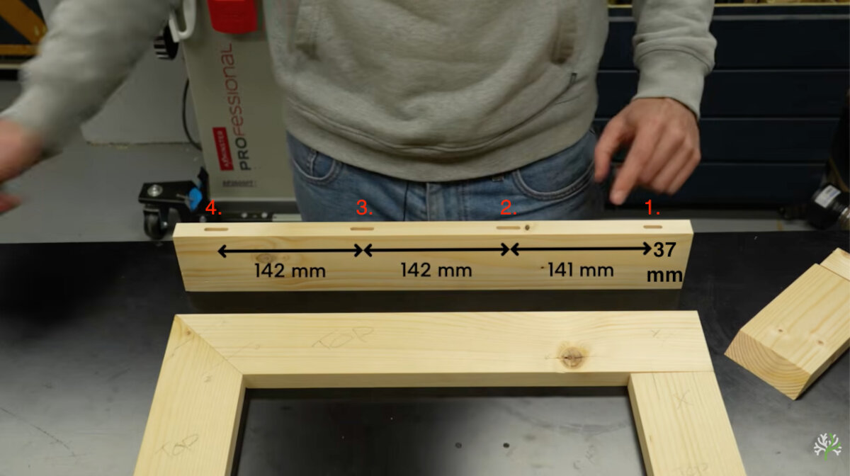
- side stops: distance between edge and center of mortise is 37 mm
- do not overtighten the cutter (mill bit, can be hard to remove)
- plunging into a surface
- vibrations can cause miss alignment
- proper fixture is needed to ensure a secure plunge cut
- tool alignment with the center line
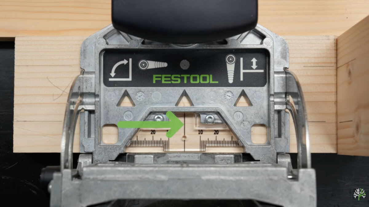
Domino types and sizes
Wooden Dominos (no-removable)
- typical wooden domino sizes (thickness x length)(real length is usually two millimeters shorter to account for the glue)
- 10 x 50 mm
- 8 x 50 mm
- 8 x 40 mm
- 6 x 40 mm
- 5 x 30 mm
- 4 x 20 mm
- select the thickness of the domino
- 1/3 of the material thickness
- for 18 mm plywood -> 6 mm Domino
- use 5x30 Dominos for the 18 mm stock (15 mm mortise depth, no asymmetrical depth needed)
- length selection by
- desired strength
- space constrains
- always reference the top surfaces of your boards! (this avoids problems caused by asymmetry with a 20 mm thickness preset for an 18 mm board)
- when creating a bevel joint, use tight setting for one of the joints and the medium for the others
- multiple dominos for a panel joint
- fist with the stop latches and tight preset
- others with alignment rig and medium preset (avoid over constraining)
- cross stop jig
- references of the edge of the mortise
- tolerances for medium and loose mortise add up
- leave 150 mm to 200 mm between dominos
- mortise 1. is tight, 2. 3. 4. are medium (tolerances add up)
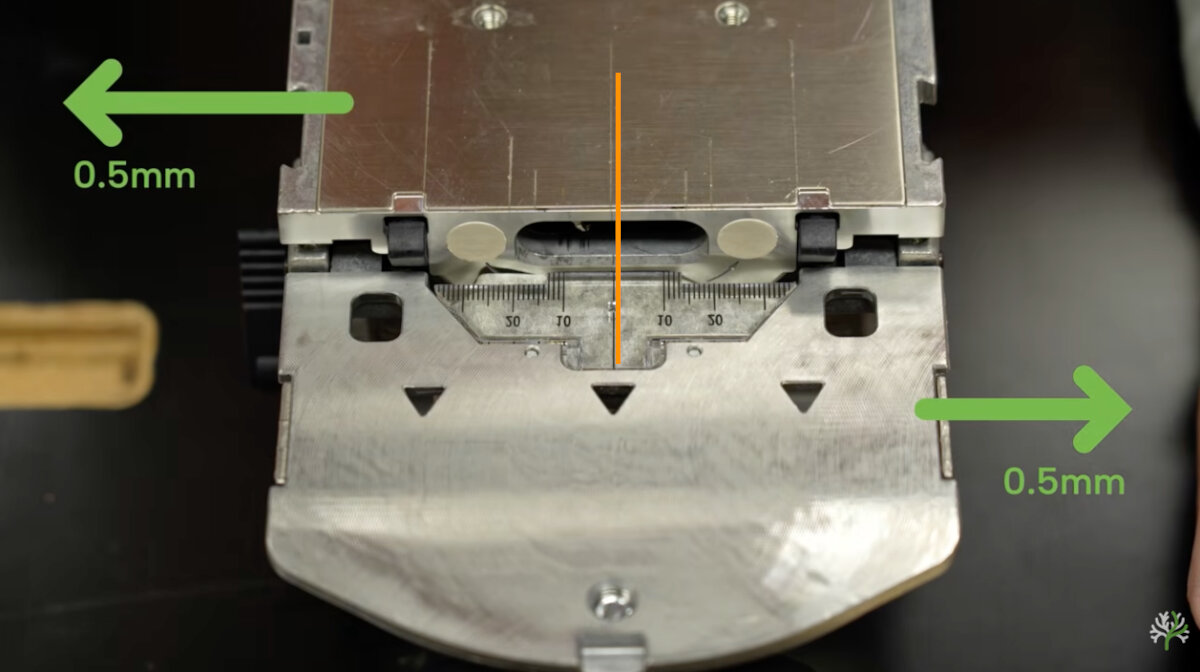
- check if center cutting line and center of the gauge are in line
Metal-Plastic Dominos (removable KV-Sys)
Getting started: Domino DF 500 Connectors - Youtube, Festool USA
How-To: Wiederlösbare DOMINO Verbinder für DF 500 - Düberlfräse 3/3
- removable Domino system is only available in 8 mm and 14 mm
- the KV-System is just a connector, wood dominos should be added to carry the weight
- when inserting the round metal part, first drill to the whole depth
- 8 mm KV-Sys works with 18 mm stock
- 5 mm on each side
- Multiplex plywood is very stiff, 8 mm KV-Sys will be durable
- reddit - Festool Domino choice
- 15 mm side panel (expansion connector)
- 28 mm bottom panel (plastic insert, metal round piece)
- use 'tight' preset for plastic and metal inserts
- use 8 x 36 mm wooden Dominos
- when inserting the split anchor, do not overtighten the screw can shear
- rotate backwards
- for a 600 mm panel width
- use 2 Wooden Dominos for support
- use 2 KV-Sys connectors for
Joint Types
Shelf Joint
Flip the pieces on top of each other and secure them with a clamp to ensure a perfect fit.
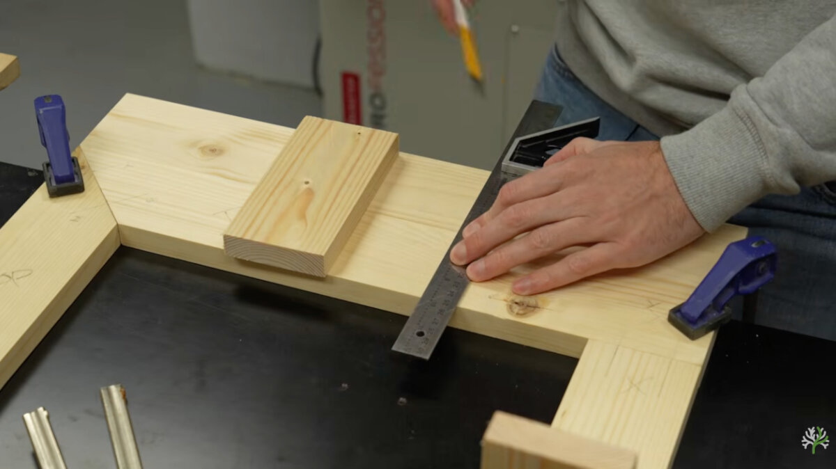
Mark line where shelf edge should be placed.
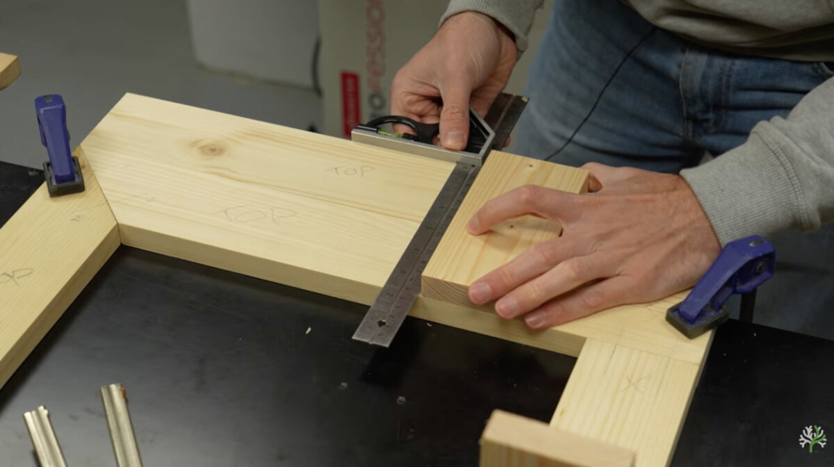
Flip and align the shelf board with the marking line and fix it in place with clamps.
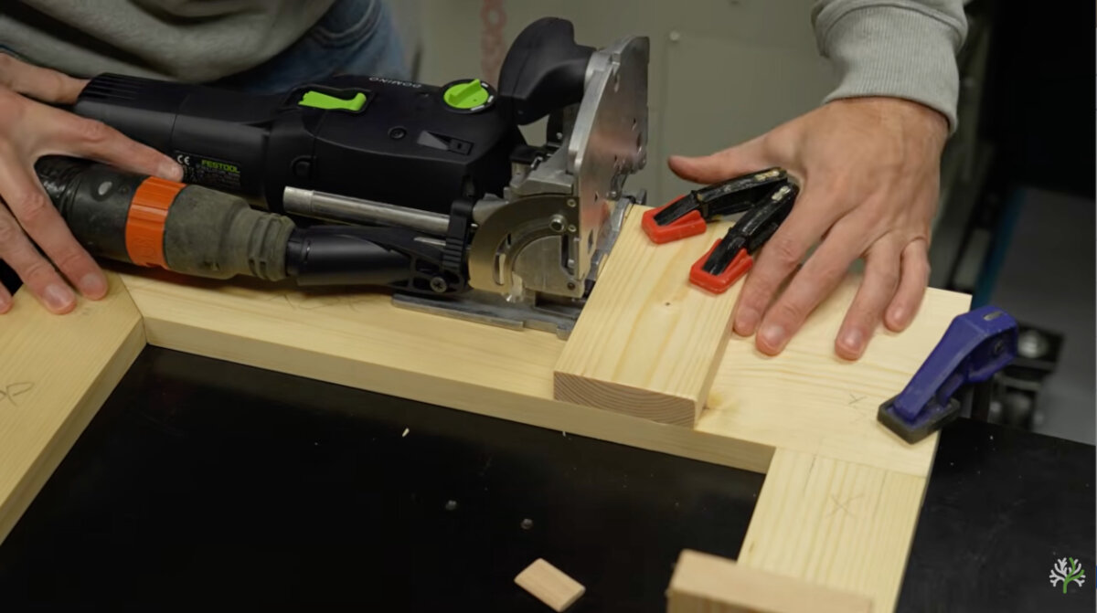
Cut horizontal mortise.
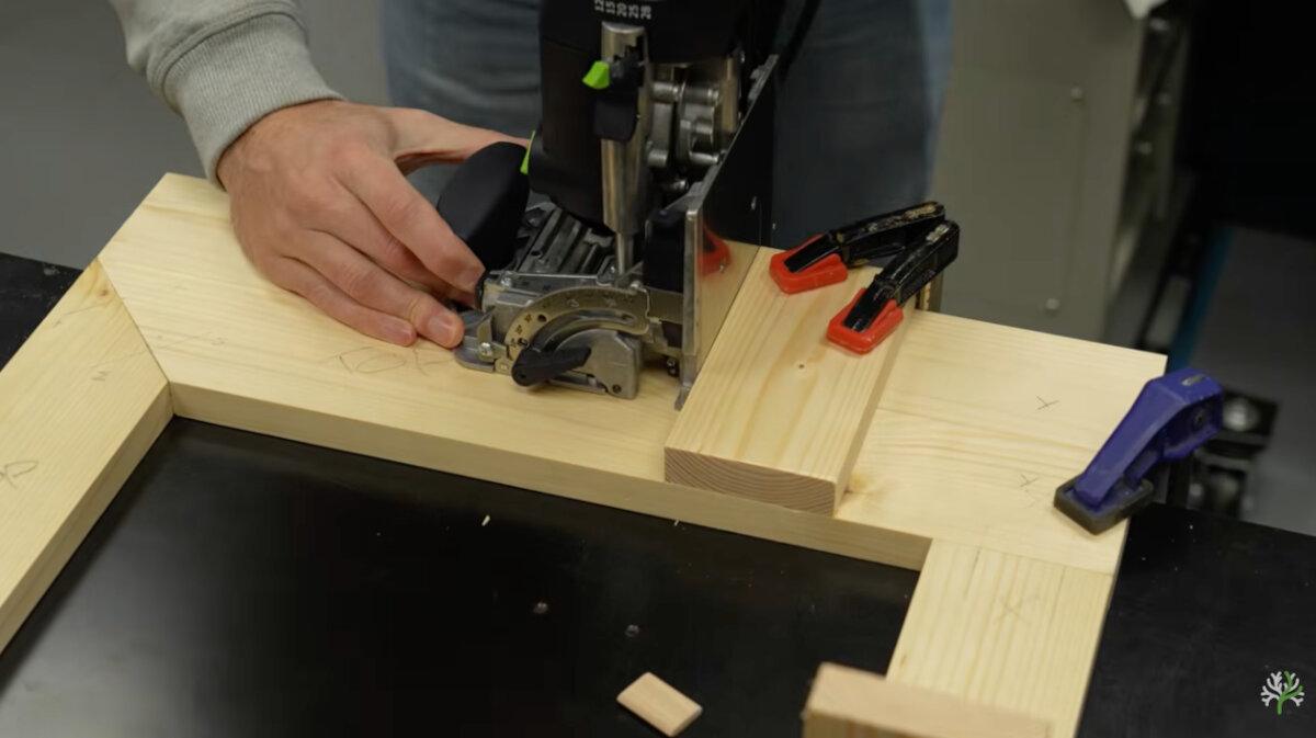
Plunge the vertical mortise.
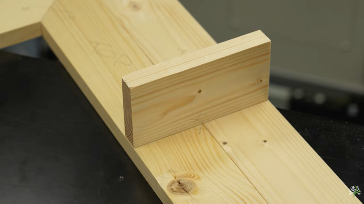
Final shelf joint.
Edge Butt Joint
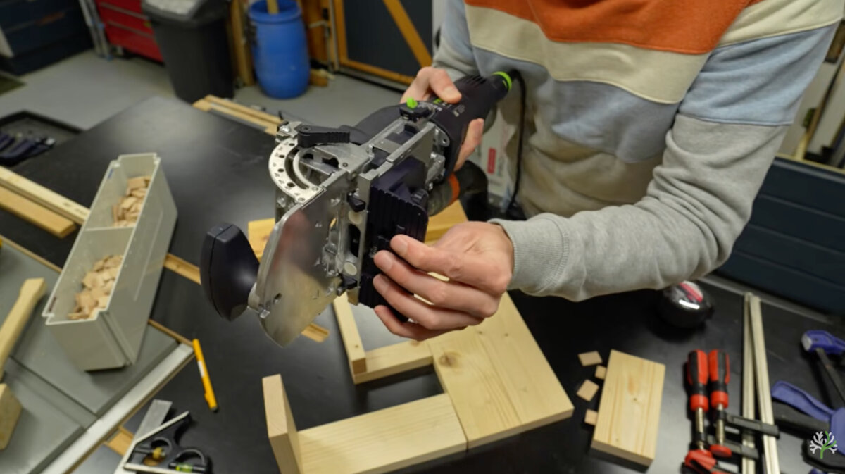
Add the additional support bracket
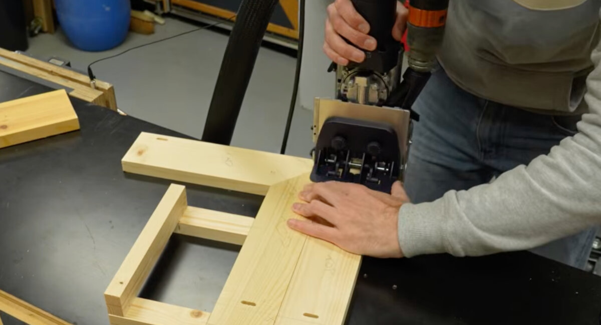
Plunge form both sides.
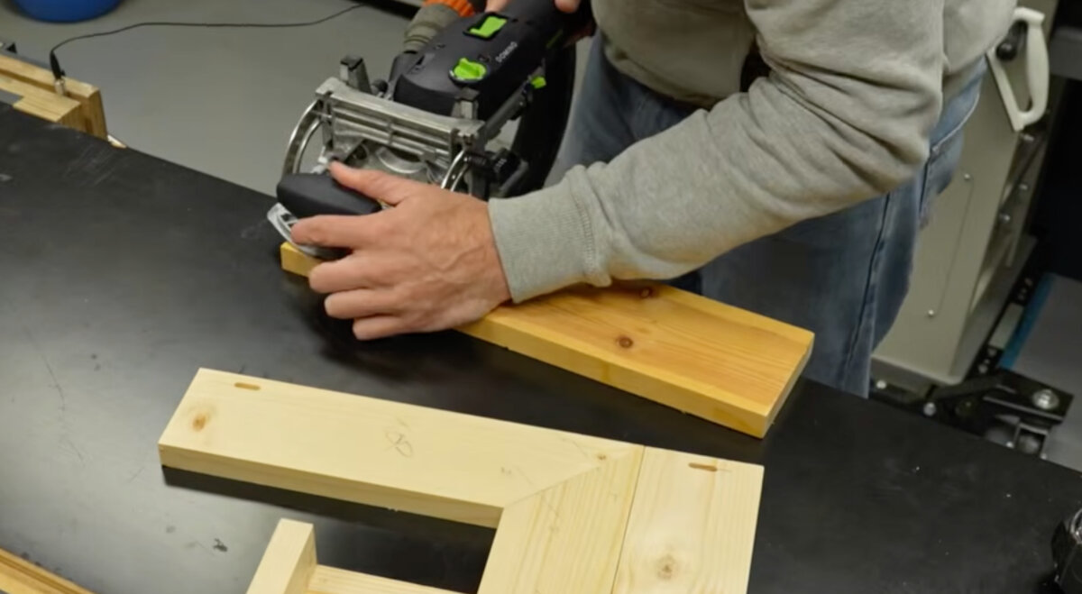
Add mortises to both sides of the vertical board.
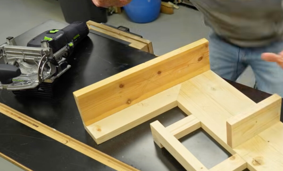
Assemble the both boards.
Since the furniture should be disassemblable, the removable KV-Sys D8 series will be used in conjunction with wooden dominos. I watched this video, that shows the application of a mixed joint type.
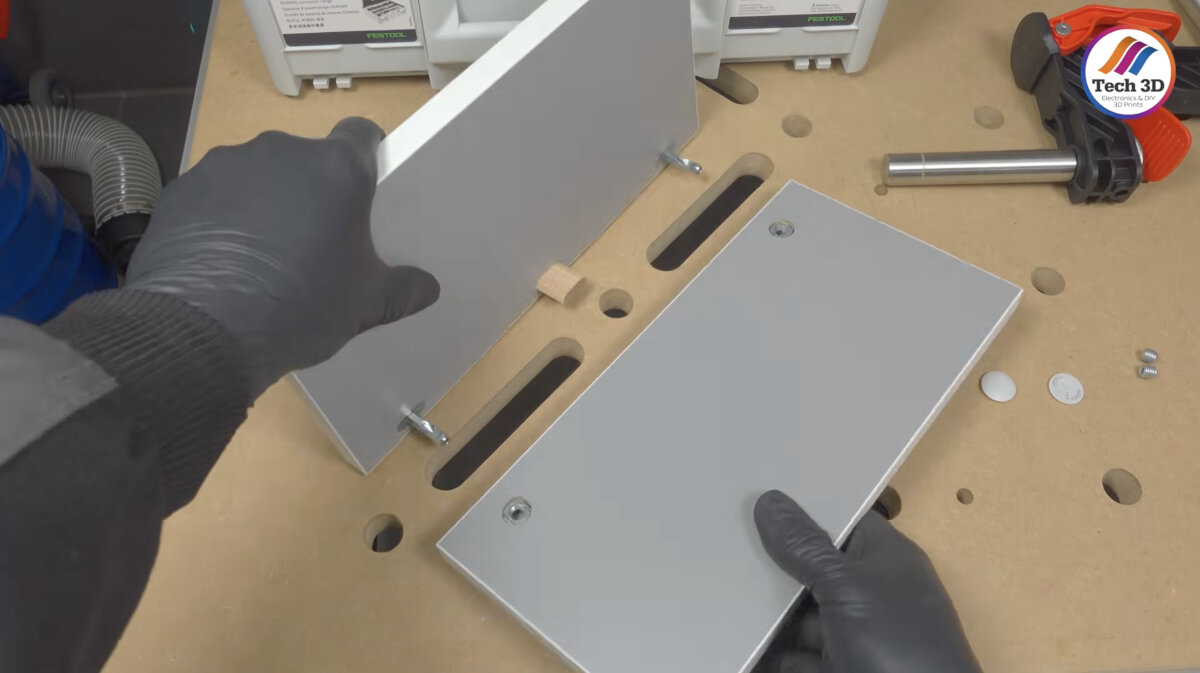
Mixed Edge Butt Joint with removable connectors.
- select tight mortis on one side of the connection and medium/loose on the other side for easy disassembly
Selecting the right fastener
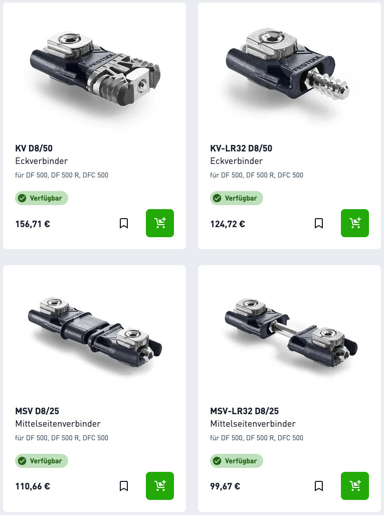
- KV D8/50 for edge connection with higher loads
- KV-LR32 D8/50 for mounting shelf boards
Designing the Printer Cabinet
Ergonomic Design
I took all the important measurements from Benedik's printer shelf and started form scratch. For a better ergonomic design I did some research on human centric design. The most important takeaway was that a cutout is needed for the knees and the feet to avoid interference while working.
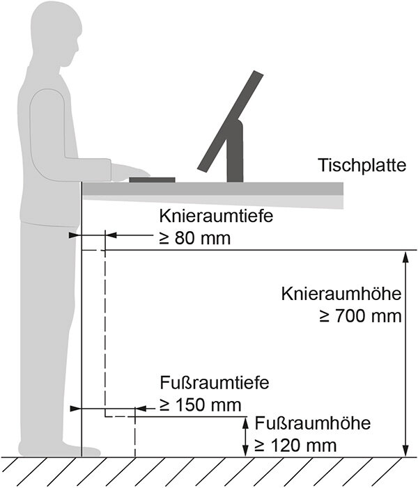
source: BGN Branchenwissen - 6. Gestalltungsanforderungen, German
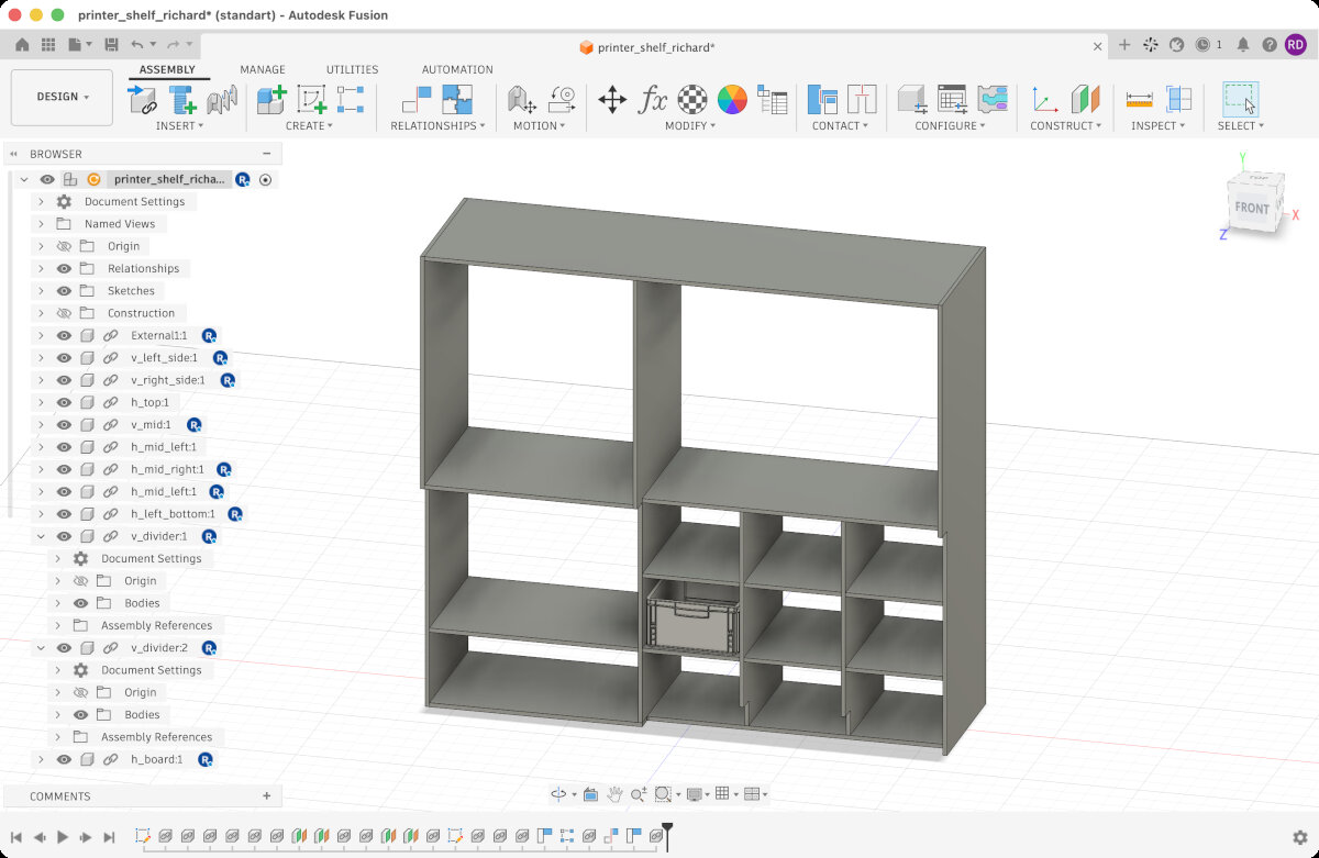
For better ergonomics a cutout around the feet is added. It is visible in the lower left corner of the shelf.
To allow for different configurations after assembly the height of the small boards can be changed with shelf board pins.
To keep the design flexible, I added parameters for the back panel and the back panel slot. With these parameters set the back panel position and thickness can be changed dynamic if changes are needed. The implementation of variables across files in fusion is not very intuitive. I watched this video to link parameters between files.
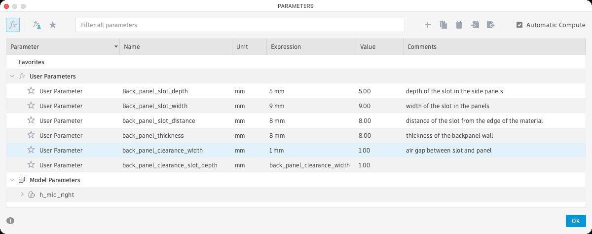
Parameters for the back panel and slot.
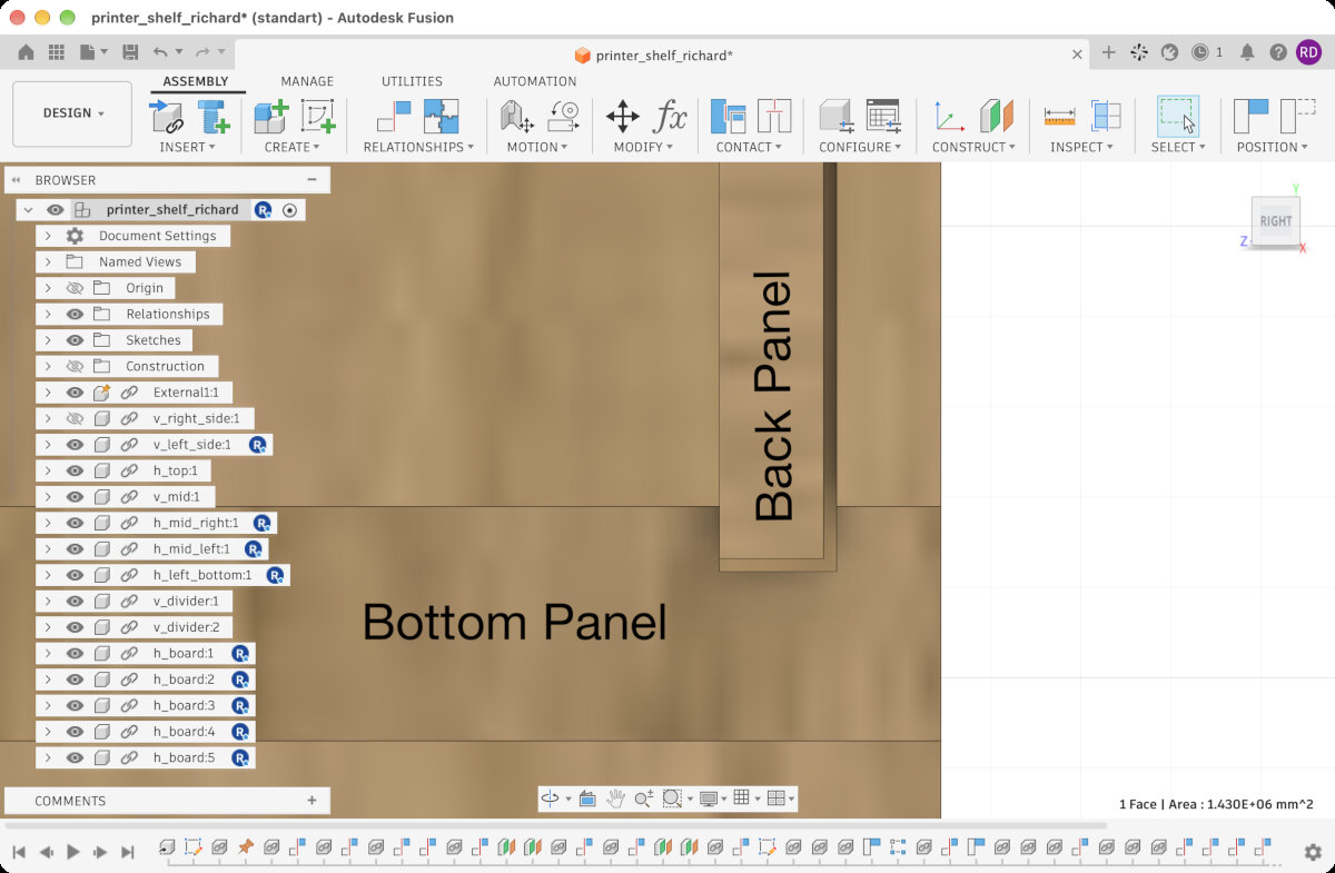
The air gap between back panel and bottom panel is parametric across files.
Door Mechanism
The door mechanism is a crucial decision for the design of the resin printing work area. In professional chemical laboratories fume hoods (Wikipedia) are used to remove toxic process gases. In the best case scenario a transparent door could be lowered vertically. The remaining slot allows the machine operator to reach with their arms into the working area and look through the window above.
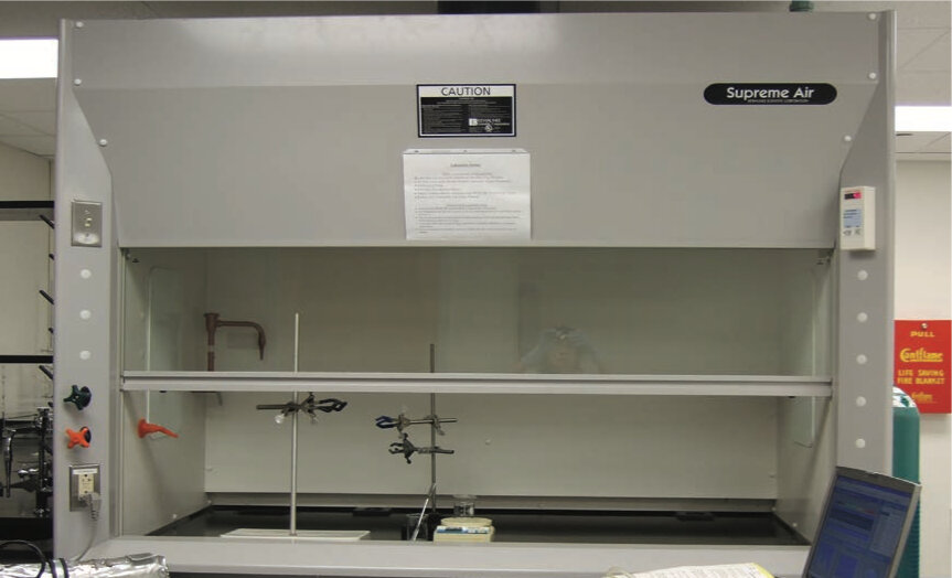
Ideal design for a working environment that emits volatile organic compounds. The vertical door allows to be lowered for optimal airflow into the exhaust.
source: fume hood - Wikimedia

The furniture fittings for vertical door systems are not trivial since they need to deal with counterweights and fallback mechanisms. A couple of relevant fittings for vertical doors are listed below.
The issues with these systems is, that they are not easy to implement. Additionally, they require extensive vertical space to allow for opening the door fully. In comparison to sliding door fittings that slide sideways they are double or for times the price. For these reasons the vertical door design got canceled in favor for a sideways sliding door system. To still limit the airflow a transparent removable acrylic sheet will be implemented in the top half of the printer cabinet.
After longer considerations with Benedikt, we decided on building a sliding door that is made out of a single panel that slides over the FDM printing area. The window in the sliding door is made of orange PMMA Acrylic that blocks the UV light form entering the working area. The glass is split into three different sheets since the acrylic already existed in our lab from a previous project. The seems between the PMMA sheets could be covered/reinforced with H-profiles for 4 mm sheets.
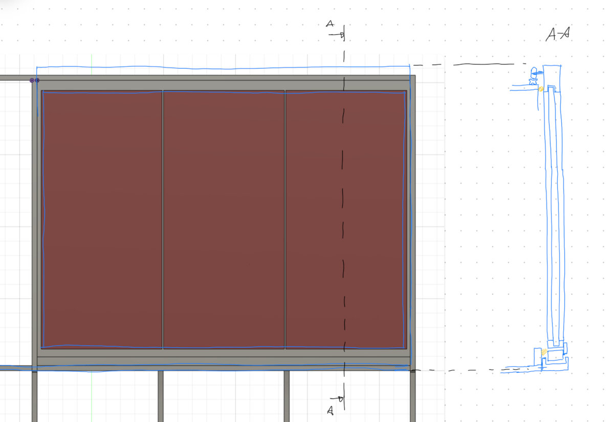
First draft for the sliding door.
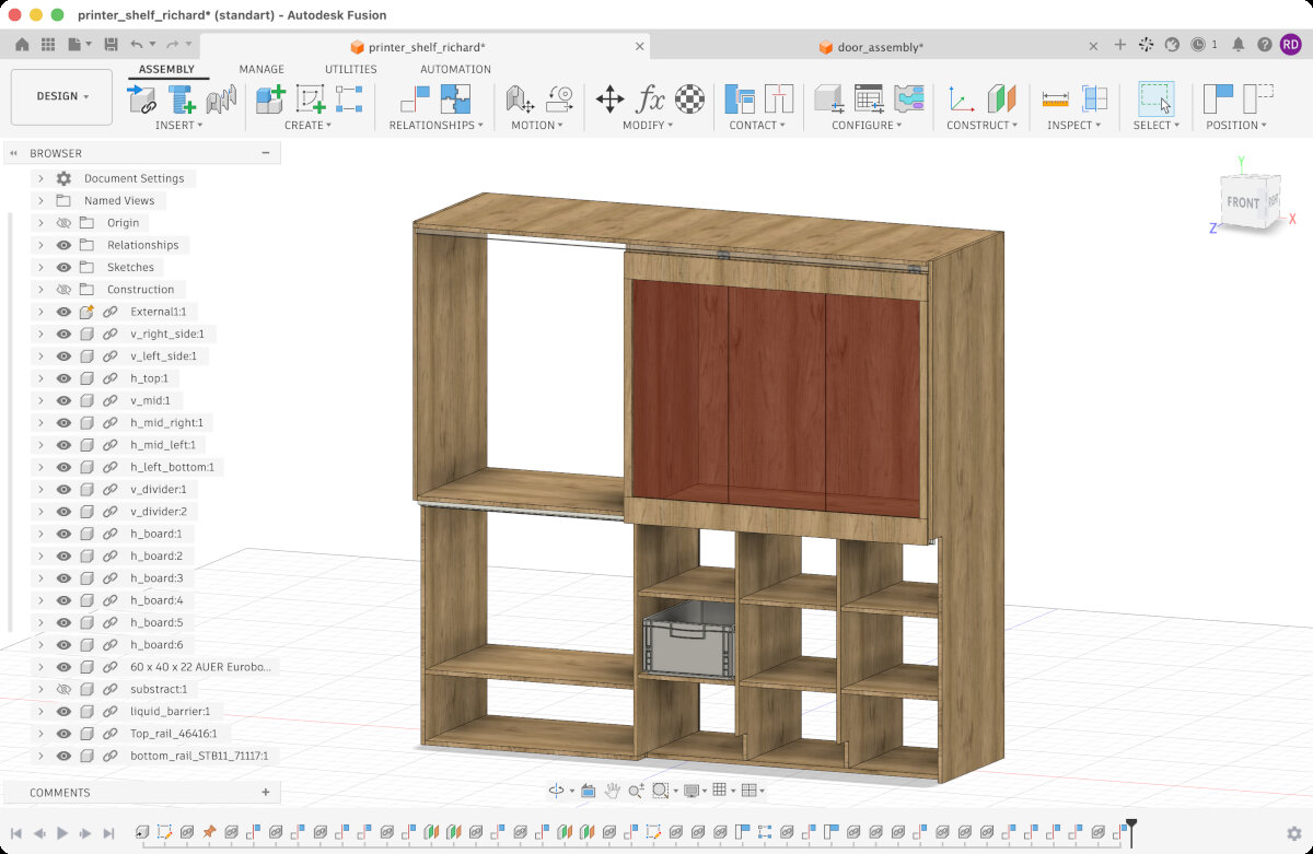
Overview of the 3D priter shelf. On the left will be the compartment for FMD printers, on the right the resin printer will be operated.
After extensive research on furniture fittings I choose the Hettich TopSilde 25 line for the door system. The following products will be used.
- Top Wheels - Hettich TopLine 25 Set
- Top Profile - Hettich TopLine 25 Profile
- Lower Guide - Hettich STB 11 Set
- Lower Profile - Hettich STP 11 Profile
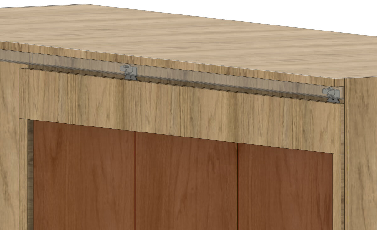
Profile on the top for the hanging door. The profile is rendered transparent to visualize the top wheels.
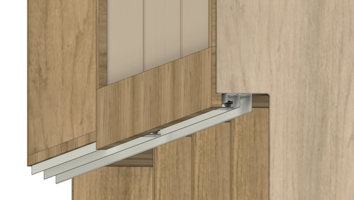
Profile on the bottom for guiding the door. The metal extrusion would allow for a dual door system which will be unused in this case.
Additional the door needs to be sealed. For sealing a sliding door a rubber seal could cause too much friction, why I choose this brushed door seal. I assumed the seal can be compressed form 6 mm to 4 mm in thickness for sealing properly.
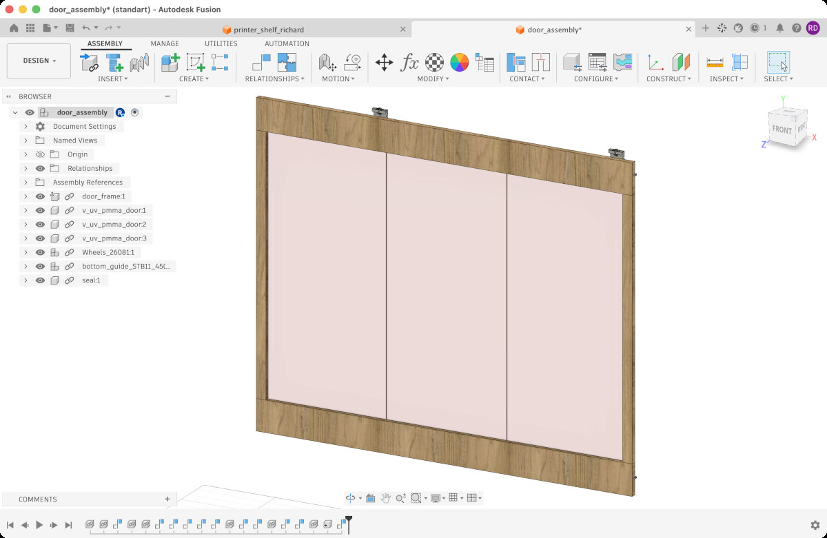
The door frame is made of four pieces that will be assembled after manufacturing with wooden Dominos and glue. The tree acrylic panels are mounted into the frame with silicone to create a proper seal.
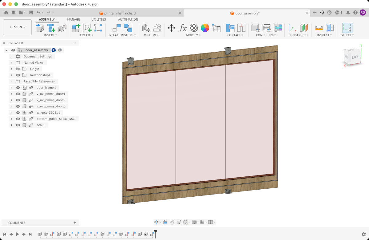
Rear of the door with grey door seal.
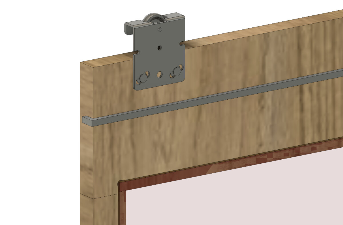
Rear of the door. The seal wraps around one side to ensure a sealed side of the door.
To Dos:
- [] add cutout to the baseboard
- [] add foot cutout at the FDM area
- [] add wall mounting points
Filtration system
Work in Progress
This section is not yet filished since the ventilation and filtration system will be built after this assignment.
VOCs - Voliaile Organic Compounds are smaller than normal dust particles, thats why normal HEPA filters are not effective for filtering the VOCs out. Activated Carbon needs to be used to filter out the compounds.
- in-printer carbon filters are usually exposed to such high concentration of VOCs that they get saturated very quickly. They need frequent replacements
- ventilating the printers directly is helpful
- metal fan housing and metal fan ducts
- no static sparks
- ground all the metal components
General Information on Milling
Introduction to Milling
- create tabs to prevent part movement in the last milling section
- wood/soft materials
- single flute end mill
- two flute end mill
- metal/hard materials
- multi flute bits
- do not expect your stock to be flat
- plywood has internal tensions, can bend warp parts are cutout
Security Introduction
Ferdi our instructor gave us a security and technical introduction to CNC mills. Below are the main takeaways listed.
- mill bit should be as short as possible, as long as necessary
- example: 8 mm sheet, 10 mm mill
- the saw/mill dust can explode or catch on fire by friction
- choose the right spindle speed, feed and step-over
- use sharp tools
- vacuum perpetuates the fire
- check fire extinguisher location before milling
- wear impact tested security glasses, keep them clean
- tighten long hair
- do not wear gloves
- kickback happens on CNC mills as well
- moving axis can cause pinching injuries or cut fingers
- hardened mill bits can shatter into pieces
- stock mounting
- vacuum beds
- check for air leaks
- check if vacuum can hold enough pressure when parts are cutout
- clamps
- model them into your cad design
- check for interference with the tool head
- check if sheets are moving before milling
- vacuum beds
Generating the CAM File - Fusion 360 CAM
Only the door will be manufactured
For this assignment only the door of the printer cabinet will be manufactured since manufacturing the whole cabinet and assembling everything is too much work for a single week.
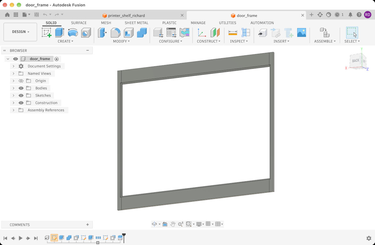
Wooden parts of the door assembly.
The design file of the door frame can be downloaded here:
door_frame.step
To generate the gcode I decided to use Fusion360's built in CAM environment. I used Niclas' documentation to create the milling setup in fusion.
Nesting
Nesting is a process of maximizing the parts per stock sheet. The goal of the nesting process is to reduce the material waste and use the stock as efficient as possible. Nesting can be done manually by aligning the contours by hand or automatically with any of these tools below.
- Deepnest (Open source)
- altair Hyperwoks/Inspire
- Fusion 360 license
- 3D expert
- Ansis discovery
- Creo pro e
- simens Nx
- solid edge
Stock Setup and Work Coordinate System
After I finished the design of the printer cabinet, I downloaded the for bodies of the door frame as .step files and uploaded them again to a new assembly file. After reading Benedikt's, Niclas' and Jakob's documentation, I designed my stock piece at 2400 mm x 1250 mm to fit the machine bed. For the layout I nested the four parts by hand without any nesting software.
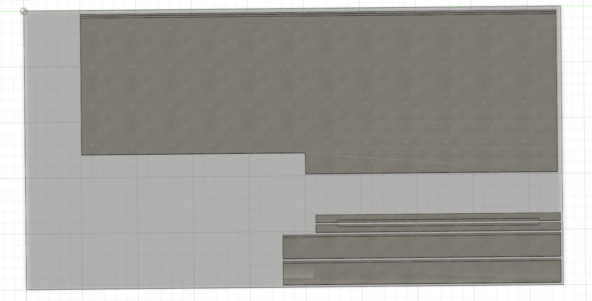
Manual nesting of the parts. The largest piece will not be manufactured, it is just there to ensure the remaining stock can be used later for one of the sidewalls.
The additional side panel can be downloaded here:
The Work Coordinate System (WCS) needs to be placed at:
- X along the long side of the stock
- Y along the short side of the stock
- Z = 0 at the bottom of the workpiece
These are the settings for my milling setup in Fusion
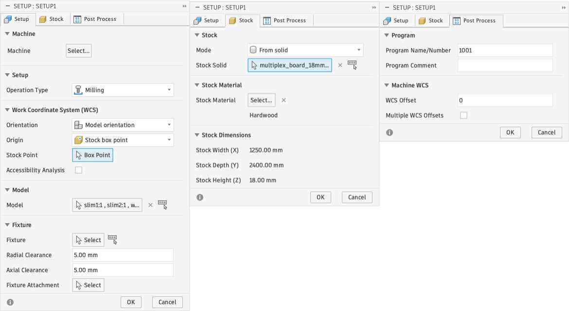
Fusion360 CAM settings for the stock setup.
Pockets
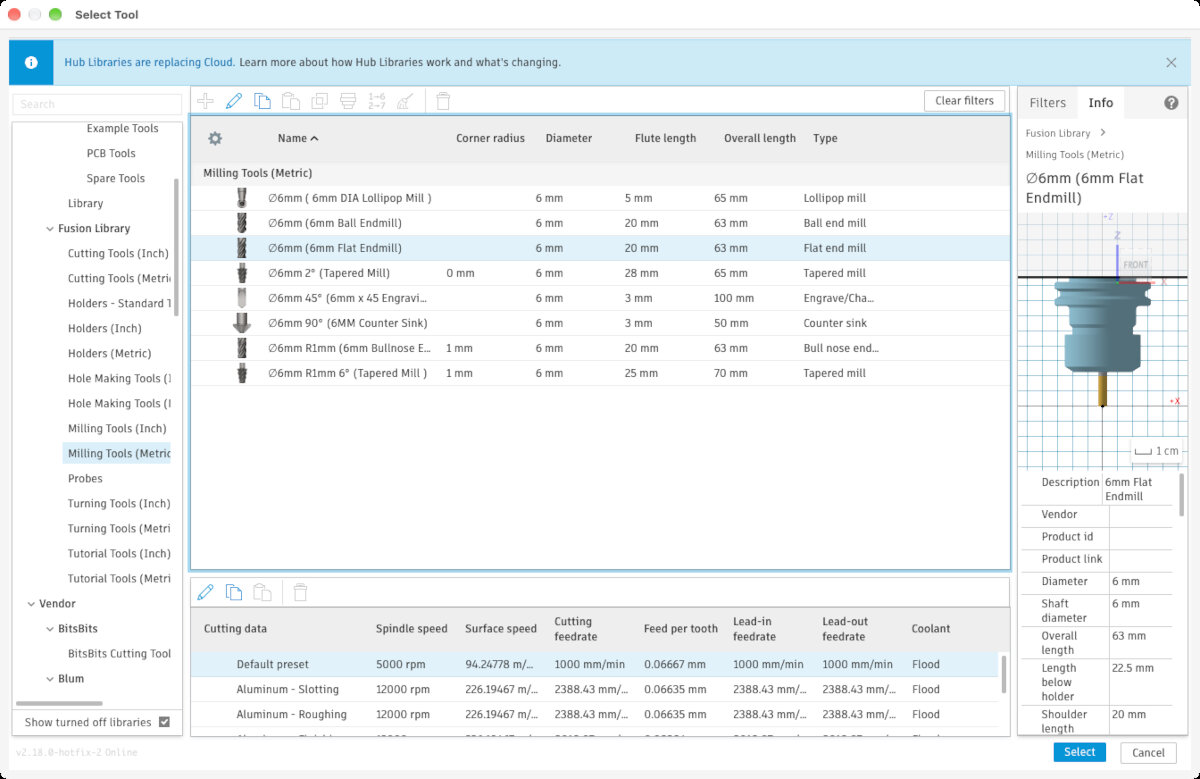
A 6 mm standard end mill will be used to mill out the parts form the 18 mm plywood board.
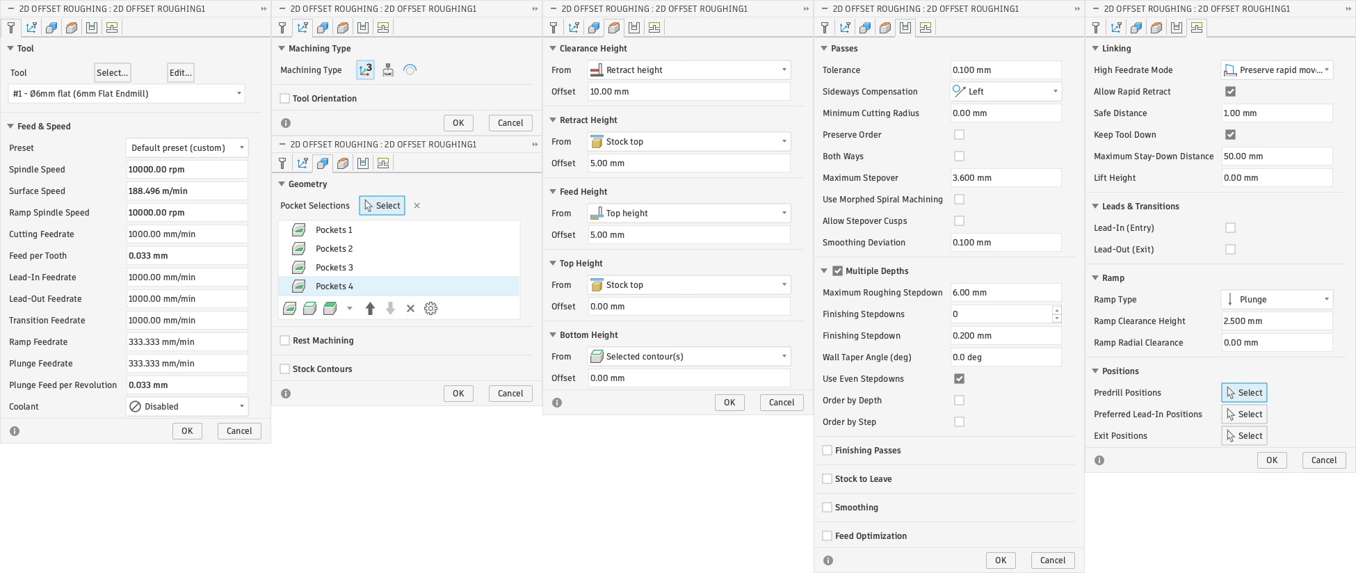
Fusion360 CAM setting for the 2D pocket.
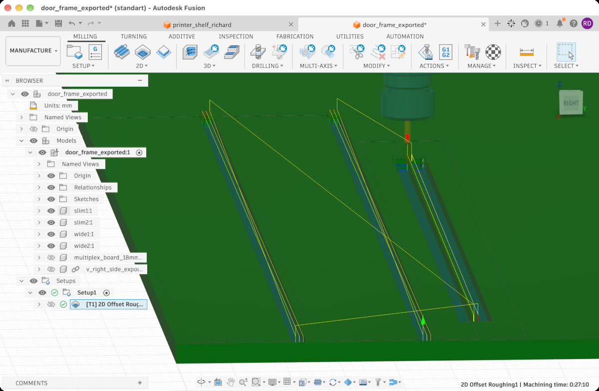
Visualization of the pocket operation.
Contours
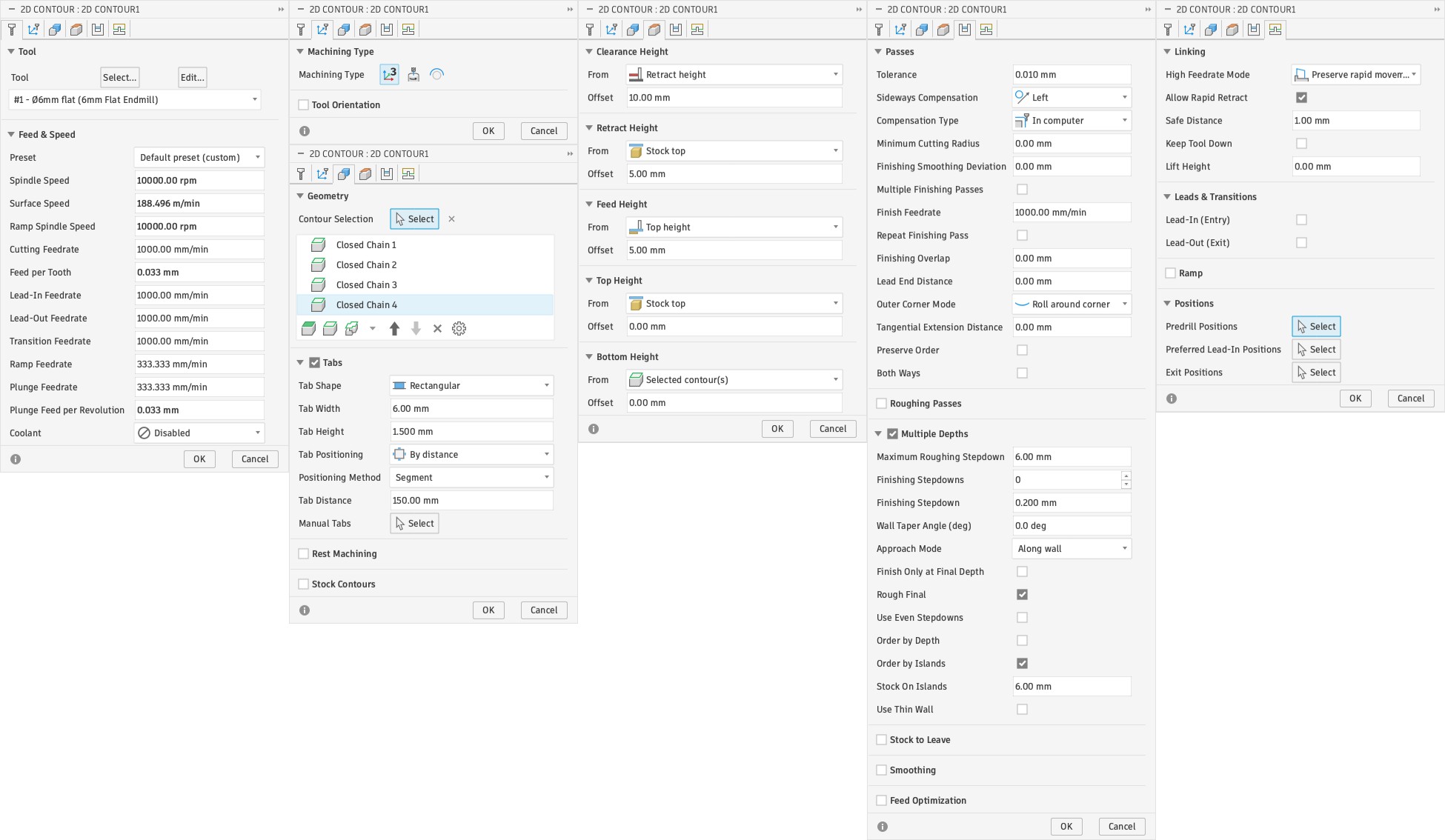
Fusion360 CAM setting for the 2D contour.
I enabled tabs every 150 mm along the straight edges of the piece. The tabs are 6 mm wide and 1.5 mm high This keeps the parts in place even after milling.
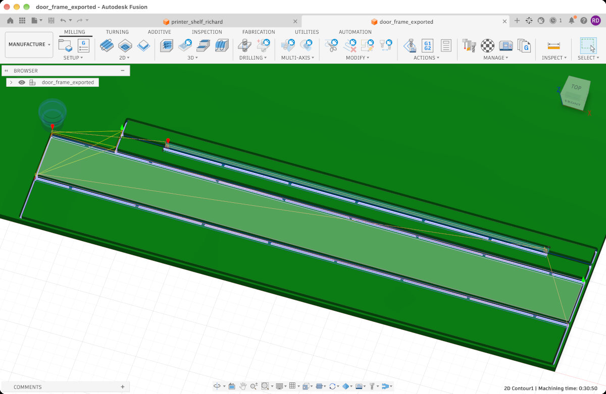
Visualization of the contour operation
The distance between two parts should be 10 mm for a 6 mm tool since the remaining material will not be enough to connect the parts. Reducing the distance between parts to 7 mm can help. Or place the tabs manually.
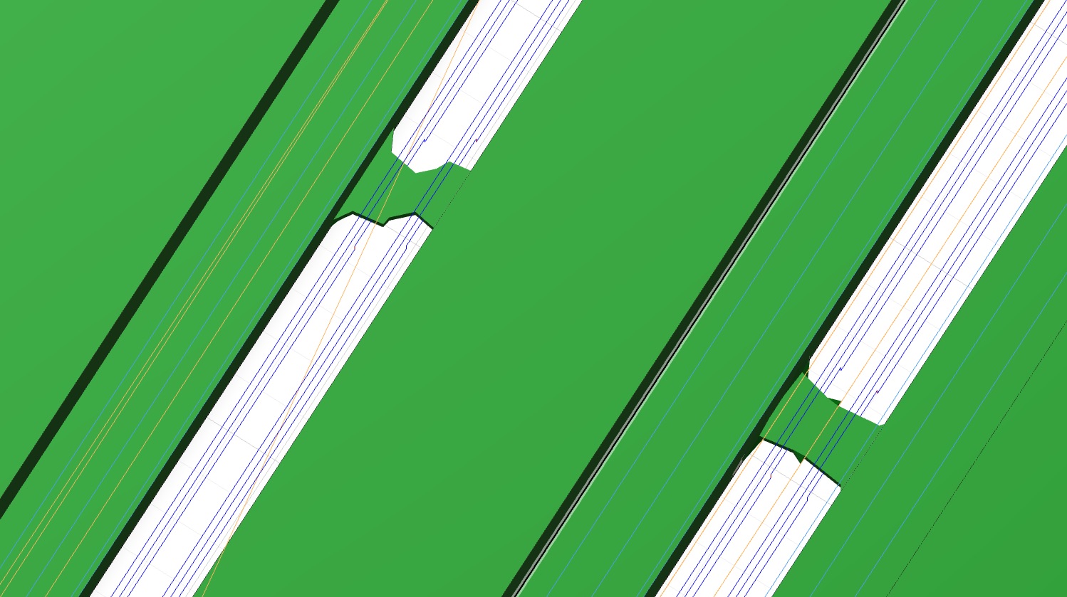
Misaligned automatic tabs. The tabs that I generated automatically with a distance of 10 mm between parts can cause issues.
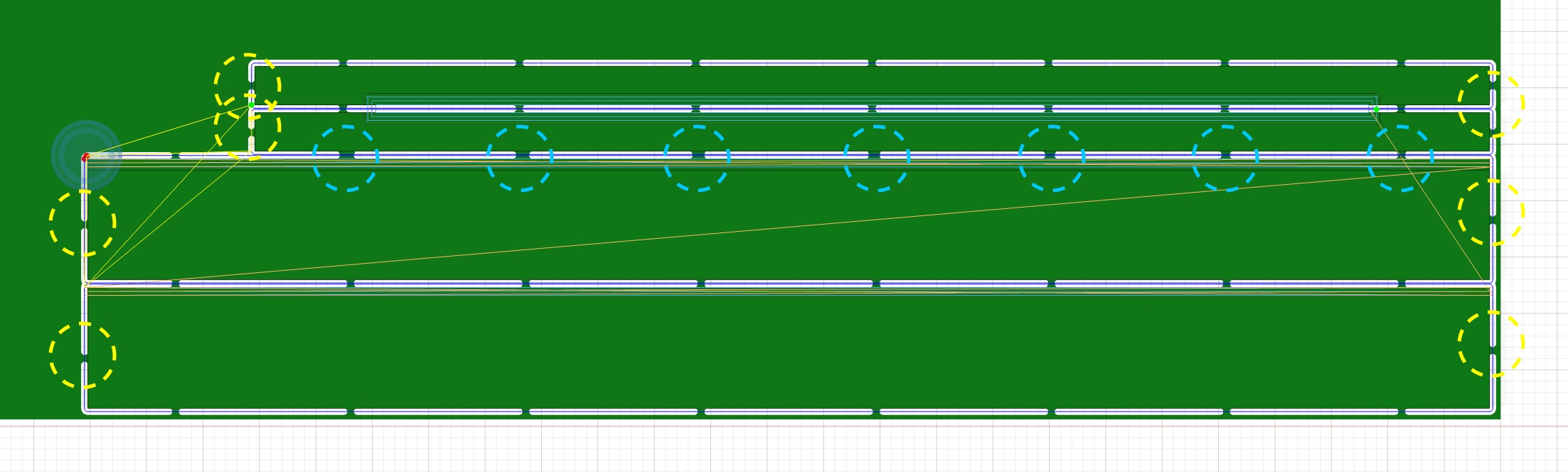
Final tab setup. Turquoise: reduced gap between parts to 7 mm, full overlap between tabs; Yellow: manually placed tabs.
Post Processor
The last step is to post process the CAM file and create the machine specific gcode. The post processor is a piece of software which is usually fully custom or customized for a specific machine. It should make sure a command is executed as planed by the user. Different CNC controller boards can interpret the same gcode commands and execute different actions.
In our example the WK2516F from CNC-Multitool needed the specific post processor. It will not be uploaded here since the original post processor is not my own work. The original post processor without modifications can be found here.
The custom post processor can be added to Fusion in the post processor section. Add and select the .cps file before post-processing.
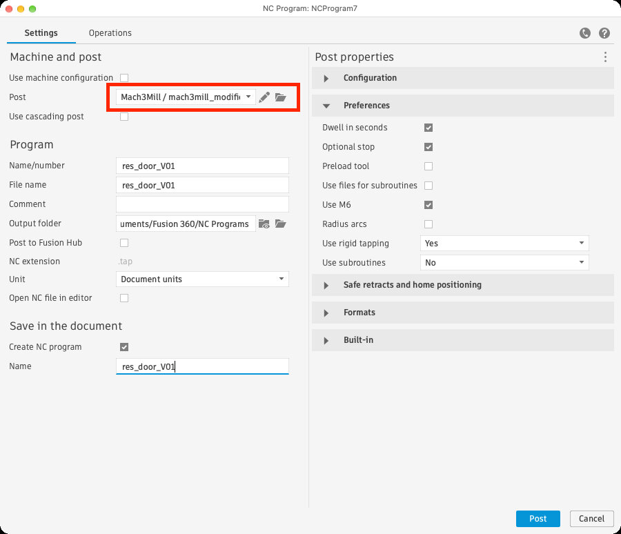
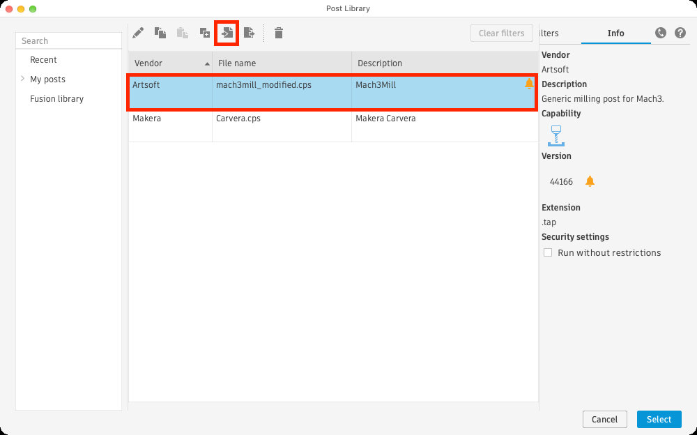
Fusion can handle multiple post processor for different machines. Add and select the machine specific post processor.
Updated Nesting
After checking our material storage I found the left over stock form Jakob's CNC Assignment and decided to use it. Efficient manual nesting can already be seen in my Computer-Controlled Cutting Assignment, but this time I used an screenshot form Jakobs nesting insed of a possibly distorted camera image.
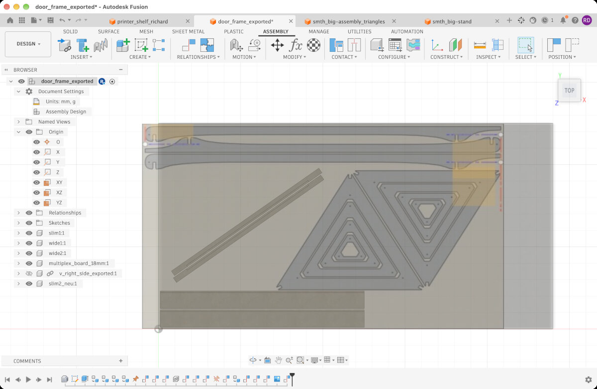
Jakob's nest overlayed onto my parts.
I repeated the gcode generation process again as described above.
After processing the file, the gcode will be generated and saved locally to the computer. My gcode was generated for a 6 mm flat end mill. In this case the gcode has the .tap format.
As documented in Benedikt's - CNC Assignment the G28 command needs to be removed to avoid issues with the dust shoe.
"G28 (home) commands were removed to prevent the dust shoe from crashing into the toolholder, since it does not automatically retract when homing."
Here is the final gcode, that was used for milling.
Manufacturing the Door Frame
Setting up the Machine
The operation and setup of the machine was described already very well in Benedikt's CNC Assignment
Stock Alignment and Fixturing
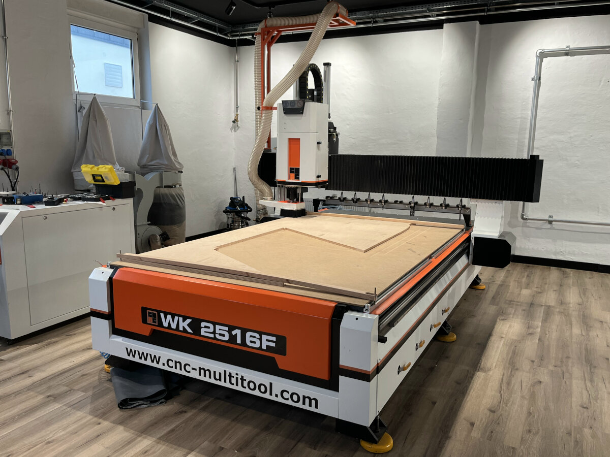
The W2516F CNC from CNC-Multitool has a vacuum bed with an MDF waste board on top. The MDF is porous enough to pull air through the board. To increase the airflow through the board it is recommended to remove the top layer of the waste board. Since my stock is a leftover piece from Jakobs milling project only a fraction of the vacuum bed is covered with stock material. The large gaps in the stock allow for too much airflow and therefor to little adhesion to the bed. To avoid movement of the stock we added additional clamps on the sides.
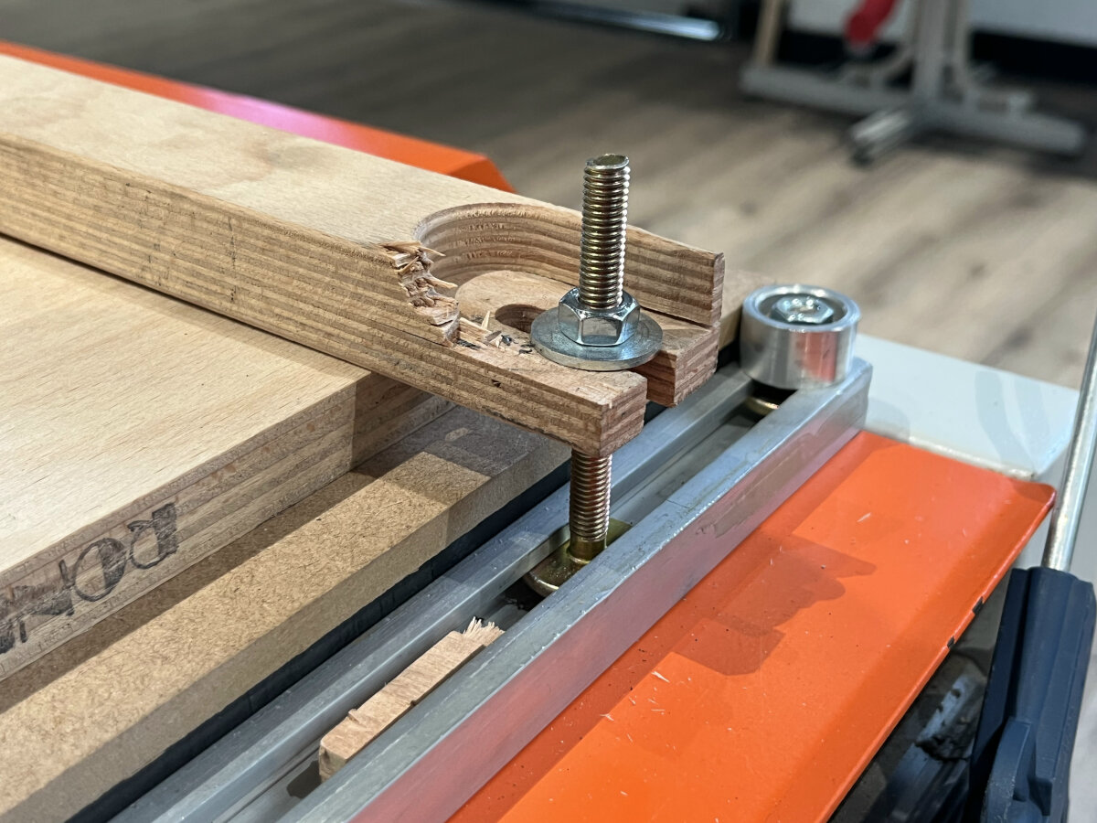
Clamp bars mounted onto the side rails of the CNC. These clamps are made of wood and will most likely not damage the tool when a crash occurs.
Set the WCS
The Work Coordinate System needs to be set in exactly the same place as in the CAM design.
Lowering the mill to the bed until the piece of paper can not be moved anymore. Set Z = 0.
Milling the Pieces
Tool length can cause crashes
The standard tool length set in the Fusio360 library does not match the tool length of the tool used in real life. The real tool is longer and will collide with the surface if the Z = 0 is not set properly.
To double-check the gcode before milling, set the Z height to 100 mm above the stock to do a dry run. This helps to estimate where the cuts will be made and if a collision with clamps is likely.
Milling the board.
The current position of the tool head and mill can be supervised in the UCCNC control software.
Time laps of the contour milling process.
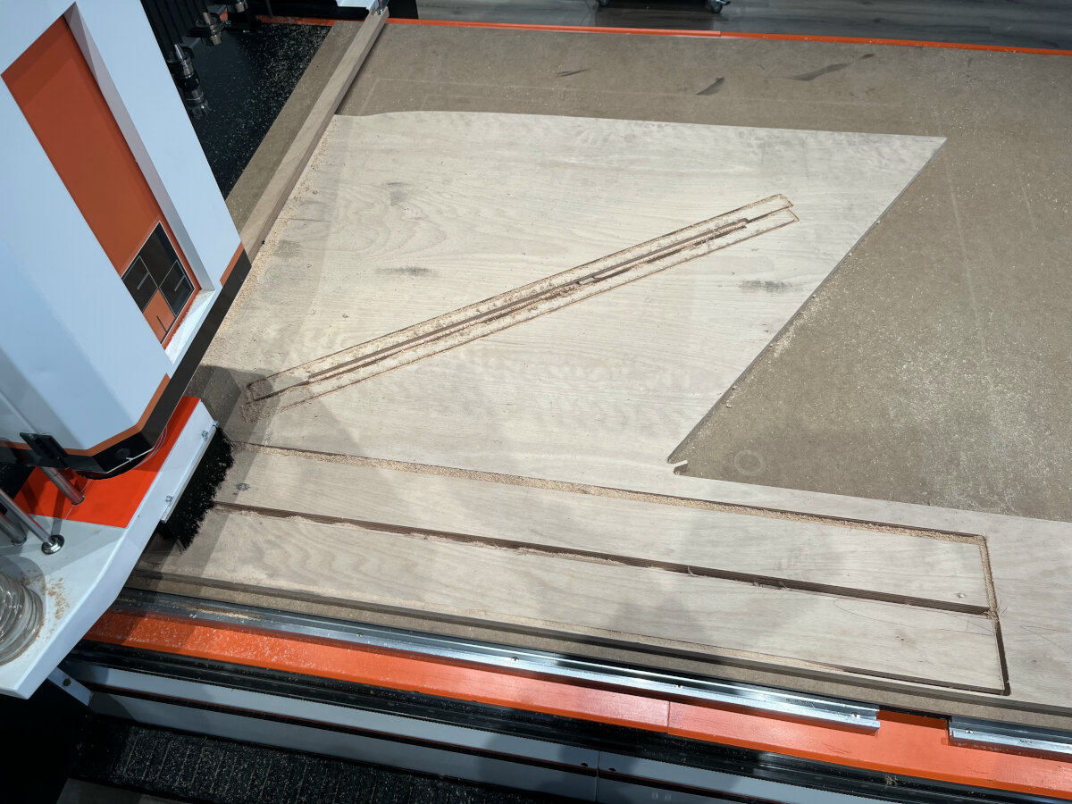
Result after the milling the boards.
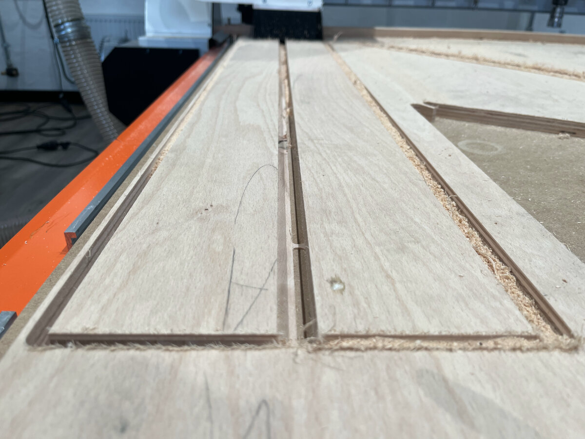
The edges which are parallel to the grain of the top layer result in nearly perfect edges without clean-up.

Milling in a 45° angle to grain of the top layer causes a large amount of chips to form.
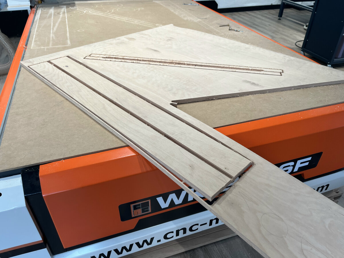
The Z-height was perfect, since the boards could be removed easily without deep groves in the waste board. The size and amount of tabs was perfect (6 x 1.5 mm per tab, 200 mm spacing).
Post Processing
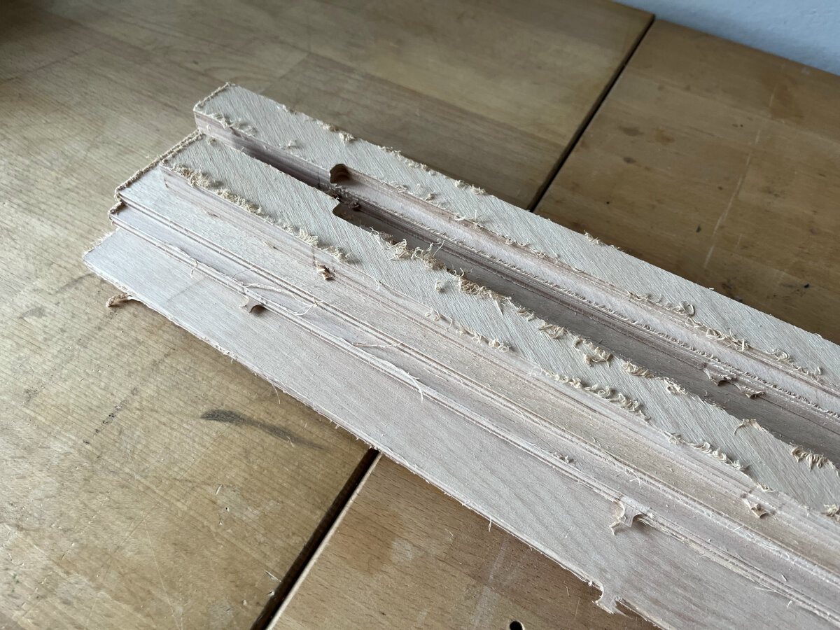
Parts before finishing.
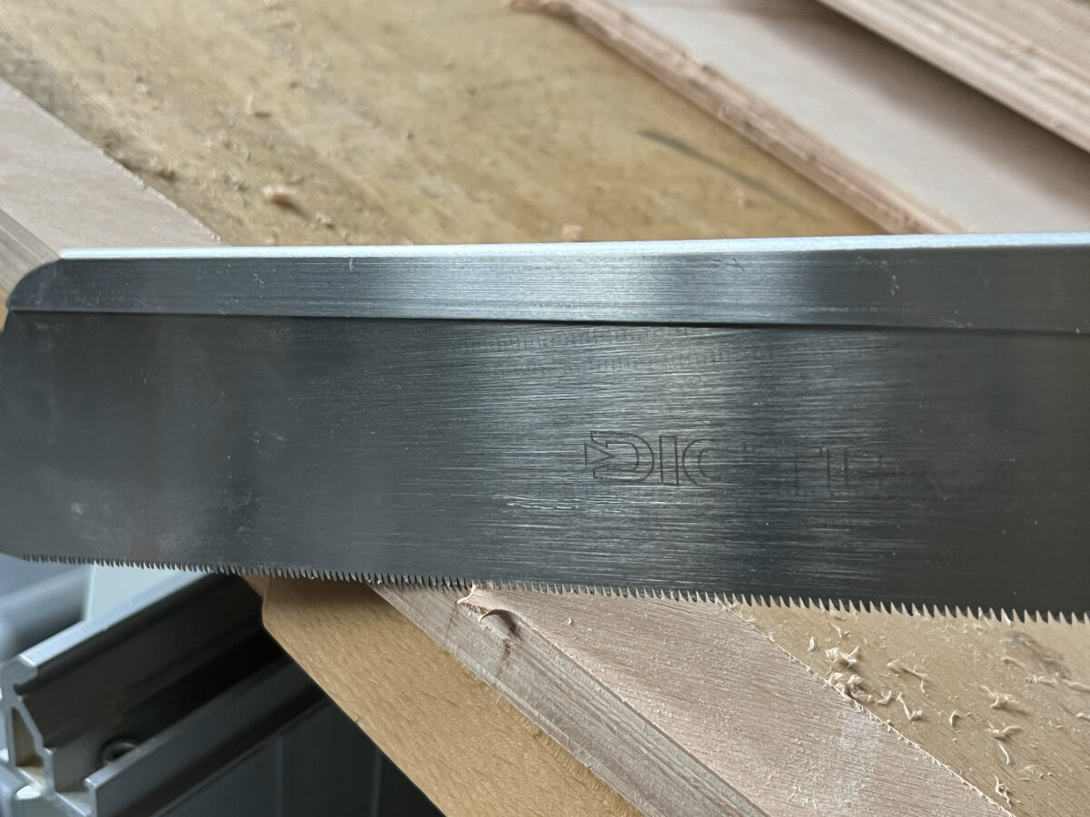
Removing the tabs with a Japanese saw.
Since the whole frame of the door is relatively fragile and thin I opted for the 6 mm Domino type. The Multiplex sheets are 18 mm and I choose the 20 mm thickness preset, which results in a slightly off center mortise which should be no problem. All the slots that I milled were manufactured with the tight setting and 20 mm depth.
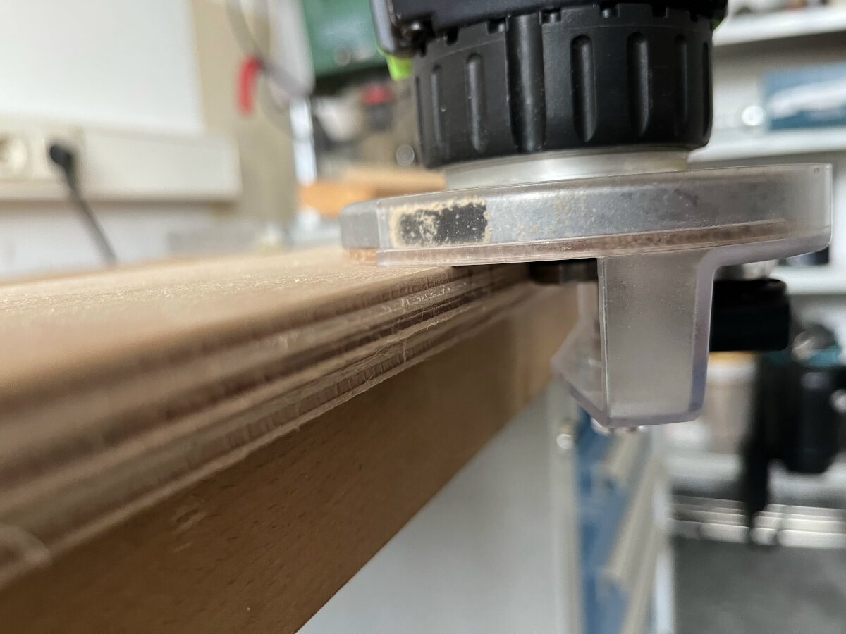
Finishing the edges with am edge router (Festool OFK 500).
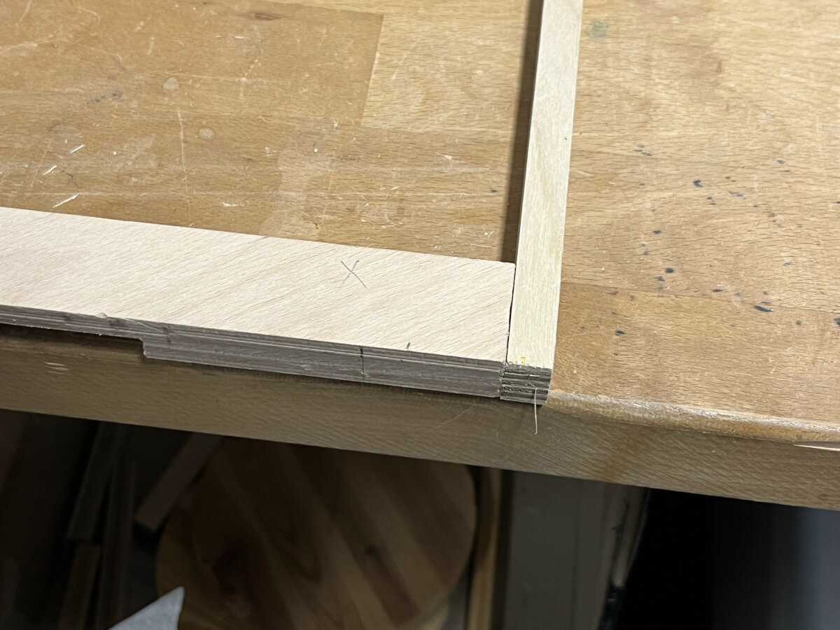
Alignment guide for the first domino slot.
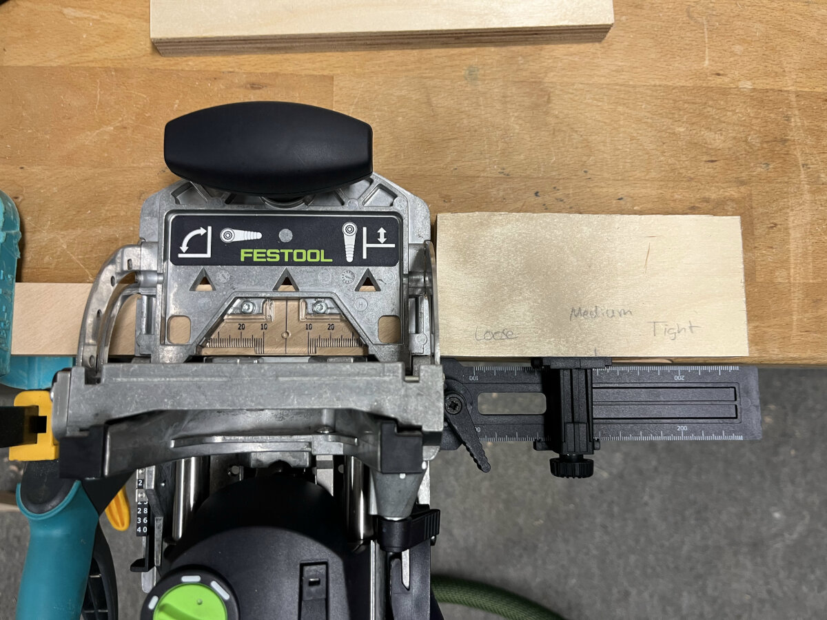
Alignment guide for the second domino slot. Tool: Festool Domino DF 500.
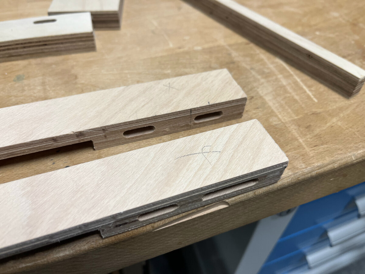
The part in the front was first manufactured without the alignment guide which led to a wide miss aligned mortise which got reworked.
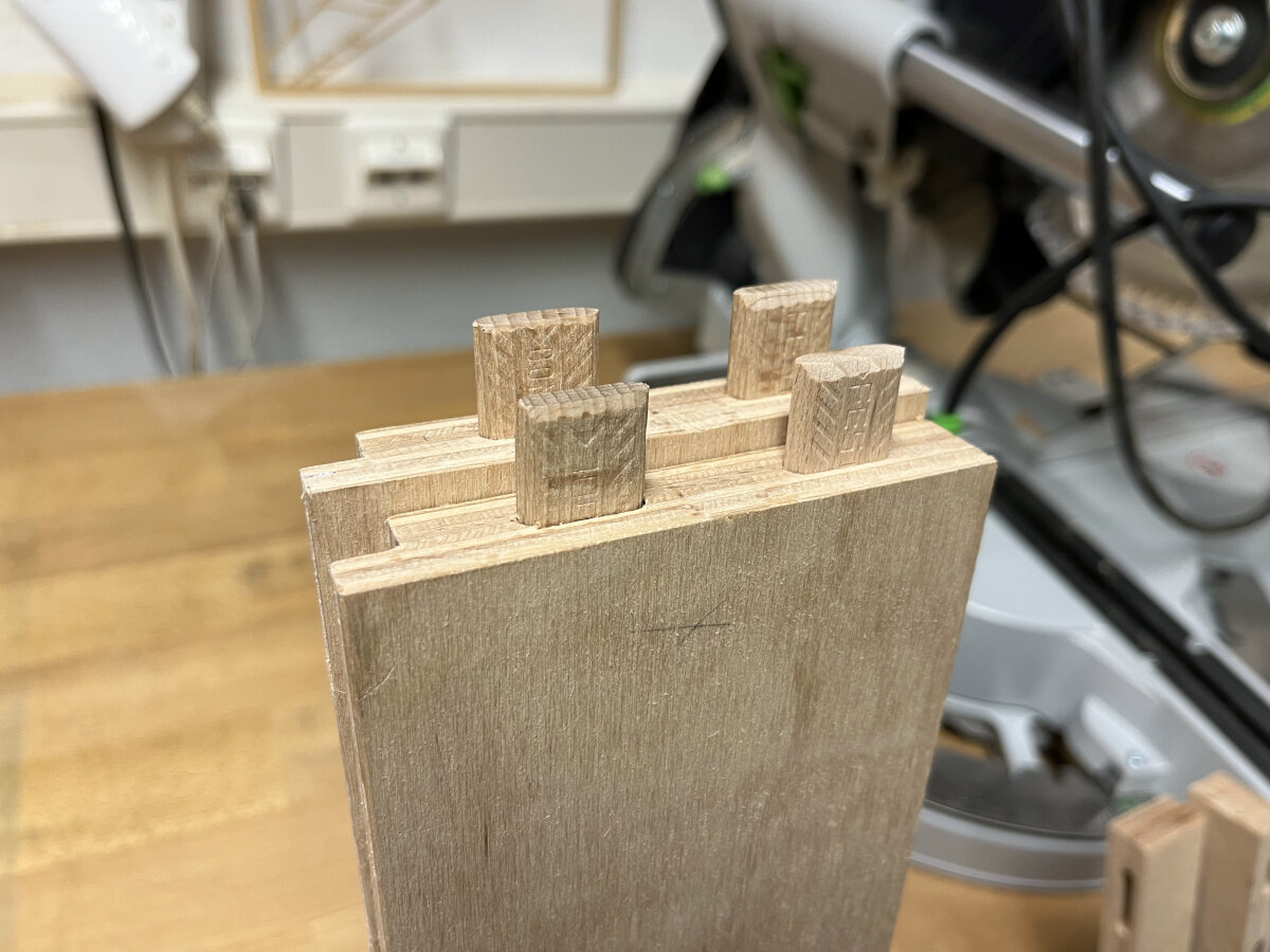
Installed 6 x 40 wooden dominos.
Repair of a surface defect
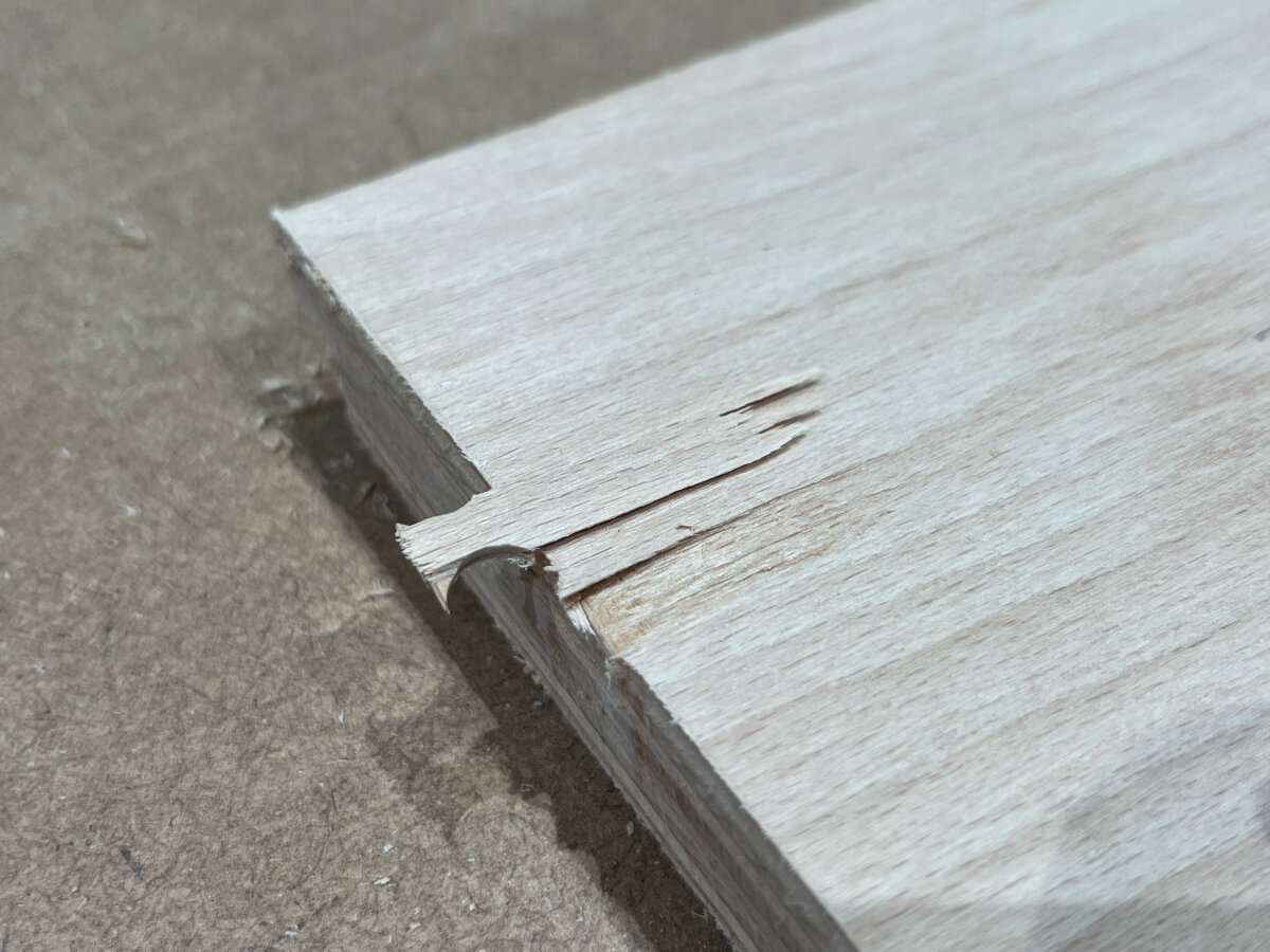
Some of the tabs that are in line with the grain tore off during removal from the stock.
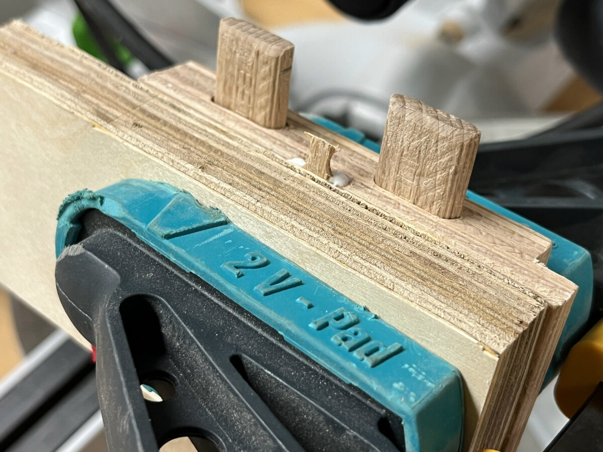
The defect was repaired by reattaching the splitter.
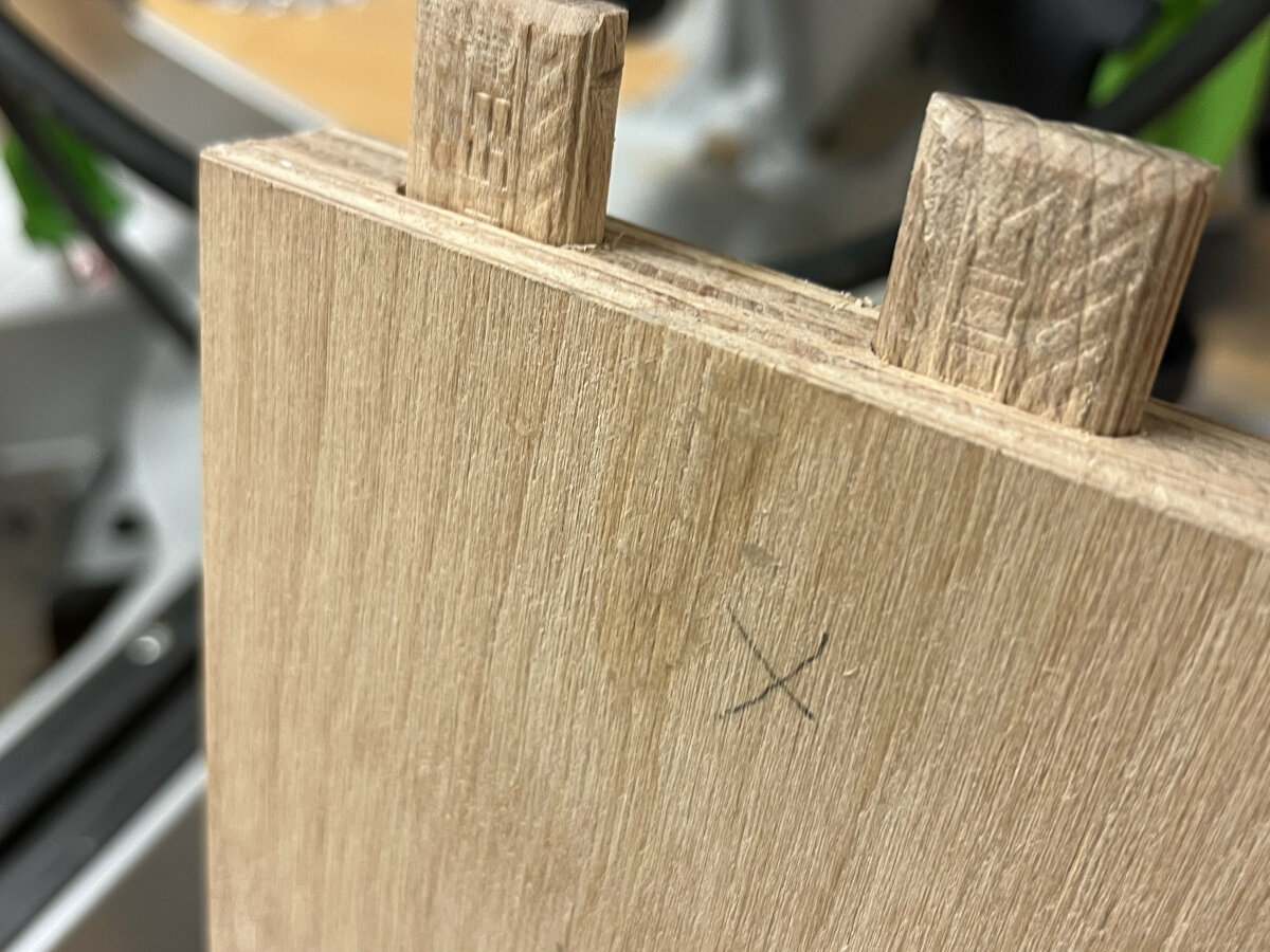
Result of the repaired defect. Almost no marks are visible anymore.
Assembly and Result
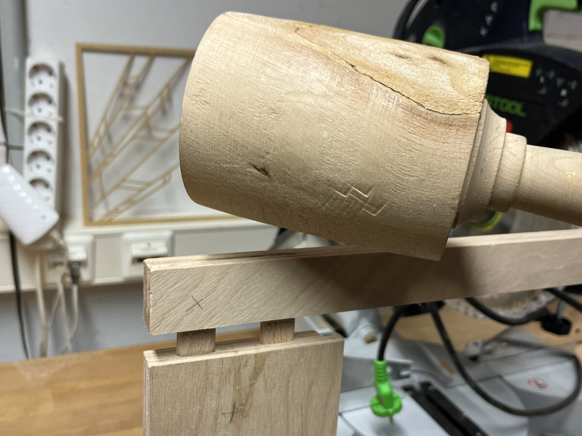
The door frame can be assembled by careful hammering with a wood hammer.
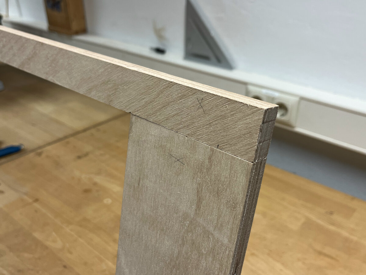
Alignment of the corner after assembly. (Front)
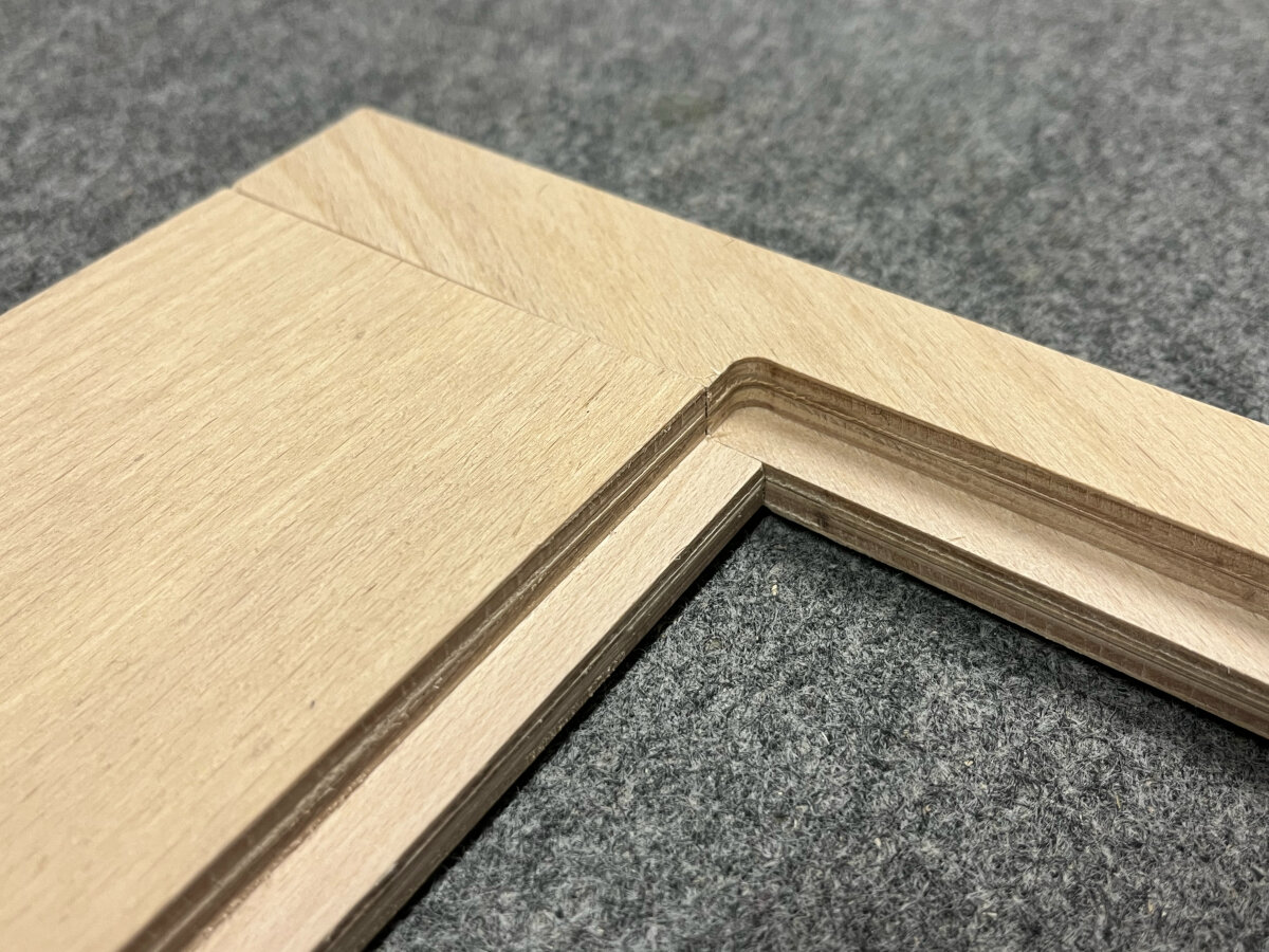
Alignment of the corner after assembly. (Rear)
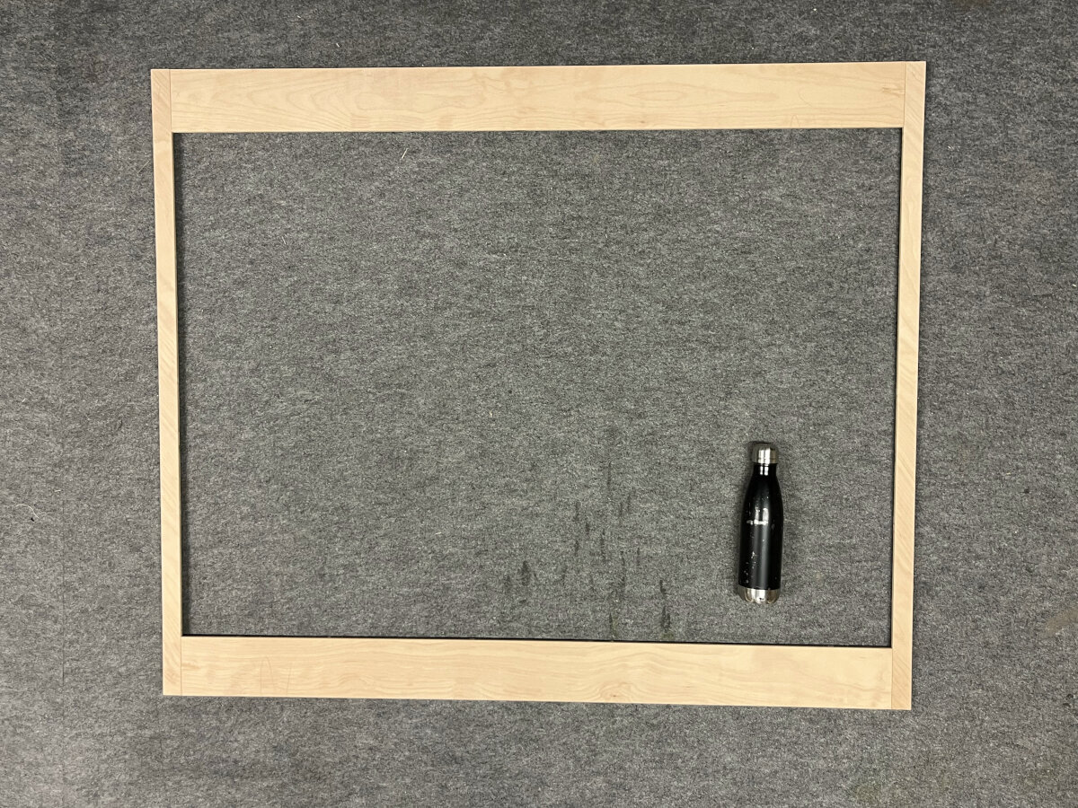
Front of the frame. Water bottle for scale.
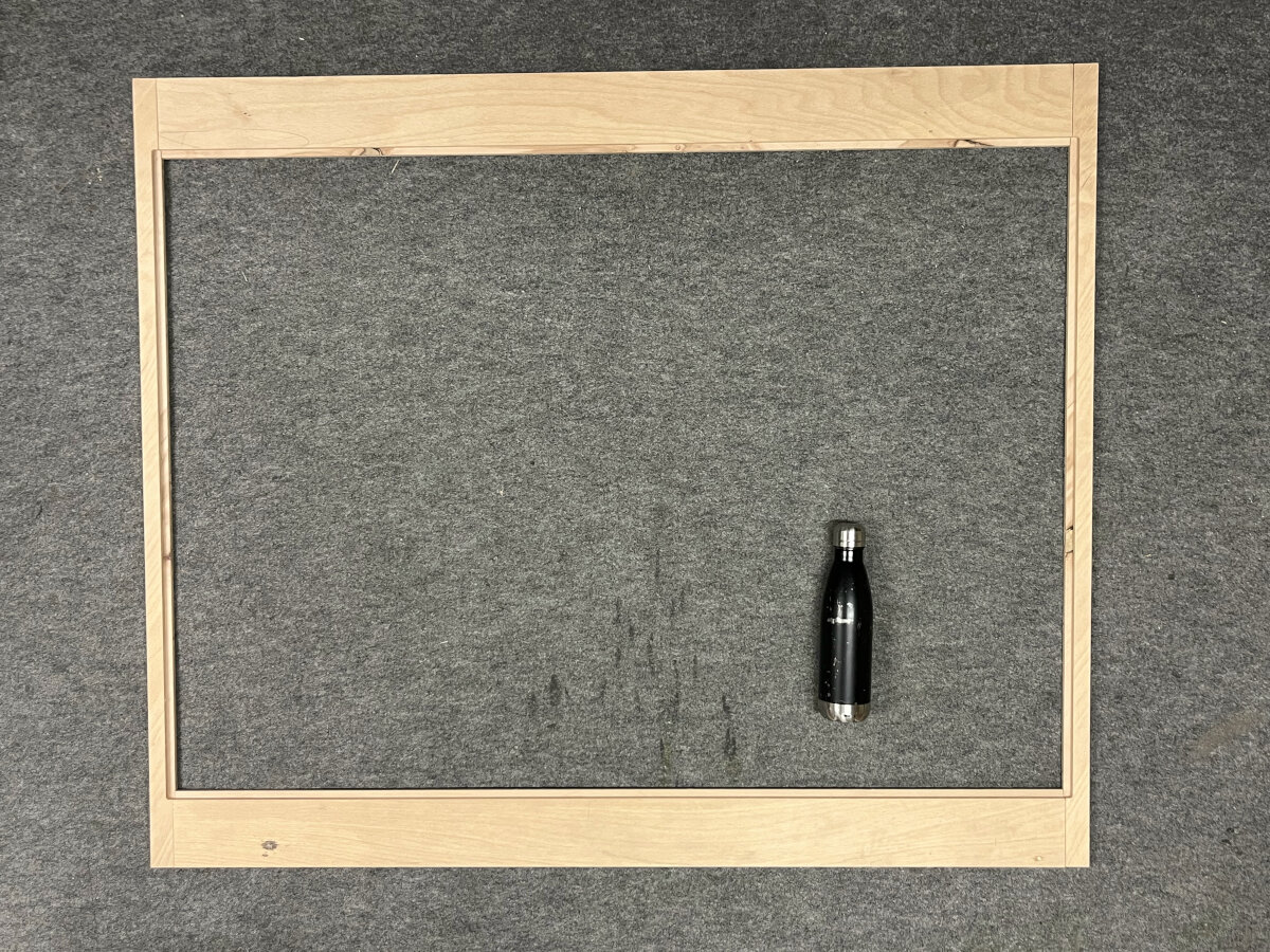
Rear of the frame. Water bottle for scale.
Small CNC: Makera Carvera
Work in Progress
This section is still work in progress. It is an addition to the big mill cnc project to learn more about our the small cnc in our lab.
About Makera
Makera is a Chinese CNC manufacture which was crowdfunded on Kickstarter to create the ultimate CNC for makers with ease of use in mind. Is the word Makera a wordplay to make era?
As the time of writing they are have the following models:
- Makera Carvera (with automatic toolchanger)
- Makera Air (no automatic toolchanger)
- Makera Z1 (harder materials)(currently still on Kickstarter)
Makera CAM
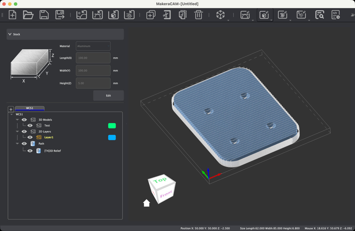
Makera CAM is as the time of writing (Jan. 2026) still in the public beta phase and was launched on february 27th 2025 for the full CAM version.
I was super excited to try out the in-house solution from Makera since I usually enjoy it when a machine manufacturer creates software and hardware with the ease of use in mind.
Install
The installation is quite straight forward. Mac and Windows are supported. Download Makera CAM here.
Documentation
First steps
.stl files can only be used to produce reliefs since the individual faces of the part can only be identified when the geometry is imported as .step
Shortcuts:
- A Select
- X Rotate
- W Pan
- Z Zoom
First Aluminum piece
For my first aluminum milling project, I decided to build a stronger version of a baseplate for my wireless charger. A while ago I already designed and produced a simple non-magnetic wireless charger with a wooden lid top that can be fined in our Unikat project gallery - Wireless Charger.
The goal of my first aluminum milling part was to replace the 3D printed PETG baseplate with a stronger aluminum part. Old part on the left, wooden charger top on the right.

For the milling version, I needed to slightly redesign the part since some elements can't be manufactured subtractive. Because sharp in the corners are impossible with a flute end mill on a tree axis machine.
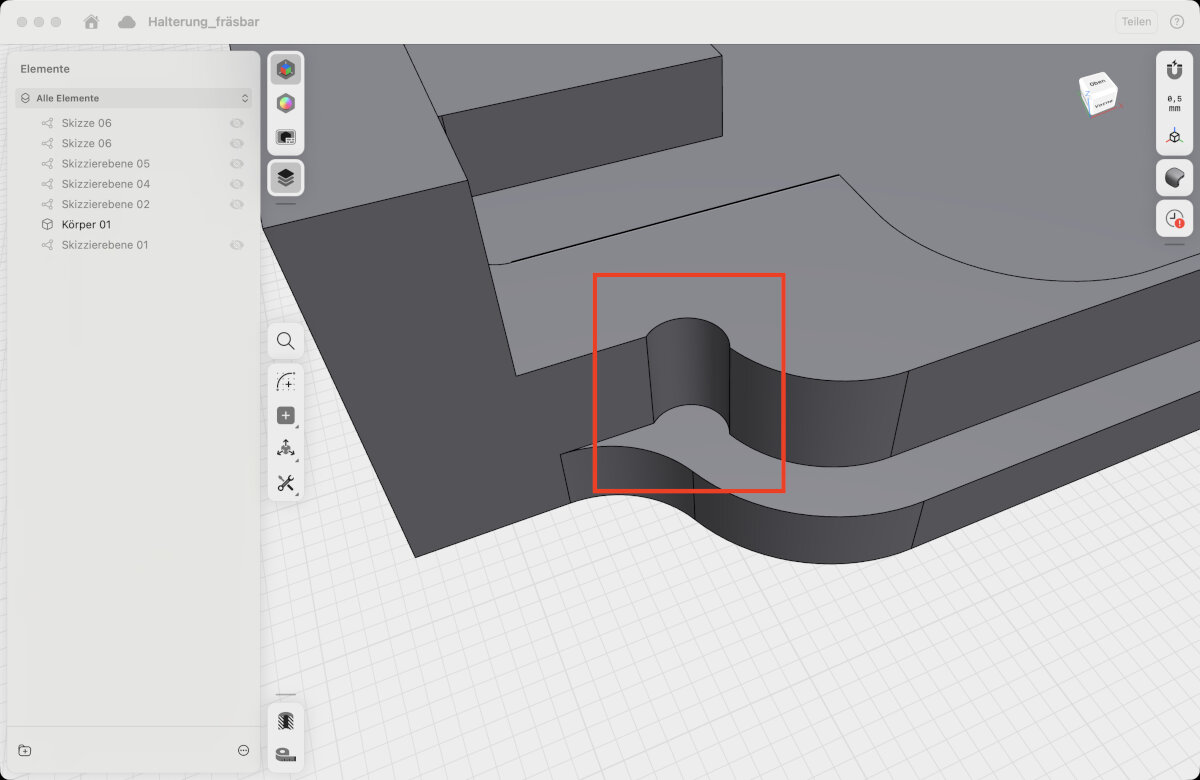
I exported the file as a .step WirlessCharger_baseplate_milling.step file form Shapr3D. Then I imported the object to MakeraCAM.
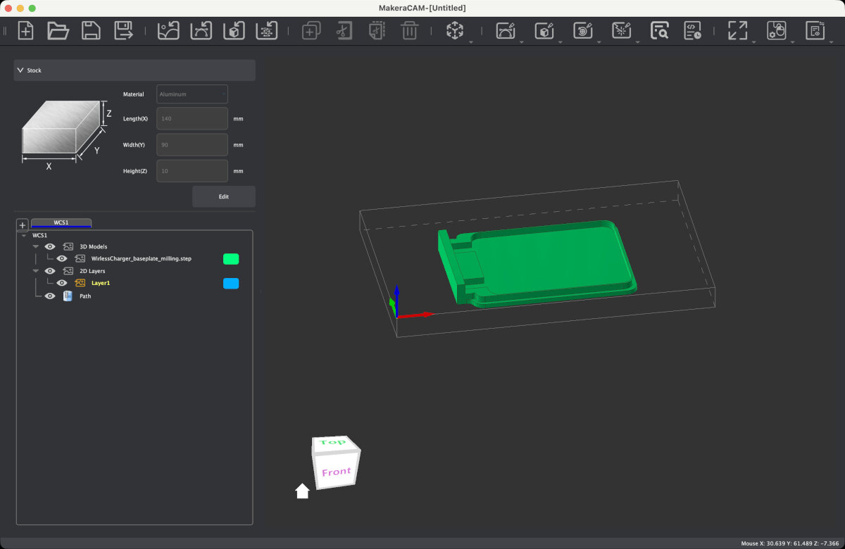
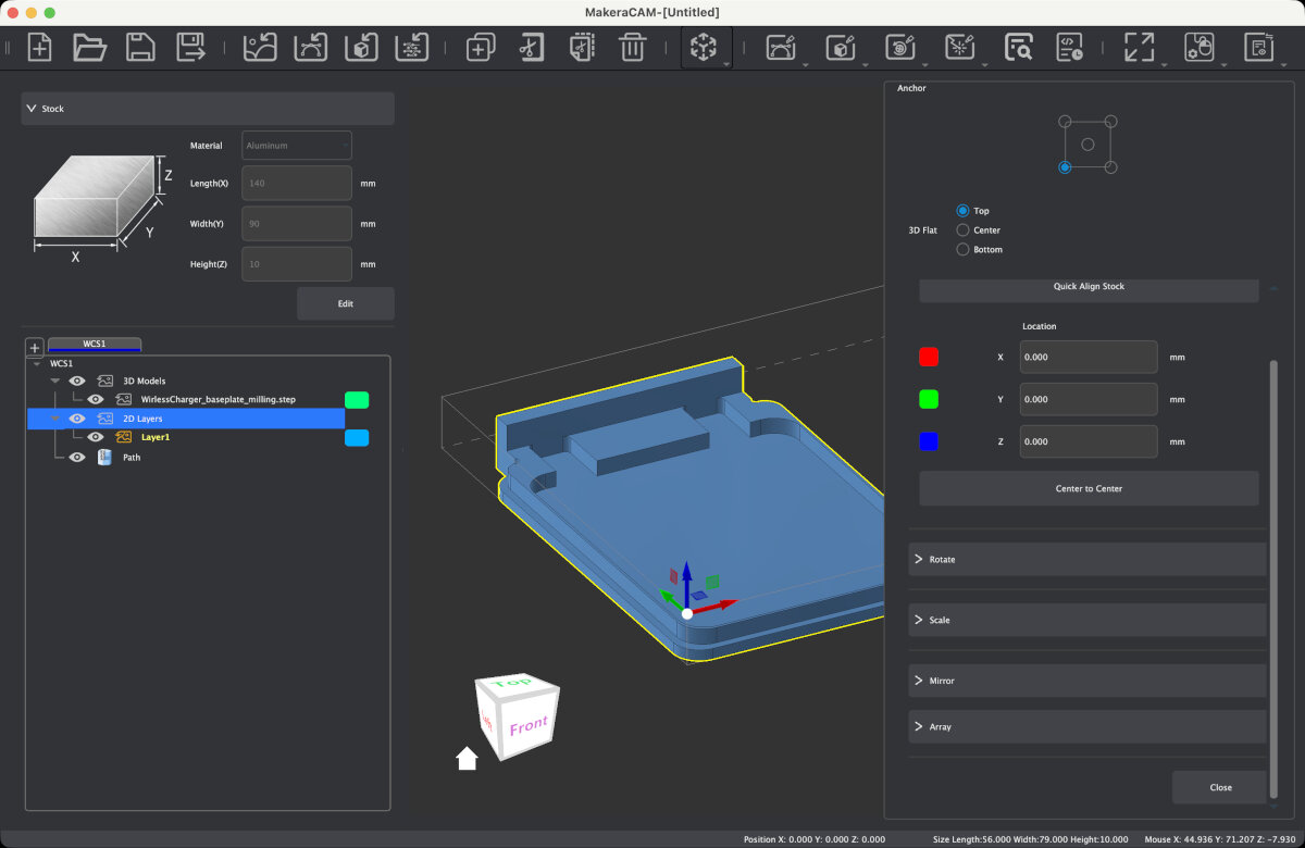
I adjusted the position in my stock.
© 2026 Richard Draxler – Creative Commons Attribution Non Commercial
Source code hosted at gitlab.fabcloud.org