10. Output Devices
view checklists
- Checklist: personal
- DeepL check spelling, grammar
- GPTcheck for better markdown
- Checklist: Nueval:
- Linked to the group assignment page.
- Documented what you learned from interfacing an input device(s) to your microcontroller and optionally, how the physical property relates to the measured results.
- Documented your design and fabrication process or linked to the board you made in a previous assignment.
- Explained the programming process(es) you used. Explained any problems you encountered and how you fixed them.
- Included original design files and source code.
- Included a 'hero shot of your board.
Group assignment
Here is the link to the group assignment about Output Devices.
PWM Dimming - Individual Assignment
Resources
- Electrical Engineering Stackexchange - How to use right PWM frequency for LED?
- Texas Instruments - Dimming Methods: PWM Dimming
- Quinled - How to dim an LED!
- Analog Applications Journal - MOSFET power losses and how they affect power-supply efficiency
Basic Concept of PWM Dimming
The basic concept of PWM dimming is simple. Quickly switching LEDs on and off creates the perception of dimmed brightness levels if done quick enough.
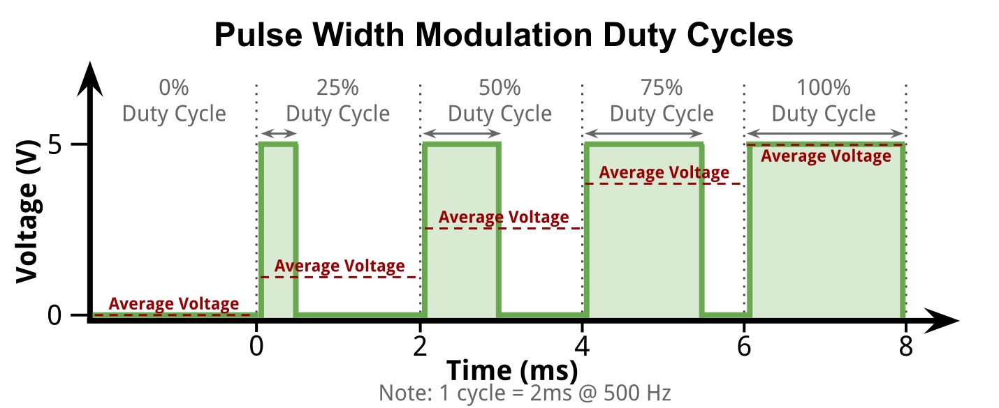
Source: Quinled - How to dim an LED!
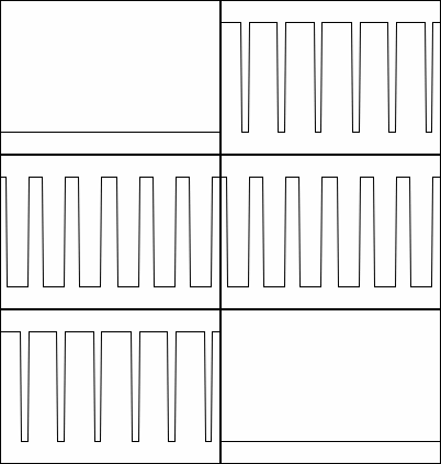
Dimming LEDs by changing the current flowing through the diode is possible, but the emitted color might shift, and the LED might operate at lower efficiency levels when driven with lower the optimal current.
When PWM is used to dim the LED the diode stays at its optimal operation (voltage, current) point, but it is just switched on and off. When it is switched on it operates under optimal conditions allowing for maximum efficiency and correct color emission.
Limits and drawbacks of PWM Dimming
Often PWM dimming can be perceived by the human as disturbing if it is not done in the right way. To low frequencies can lead to eye fatigue, headache or miss operation of equipment. The minimum frequency depends on a couple of factors, some of them are listed below.
- Personal perception, sensitivity to flickering
- Environment conditions (e.g. other light sources)
- Position of the light source in the observers' field of view
- Movement of the observer
- Movement of the light source
These are the factors which I took into consideration for the LUEDO lamp. On the technical side of things there are the electrical limits of the circuit, some of them are listed below.
- Switching losses
- Switching speed (LED and MOSFET)
- Turn-On Delay Time
- Rise Time
- Turn-Off Delay Time
- Fall Time
- Switching noise (perceived as high pitch noise)
After reading into the basics PWM, I decided to set up a couple of experiments to learn more about driving LEDs with PWM.
Goal of the Experiments
The goal for this week's assignment is to learn more about LEDs as output devices. The main focus should be the power consumption and the user's perception of different PWM frequencies.
Since the LUEDO lamp will be a battery powered system the power consumption of the ATtiny and its peripherals is important. Therefore, I have designed a couple of experiments to gain more knowledge of my system.
Below are the parameters that I wanted to measure and the experiments that I wanted to perform.
Design of the Experiments
Power Consumption (@5V)
Analyze the power consumption of the system.
- ATtiny idle with empty loop function
- ATtiny with white LEDs turned on with 50% power using 'analogWrite()'
-
ATtiny with white LEDs turned on, PWM at different frequencies
-
Analyze the power consumption of the system
- measure power consumption
- ATtiny
- TP4056 without battery
Visual and Audible Perception (@5V, 50% Duty Cycle)
Analyze how the user perceives flickering of the PWM driven light source.
Frequency range and steps:
- 20 Hz - 200 Hz in 10 Hz steps
- 200 Hz - 1000 Hz in 100 Hz steps
- 1 kHz - 15 kHz in 1 kHz steps
- 20 kHz - 100 kHz in 10 kHz steps
- 100 kHz - 500 kHz in 100kHz steps
- 1K to 15k audible switching might be noticeable
By doing prior research, I found that the industry standard for PWM dimming of cheap LED light sources is 300Hz.
For all the following experiments and code examples the MainBoard_V01 with the LightBoard_V02 was used. For the experiments only the white LEDs were used. The users' frequency sensibility will most likely depend on the color as well, but for simplicity reasons only the white led array was tested.
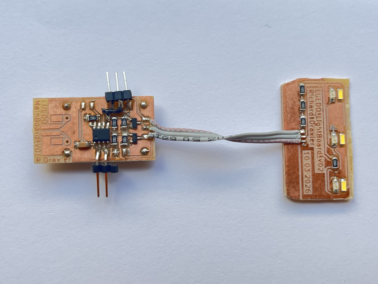
LUEDO MainBoard_V01 with LigthBoard_V02 without SensorBoard.
NOTE: One the back of the MainBoard is a TP4056 LiPo to USB-C board. All tests were performed with the USB-C unplugged and without the battery. Power was provided via the Arduino programmer's +5V and GND rails.
LUEDO LightBoard_V02
The board was manufactured with the Carvera CNC mill and stuffed with components by hand. The soldering was done manually with the soldering iron.
LUEDO_LightBoard_V02_traces.png
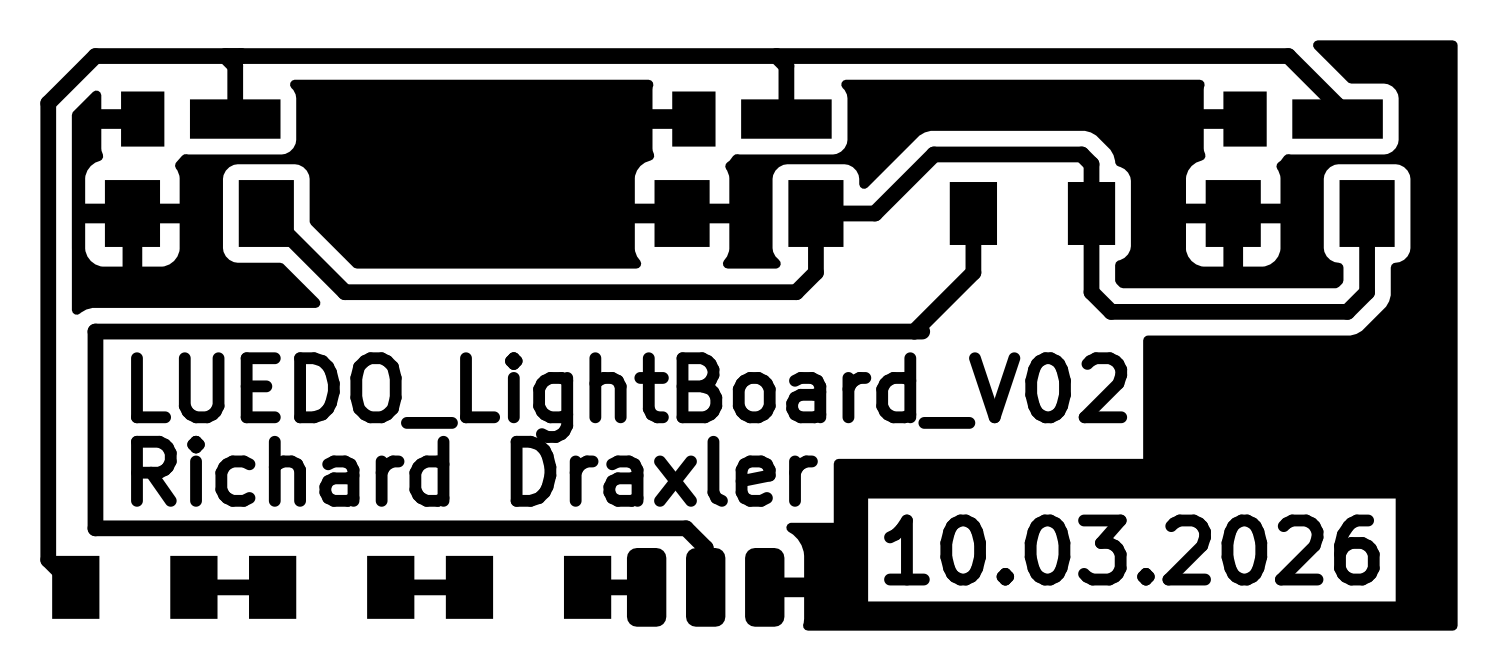
LUEDO_LightBoard_V02_EdgeCut.png

Luedo_LightBoard_V02_d0.2_d0.8.nc
Implementation of PWM Dimming
PWM dimming implementation with analog pins
Arduinos and the ATtiny platform have pins that are marked with "~" to idicate thier analog output ability. This analog output is in reality a PWM digital output that can be controlled with the command analogWrite(pin, value). This PWM signal is preconfigured and can not be easily modified in frequency and duty cycle.
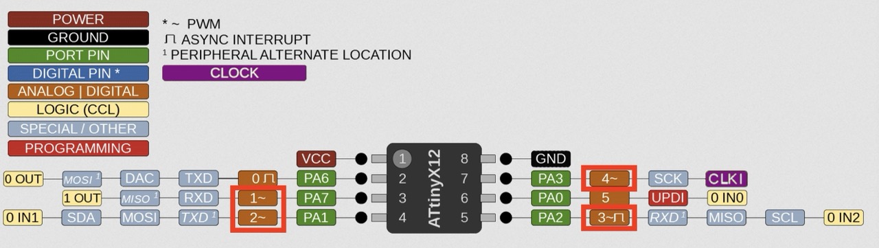
The frequency of the PWM signal produced by the analogWrite function is either ~ 495 Hz or ~ 988 Hz depending on the
To gain more control over the timings of the PWM signal it is implemented manually. PWM signals are quite easy since the LED can be switched on and off with the digitalWrite() command. The on and off duration of the LED can be calculated with the following relations.
| Variable Name | Symbol/Calculation | Unit |
|---|---|---|
| Duty Cycle | \(d\) | % |
| Frequency | \(f\) | Hz |
| Period Time | \(T=\frac{1}{f}\) | s |
| Time On | \(t_{on}=T*\frac{d}{100}\) | s |
| Time Off | \(t_{off}=1-(T*\frac{d}{100})\) | s |
First Version - up to 500 Hz
The code below establishes a serial connection with the ATtiny board. The serial connection is used to display the parameters \(T\), \(t_{on}\) and \(t_{off}\) calculated by the ATtiny. To convert the results of the PWM timing calculation a (int) is used to convert the result from a floating point number to an integer.
Expand Code: MainBoard_V01_PWM_brightness
// ATtiny412
// Communication Pin
const int txPin = 0;  // PA6: TX pin
const int rxPin = 1;  // PA7: RX pin


// Output pins
const int ledPinW = 2;  // PA1: white LED pin
const int ledPinR = 3;  // PA2: red LED pin

// PWM variables
const int dCycl = 3;  // duty cycle in percent, value between 0 and 100
const int f = 200;   // frequency in Hz

int T = 0;
int t_on = 0;
int t_off = 0;


void setup() {
// Configure input pins:
pinMode(ledPinW, OUTPUT);
pinMode(ledPinR, OUTPUT);

Serial.begin(9600);
Serial.setTimeout(100);    // sets the communication timeout to 10ms
Serial.println("ATtiny412 PWM brightness test started!");
Serial.println("Serial connection stared; 9600 baud");

T = (int)(1000.0/f);  // division with conversion to an integer
Serial.print("The period duration T is:");
Serial.println(T);

t_on = (int)(T * (dCycl/100.0));
Serial.print("The time on t_on is:");
Serial.println(t_on);

t_off = (int)(T * (1.0-(dCycl/100.0)));
Serial.print("The time off t_off is:");
Serial.println(t_off);

}

void loop() {
digitalWrite(ledPinW, HIGH);
delay(t_on);
digitalWrite(ledPinW, LOW);
delay(t_off);
}
Range: 32 - 500 Hz
This version of the code has the issue, that the calculated time is only in \(ms\) and not in \(\mu s\) therefore frequencies above 500 Hz (@50% duty cycle) can not be handled since \(t_{on}\) and \(t_{off}\) are 1 ms.
Second Version - up to 50kHz
The var integer only can store values from -32'768 to 32'767, for that reason an intervall shorter than 1 ms can not be stored. To represent frequencies above 500 Hz the time needs to be stored in microseconds and the delay() function needs to be changed to delayMicroseconds(). For the microseconds approach the theoretical maximum frequency would be 50kHz @50% duty cycle, but the number 50'000 cant be stored in an integer, therefore the switch to a long is necessary (-2,147,483,648 to 2,147,483,647).
Expand Code: MainBoard_V01_PWM_brightness_highFreq
// ATtiny412
// Communication Pin
const int txPin = 0;  // PA6: TX pin
const int rxPin = 1;  // PA7: RX pin


// Output pins
const int ledPinW = 2;  // PA1: white LED pin
const int ledPinR = 3;  // PA2: red LED pin

// PWM variables
const int dCycl = 10;  // duty cycle in percent, value between 0 and 100
const long f = 50000;   // frequency in Hz

int T = 0;
int t_on = 0;
int t_off = 0;


void setup() {
// Configure input pins:
pinMode(ledPinW, OUTPUT);
pinMode(ledPinR, OUTPUT);

Serial.begin(9600);
Serial.setTimeout(100);    // sets the communication timeout to 10ms
Serial.println("ATtiny412 PWM brightness test started!");
Serial.println("Serial connection stared; 9600 baud");

T = (int)(1000000.0/f);  // division with conversion to an integer
Serial.print("The period duration T is:");
Serial.println(T);

t_on = (int)(T * (dCycl/100.0));
Serial.print("The time on t_on is:");
Serial.println(t_on);

t_off = (int)(T * (1.0-(dCycl/100.0)));
Serial.print("The time off t_off is:");
Serial.println(t_off);

}

void loop() {
digitalWrite(ledPinW, HIGH);
delayMicroseconds(t_on);
digitalWrite(ledPinW, LOW);
delayMicroseconds(t_off);
}
Range: 32 - 500000 Hz
This version of the code has the issue, that the lower limit of the frequency is 32 Hz since the variable type int can only handle up to ~32k (\(t_{on}\) and \(t_{off}\) surpass the int size restriction). Therefore, changing the variable to an unsigned long will enable a wider range of frequencies.
Third Version - serial control via the PC
To ease the final experiments, I decided to implement a serial connection to my PC. With that I want to be able to change the important parameters as:
- Frequency (\(f\))
- Duty Cycle (\(d\))
- Color (white or red)
The implementation of a serial connection overlaps with the assignment "Interfaces and Application Programming". Therefore, I worked on that assignment first to learn how to set up a serial connection between my ATtiny board and the PC. The process can be found here.
With the learnings form the serial communication between PC and the ATtiny board, I wrote the code below. It is for sure not an efficient implementation, but it works.
Controlling the board via CoolTerm Serial Monitor: changing the PWM frequency.
Controlling the board via CoolTerm Serial Monitor: changing the duty cylce.
Controlling the board via CoolTerm Serial Monitor: changing the emitted light color.
Expand Code: MainBoard_V01_PWM_brightness_serial
// ATtiny412

// Output pins
byte ledPin = 0;         // variabel for switching between pins
const byte ledPinW = 2;  // PA1: white LED pin
const byte ledPinR = 3;  // PA2: red LED pin

// PWM variables
unsigned long f = 0;   // frequency in Hz
byte dCycl = 0;  // duty cycle in percent, value between 0 and 100
byte color = 0;  // 0 represents red, 1 represents white
unsigned int T = 0;
unsigned int t_on = 0;
unsigned int t_off = 0;

void setup() {
// Configure input pins:
pinMode(ledPinW, OUTPUT);
pinMode(ledPinR, OUTPUT);

Serial.begin(9600);
Serial.setTimeout(100);    // sets the communication timeout to 10ms
Serial.println("ATtiny412 PWM brightness test started!");
Serial.println("Serial conn. stared; 9600 baud");
}

//Variables
const byte numChars = 32;
char receivedChars[numChars];   // an array to store the received data

boolean newData = false;        // indicator if data is arriving

int dataNumber;                 // placeholder for the integer that is created form the char array
long dataNumberL;               // placeholder for the long that is crated from the char arry


//Functions
void recvWithEndMarker(){
static byte ndx = 0;
char endMarker = '\n';
char rc;

if (Serial.available() > 0) {
    rc = Serial.read();

    if (rc != endMarker) {
    receivedChars[ndx] = rc;
    ndx++;
    if (ndx >= numChars) {      // reduce ndx by one to make sure, it jumps to the else part in the next function call
        ndx = numChars -1;
    }
    }
    else {
    receivedChars[ndx] = '\0';  // terminate the string
    ndx = 0;                    // reset the char index variable to 0
    newData = true;
    }
}
}

//void convertToInt() {
//  if (newData == true) {
//    dataNumber = 0;
//    dataNumber = atoi(receivedChars);
//    //Serial.println("Char array converted to integer");
//    newData = false;
//  }
//}

void convertToLong() {
if (newData == true) {
    dataNumberL = 0;
    dataNumberL = atol(receivedChars);
    //Serial.println("Char array converted to integer");
    newData = false;
}
}


void calcPWM(){ //calPWM calculates the PWM values, this function needs no input and has no output. It is using the global variables
T = (unsigned int)(1000000.0/f);  // division with conversion to an integer, T in mikroseconds

t_on = (unsigned int)(T * (dCycl/100.0));

t_off = (unsigned int)(T * (1.0-(dCycl/100.0)));

Serial.print(" -> PWM:[ ");
Serial.print("f:");Serial.print(f);Serial.print(" Hz");
Serial.print(" | T:");Serial.print(T);Serial.print(" µs");
Serial.print(" | t_on:");Serial.print(t_on);Serial.print(" µs");
Serial.print(" | t_off:");Serial.print(t_off);Serial.print(" µs");
Serial.print(" ]");
}

void askFreq(){
    Serial.println("Input freq. in Hz");
    while (newData == false) {
    recvWithEndMarker();
    }
    convertToLong();
    f = dataNumberL;
    Serial.print(" -> f: ");
    Serial.println(f);
}

void askDCycl(){
    Serial.println("Input duty cycle in %");
    while (newData == false) {
    recvWithEndMarker();
    }
    convertToLong();
    dCycl = (byte)dataNumberL;
    Serial.print(" -> dCycl: ");
    Serial.println(dCycl);
}

void askColor(){
    Serial.println("Input led color white or red [0/1]");
    while (newData == false) {
    recvWithEndMarker();
    }
    convertToLong();
    color = (byte)dataNumberL;
    Serial.print(" -> color: ");
    if (color == 0) {
    ledPin = ledPinW;
    Serial.println("w");
    }
    if (color == 1) {
    Serial.println("r");
    ledPin = ledPinR;
    }
}

void pwmOutput(){
    digitalWrite(ledPin, HIGH);
    delayMicroseconds(t_on);
    digitalWrite(ledPin, LOW);
    delayMicroseconds(t_off);
}

void loop() {
askFreq();
askDCycl();
askColor();

calcPWM();
while (true){   //endless loop
    while (newData == false) {
    recvWithEndMarker();
    pwmOutput();
    }
    //Serial.println("debug");
    Serial.print(receivedChars);
    if (receivedChars[0] == 'f'){   //check for first character in the char array, Position zero! not one
    newData = false;
    askFreq();
    calcPWM();
    }
    if (receivedChars[0] == 'd'){   //check for first character in the char array, Position zero! not one
    newData = false;
    askDCycl();
    calcPWM();
    }
    if (receivedChars[0] == 'c'){   //check for first character in the char array, Position zero! not one
    newData = false;
    askColor();
    }
    }
}
In the third iteration a couple of improvements were made:
- reduced variables to efficient sizes (e.g. byte for the duty cycle (0-100) range)
- change integers to unsigned integers to expand the range
- minimum frequency: 16Hz, maximum frequency: 50kHz
- added the ability to change values after starting the sketch
- Frequency
- Duty Cycle
- Color
Minimal frequency 16Hz
For some reason the minimal frequency is 16Hz for the code above. I have not found the issue why lower frequencies are not possible.
Recorded Data
ATtiny_LED_PWM_20Hz-20kHz.xlsx
Data Analysis
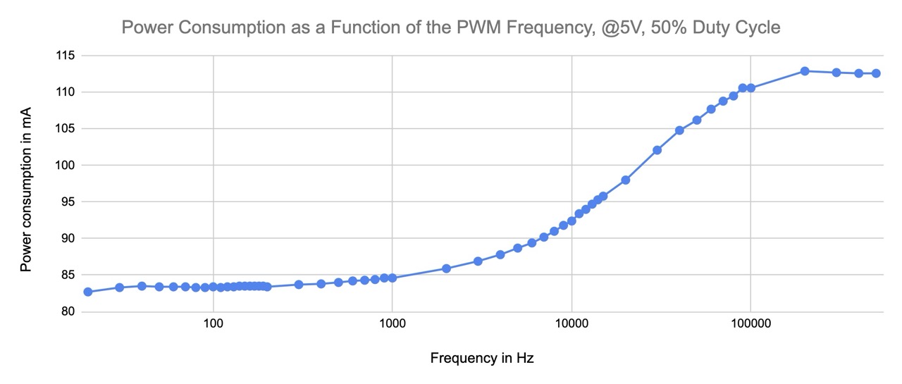
Power consumption of the LUEDO MainBoard_V01 with LightBoard_V02. Frequency: variable, Duty Cycle: 50%, Color: White
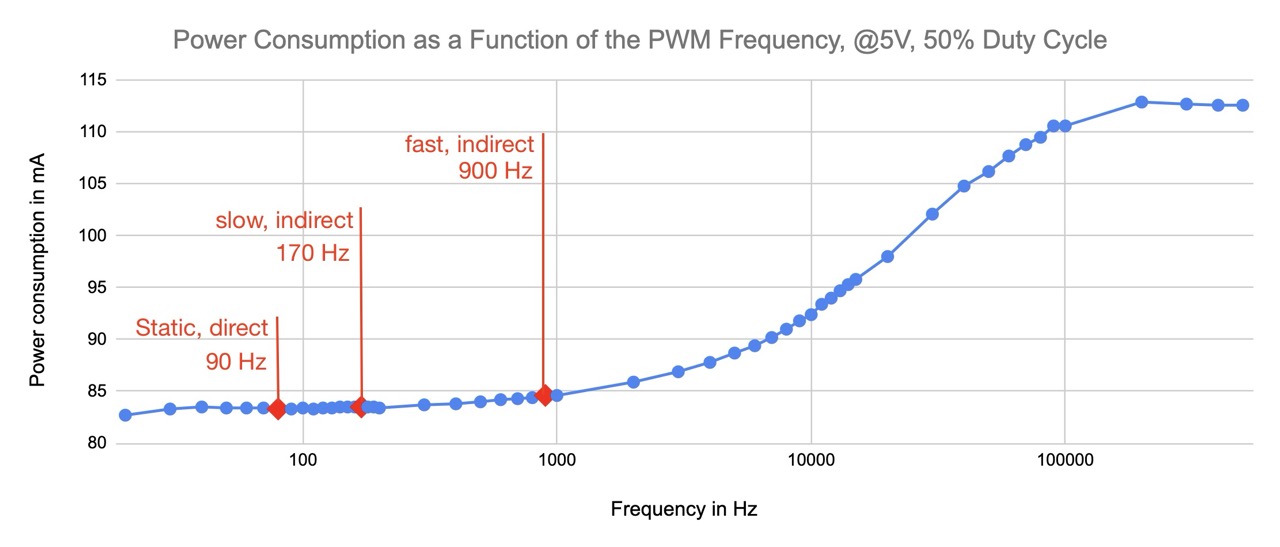
Frequencies at which flickering of a light source cant be perceived anymore.
At these points I personally can't perceive any flickering of the light source anymore.
- Direct look into the light source (direct), no movement
- Observing a slow moving object that is illuminated by the LEDs (indirect)
- Observing a fast moving object that is illuminated by the LEDs (indirect)
Personal perception is different
Everyone perceives light differently. The term 'slow' and 'fast' moving objects were not precisely defined and should not be treated as a scientific analysis rather than a first design guide for the LUEDO prototype. The goal of the experiment was to find a sutiable. reference frequency for further development steps.
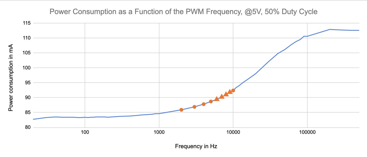
High pitch sounds caused by PWM switching.
Circle marker - noticeable; Triangle marker - noticeable and annoying
Result
- To keep the switching losses low, frequencies below 1000Hz should be used for the PWM
- Frequencies of 900 Hz and above can be used for fast moving objects without flickering reception
-
Frequencies below 2000Hz or above 10'000Hz should be used to eliminate switching noise
→ Suitable frequency range: 900-1000 Hz
Learnings
- ATtiny 412 storage is tiny!
- Long 'println()' CLI like interfaces take up too much space
- using the smallest variable type possible is necessary
- a safe CLI user input is not as straight forward as I though
- hard to trace errors can accrue when values with wrong length or format are passed to a variable
© 2026 Richard Draxler – Creative Commons Attribution Non Commercial
Source code hosted at gitlab.fabcloud.org