11. Embedded Networking and Communications
Checklists
Checklist: personal
- DeepL check spelling, grammar
- GPTcheck for better markdown
- repair file links, replace .png -> .jpg; .mov -> .mp4
- repair file links, replace .HEIC -> .jpg
- link to Jarnis page
Checklist: Nueval: Student's checklist
- Linked to the group assignment page
- Documented your project and what you have learned from implementing networking and/or communication protocols.
- Explained the programming processes you used.
- Ensured and documented that your addressing for boards works
- Outlined problems and how you fixed them.
- Included design files (or linked to where they are located if you are using a board you have designed and fabricated earlier) and original source code.
- Included a 'hero shot' of your network and/or communications setup
Group Assignment
Here is our labs group assignment page.
I did the group assignment with Jarni together. We chose to use the Seed Studio XIAO ESP32-S3 basic version (no sense, no plus) and wirelessly communicate between nodes.
ESP-NOW Protocol
ESP-NOW is a protocol that is based on the Wi-Fi standard, which works without an intermediate router. It is designed primarily for IoT devices to enable low power communication between microcontrollers. It establishes a connection between two nodes and sends messages between them. The range of the connection can be up to 30 m if no blocking objects are between the nodes.
To establish a connection between the nodes in the ESP NOW network the following steps are needed.
Find ESP MAC address
Upload the script to the ESP32 and open the Arduino serial monitor. Copy the MAC address from the serial monitor and paste it into the Node2_ESP_NOW script in the header.
View Code: check_MAC
#include <WiFi.h>
#include <esp_wifi.h>

void setup() {
Serial.begin(115200);
WiFi.mode(WIFI_STA);
delay(100);

uint8_t mac[6];
esp_wifi_get_mac(WIFI_IF_STA, mac);
Serial.printf("MAC STA: %02X:%02X:%02X:%02X:%02X:%02X\n",
                mac[0], mac[1], mac[2], mac[3], mac[4], mac[5]);
}

void loop() {}
We flashed this code on a couple of ESPs that we had in our lab. Here are two examples of MAC addresses from our ESPs.
ESP32S3:             74:4D:BD:96:D5:58
ESP32 Dev Module:    A8:42:E3:91:6F:9C
ESP NOW Button and LED
For the ESP NOW communication this script below is used to
View Code: Node2_ESP_NOW
#include <WiFi.h>
#include <esp_now.h>

#define LED_PIN 7          // LED connected to GPIO 7
#define BUTTON_PIN 3       // Button connected to GPIO 3

// MAC address of the other ESP32-S3
uint8_t peerAddress[] = {0x64, 0xe8, 0x33, 0x50, 0xb3, 0xa0};
// MAC address of the target ESP32, found with the script "check_MAC", replace with device specific address

// Updated prototype
void OnDataRecv(const esp_now_recv_info_t *recv_info, const uint8_t *data, int len);
    // *recv_info   adds additional information from the sender e.g the MAC address
    // *data        data of the message
    // len          length of the message

bool lastButtonState = false;  // To track button state for edge detection

void setup() {
    Serial.begin(115200);  // Start serial communication at 115200 baud

    pinMode(LED_PIN, OUTPUT);     // Set LED pin as output
    pinMode(BUTTON_PIN, INPUT_PULLUP);  // Button with internal pull-up

    WiFi.mode(WIFI_STA);  // Set Wi-Fi to Station mode (required for ESP-NOW)

    Serial.print("My MAC: ");
    Serial.println(WiFi.macAddress());  // Print this ESP32's own MAC address, check_MAC script is redundant here
    Serial.println(WiFi.macAddress());

    if (esp_now_init() != ESP_OK) {         // If hardware error occurs, setup will be aborted, ESP_OK means success
        Serial.println("Error starting ESP-NOW");
        return;
    }

    //  Callback with new signature
    esp_now_register_recv_cb(OnDataRecv);

    // Add peer (target device)
    esp_now_peer_info_t peerInfo = {};
    memcpy(peerInfo.peer_addr, peerAddress, 6);  // Copy MAC address
    peerInfo.channel = 0;                        // Use channel 0
    peerInfo.encrypt = false;                    // No encryption (for simplicity)

    if (!esp_now_is_peer_exist(peerAddress)) {      // Checks if target device is already registered
        if (esp_now_add_peer(&peerInfo) != ESP_OK) {
            Serial.println("Error adding peer");
            return;
        }
    }

    Serial.println("ESP-NOW configured successfully");
}

// New form of the callback
void OnDataRecv(const esp_now_recv_info_t *recv_info, const uint8_t *data, int len) {
    Serial.print("Message received from: ");
    char macStr[18];
    snprintf(macStr, sizeof(macStr), "%02X:%02X:%02X:%02X:%02X:%02X",
    recv_info->src_addr[0], recv_info->src_addr[1], recv_info->src_addr[2],
    recv_info->src_addr[3], recv_info->src_addr[4], recv_info->src_addr[5]);
    // returns the senders MAC address, six positions get listed and formatted to two characters each
    Serial.println(macStr);
    // Turn on LED in response, confirmation: message received
    digitalWrite(LED_PIN, HIGH);
    delay(200);
    digitalWrite(LED_PIN, LOW);
}

void loop() {
    bool currentButtonState = !digitalRead(BUTTON_PIN); // Button with INPUT_PULLUP

    if (currentButtonState && !lastButtonState) {
    Serial.println("Button pressed, sending message...");
    uint8_t data = 1;
    esp_now_send(peerAddress, &data, sizeof(data));
    }

    lastButtonState = currentButtonState;
}
We iterated the code a couple of times with the help of AI tools. The newer and currently running version improved a couple of things:
- Information about the sender is attached to a message
- Edge detection for button press
- Avoids sending multiple messages when button is pressed longer
- Better reliability, checks if peer already exists
- Just a single byte is sent instead of a string
General operation principle of the code: If the button on node 1 is pressed the first ESP sends a single byte to a fixed target device. The target device is set via the MAC address. If the target e.g. node 2 receives the byte it will turn on its led. Each node displays its actions and own MAC address on the serial monitor if a pc is connected.
Operation of the button press at one of the nodes
Demonstration of the two ESP now sending and receiving signals from each other. Node 1 has a red LED (left), node 2 has a green LED (right).
Individual Assignment
Wired Communication: UART
For the individual assignment I choose to build a simple serial communication between two self-made boards. The first board is the LUEDO DevBoard_V01 to which I attached an additional RX wire (green) since for now the board could only send via TX. As an input device I attached the SensorBoard_V01_A. The second node of my network is the LUEDO MainBoard_V01 with the LightBoard_V02 attached as an output device.
The general idea is that the hall sensor on the first node will read the hall sensor value and decide if the magnetic field is positive, negative, or not existent. Then the value of the magnetic field will be mapped to a light color. This color information will be transmitted via the serial connection to the other node. The second node will pick up the signal and emit the according light color or turn off the LEDs.
To visualize that the communication is not just in one direction but bidirectional, the second node sends back the color information and the first node lights up either the red or white LED.
Node 1: LUEDO DevBoard_V01
The hardware for the node 1 is the LUEDO DevBoard_V1. Its production can be found in the Electronics Production assignment - Week 08
For the first trial I wrote this code snipped for the LUEDO DevBoard_V01. It will send a 0, 1 or 2 via its TX pin. This communication can be easily observed on the computers serial monitor to verify its function.
flowchart LR
    node1["Node 1<br/>(DevBoard)"]
    adapter["Serial<br/>to<br/>USB"]
    pc["PC"]

    node1 -->|"Tx → Rx: color"| adapter

    adapter -->|"USB: read Color"| pc

    classDef device fill:#fff,stroke:#244a9b,stroke-width:2px,color:#111
    class adapter,pc device
    classDef board fill:#fff,stroke#244a9b,stroke-width:5px,color:#111
    class node1 board
View Code: Serial TX color code LUEDO DevBoard_V01
// ATtiny 1624; LUEDO DevBoard_V01

// Communication Pins
const int txPin = 5;  //PB2: Tx pin
const int rxPin = 4;  //PB3: Rx pin

// Input Pins
const int hallPin = 0;

// Variables
int val = 0;          // saves the current hall sensor value
byte color = 0;       // Color variable:
// 0 - off
// 1 - red
// 2 - white

void setup() {
Serial.begin(9600); //starts the serial connection
}

void loop() {
val = analogRead(hallPin);  // store the sensor value in the var val
//Serial.println(val);
if (val >= 600){
    color = 1; //color red
    //Serial.println("red");
}
if (val <= 400){
    color = 2; //color white
    //Serial.println("white");
}
if(val < 600 && val > 400){
    color = 0; //led off
    //Serial.println("off");
}
Serial.println(color);
delay(10);
}
To add the receipt RX functionality to the code I used the serial communication basics that I already added to the Interface and Application Programming Assignment - Week14 assignment. There I sent commands from my computer to the ATtiny board. To achieve that, the ATtiny needs to translate the ASCII characters back to numbers, that can be stored in a variable.
flowchart LR
    node1["Node 1<br/>(DevBoard)"]
    adapter["Serial<br/>to<br/>USB"]
    pc["PC"]

    node1 -->|"Tx → Rx: color"| adapter
    adapter -->|"Rx ← Tx: set color"| node1

    adapter -->|"USB: read Color"| pc
    pc -->|"USB: set Color"| adapter

    classDef device fill:#fff,stroke:#244a9b,stroke-width:2px,color:#111
    class adapter,pc device
    classDef board fill:#fff,stroke#244a9b,stroke-width:5px,color:#111
    class node1 board
View Code: Serial TX/RX color code LUEDO DevBoard_V01
// ATtiny 1624; LUEDO DevBoard_V01

// Input Pins
const int hallPin = 0;

// Output Pins
const int ledPinWhite = 8;  //PA1, white
const int ledPinRed = 9;    //PA2, red


// Variables
int val = 0;          // saves the current hall sensor value
byte color = 0;       // Color variable:
// 0 - off
// 1 - red
// 2 - white
const byte numChars = 32;      // maximal length of received string
char receivedChars[numChars];  // an array to store the received data

boolean newData = false;
int dataNumber;               // the converted number will be stored here

void setup() {
Serial.begin(9600); //starts the serial connection
}

void recvWithEndMarker(){
static byte ndx = 0;    // index of the received characters
char endMarker = '\n';
char rc;                // received character

if (Serial.available() > 0) { //check if the serial connection is present
    rc = Serial.read();

    if (rc != endMarker){
    receivedChars[ndx] = rc;
    ndx++;
    if (ndx >= numChars) {
        ndx = numChars - 1;
    }
    }
    else {
        receivedChars[ndx] = '\0'; // terminate the string
        ndx = 0;
        newData = true;
    }
}
}

void ledControl(){
    if (newData == true) {
        dataNumber = 0;                     // default value is 0
        dataNumber = atoi(receivedChars);   // convertion form char array to int

        Serial.println(dataNumber);         // output the integer

        if (dataNumber == 0){
        analogWrite(ledPinWhite, 0);
        analogWrite(ledPinRed, 0);
        }

        if (dataNumber == 1){
        analogWrite(ledPinRed, 255);
        analogWrite(ledPinWhite, 0);
        }

        if (dataNumber == 2){
        analogWrite(ledPinWhite, 255);
        analogWrite(ledPinRed, 0);
        }
        newData = false;
    }
}

void loop() {
val = analogRead(hallPin);  // store the sensor value in the var val
//Serial.println(val);
if (val >= 600){
    color = 1; //color red
    //Serial.println("red");
}
if (val <= 400){
    color = 2; //color white
    //Serial.println("white");
}
if(val < 600 && val > 400){
    color = 0; //led off
    //Serial.println("off");
}
Serial.println(color);
delay(10);

recvWithEndMarker();
ledControl();
}
The video shows the ability of the code to receive and send signals. This process happens not at the same time but fast enough for this application.
Node 2: LUEDO MainBoard_V01
The hardware for the node 2 is the LUEDO MainBoard_V1. Its production can be found in the Electronics Production assignment - Week 08
The second node is the output and feedback node. Its task is it to recieve the color information and turn on the LEDs on the LUEDO_LightBoard. After turning on the LEDs it will send back the color information to node 1 via its TX terminal. The functionality of node 2 can be easily confirmed with the serial-to-USB adapter and the serial monitor on my computer.
flowchart LR
    pc["PC"]
    adapter["Serial<br/>to<br/>USB"]
    node2["Node 2<br/>(MainBoard)"]

    pc -->|"USB: set color"| adapter
    adapter -->|"Tx → Rx: set color"| node2
    node2 -->|"Rx ← Tx: confirm color"| adapter

    adapter -->|"USB: read color"| pc

    classDef device fill:#fff,stroke:#244a9b,stroke-width:2px,color:#111
    class adapter,pc device
    classDef board fill:#fff,stroke#244a9b,stroke-width:5px,color:#111
    class node2 board
View Code: Node2_MainBoard_ATtiny412
// ATtiny 412, LUEDO MainBoard_V01

// Output Pins
const int ledPinWhite = 2;  // PA1: white LED pin
const int ledPinRed = 3;  // PA2: red LED pin

// Variables
byte color = 0;       // Color variable:
// 0 - off
// 1 - red
// 2 - white
const byte numChars = 32;      // maximal length of received string
char receivedChars[numChars];  // an array to store the received data

boolean newData = false;
int dataNumber;               // the converted number will be stored here

void setup() {
Serial.begin(9600); //starts the serial connection
}

void recvWithEndMarker(){
static byte ndx = 0;    // index of the received characters
char endMarker = '\n';
char rc;                // received character

if (Serial.available() > 0) { //check if the serial connection is present
    rc = Serial.read();

    if (rc != endMarker){
    receivedChars[ndx] = rc;
    ndx++;
    if (ndx >= numChars) {
        ndx = numChars - 1;
    }
    }
    else {
        receivedChars[ndx] = '\0'; // terminate the string
        ndx = 0;
        newData = true;
    }
}
}

void ledControl(){
    if (newData == true) {
        dataNumber = 0;                     // default value is 0
        dataNumber = atoi(receivedChars);   // convertion form char array to int

        if (dataNumber == 0){
        analogWrite(ledPinWhite, 0);
        analogWrite(ledPinRed, 0);
        Serial.println(dataNumber);
        }

        if (dataNumber == 1){
        analogWrite(ledPinRed, 30);     // 30 to limit the LED brightness
        analogWrite(ledPinWhite, 0);
        Serial.println(dataNumber);
        }

        if (dataNumber == 2){
        analogWrite(ledPinWhite, 5);    // 5 to limit the LED brightness
        analogWrite(ledPinRed, 0);
        Serial.println(dataNumber);
        }
        newData = false;
    }
}

void loop() {
recvWithEndMarker();
ledControl();
}
Node1-to-Node2 Serial Communication
The code for this section is listed in the two sections above specific to each board.
flowchart LR
    node1["Node 1<br/>(DevBoard)"]
    node2["Node 2<br/>(MainBoard)"]


    node1 -->|"Tx → Rx: set color"| node2
    node2 -->|"Rx ← Tx: confirm color"| node1

    classDef board fill:#fff,stroke#244a9b,stroke-width:5px,color:#111
    class node1,node2 board
Bug: Return of color not working
In the current version of the code of node 2 or node 1 is some kind of bug in the return communication. Sending the signal from node 1 to node 2 works without any issues, but the return path is broken for some reason. I suspect the bug is related to the fromat infromation sent e.g. related to the type of line break.
Wireless Communication: WiFi
ESP32-S3 as a Web Server
Source: WiFi Examples - Espressiv Documentation
In this example the ESP32 is used as a web server. It has the ability to react to interactions on the website and turn on the onboard LED.
View Code: esp32_server
/*
WiFiAccessPoint.ino creates a WiFi access point and provides a web server on it.

Steps:
1. Connect to the access point "yourAp"
2. Point your web browser to http://192.168.4.1/H to turn the LED on or http://192.168.4.1/L to turn it off
    OR
    Run raw TCP "GET /H" and "GET /L" on PuTTY terminal with 192.168.4.1 as IP address and 80 as port

Created for arduino-esp32 on 04 July, 2018
by Elochukwu Ifediora (fedy0)
*/


#include <WiFi.h>
#include <WiFiClient.h>
#include <WiFiAP.h>

//#define LED_BUILTIN 2   // Set the GPIO pin where you connected your test LED or comment this line out if your dev board has a built-in LED

// Set these to your desired credentials.
const char *ssid = "XIAO_ESP32S3";
const char *password = "password";

WiFiServer server(80);


void setup() {
pinMode(LED_BUILTIN, OUTPUT);

Serial.begin(115200);
Serial.println();
Serial.println("Configuring access point...");

// You can remove the password parameter if you want the AP to be open.
WiFi.softAP(ssid, password);
IPAddress myIP = WiFi.softAPIP();
Serial.print("AP IP address: ");
Serial.println(myIP);
server.begin();

Serial.println("Server started");
}

void loop() {
WiFiClient client = server.available();   // listen for incoming clients

if (client) {                             // if you get a client,
    Serial.println("New Client.");           // print a message out the serial port
    String currentLine = "";                // make a String to hold incoming data from the client
    while (client.connected()) {            // loop while the client's connected
    if (client.available()) {             // if there's bytes to read from the client,
        char c = client.read();             // read a byte, then
        Serial.write(c);                    // print it out the serial monitor
        if (c == '\n') {                    // if the byte is a newline character

        // if the current line is blank, you got two newline characters in a row.
        // that's the end of the client HTTP request, so send a response:
        if (currentLine.length() == 0) {
            // HTTP headers always start with a response code (e.g. HTTP/1.1 200 OK)
            // and a content-type so the client knows what's coming, then a blank line:
            client.println("HTTP/1.1 200 OK");
            client.println("Content-type:text/html");
            client.println();

            // the content of the HTTP response follows the header:
            client.print("Click <a href=\"/H\">here</a> to turn ON the LED.<br>");
            client.print("Click <a href=\"/L\">here</a> to turn OFF the LED.message<br>");

            // The HTTP response ends with another blank line:
            client.println();
            // break out of the while loop:
            break;
        } else {    // if you got a newline, then clear currentLine:
            currentLine = "";
        }
        } else if (c != '\r') {  // if you got anything else but a carriage return character,
        currentLine += c;      // add it to the end of the currentLine
        }

        // Check to see if the client request was "GET /H" or "GET /L":
        if (currentLine.endsWith("GET /H")) {
        digitalWrite(LED_BUILTIN, LOW);                 // GET /H turns the LED on
        }
        if (currentLine.endsWith("GET /L")) {
        digitalWrite(LED_BUILTIN, HIGH);                // GET /L turns the LED off
        }
    }
    }
    // close the connection:
    client.stop();
    Serial.println("Client Disconnected.");
}
}
After uploading the esp32_server.ino sketch to the XIAO it created a WiFi network with the following info:
SSID:   XIAO_ESP32S3
PW:     Password
To access the XIAO network I used my old phone and connected to the access point.
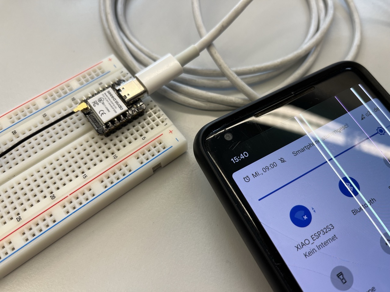
The ESP32 creates a WiFi network to which a phone or other device will be connected to interact via a website with the ESP.
IP adress: 192.168.4.1
Demonstration of the ESP32 web server setup. The website which can be accessed when connected to the ESP WiFi allows to control the LED on the XIAO board.
© 2026 Richard Draxler – Creative Commons Attribution Non Commercial
Source code hosted at gitlab.fabcloud.org