5. 3D Scanning and Printing
Ideas
- Luedo housing
- housing with slots for magnets, later installation with glue and cover sticker
- version with sticker from the bottom to seal magnets in place
- version with sticker from the inside of the housing to seal magnets in place
- embed magnets into Luedo housing
- version with two layer seal at the bottom
- housing with slots for magnets, later installation with glue and cover sticker
- Luedo reflector
- thinner reflector, hollow design
Checklists
Checklist: personal
- DeepL check spelling, grammar
- GPTcheck for better markdown
- Test external Links
- repair file links, replace .png -> .jpg; .mov -> .mp4
- remove dates
- improve safety section
- improve enviromental section
- add files for SLA 3D models
Checklist: Nueval:
- Linked to the group assignment page
- Explained what you learned from testing the 3D printers
- Documented how you designed and 3D printed your object and explained why it could not be easily made subtractively
- Documented how you scanned an object
- Included your original design files for 3D printing
- Included your hero shots
3D Printing
FFF/FDM 3D Printing
Dimensional Accuracy Test 
Group Assignment
20.02.25
Link to Group Assignment - 05. 3D Scanning and Printing
This is the test file we printed: Print test (Thingiverse)
For this week's group assignment, Benedikt already printed a common printer test on our Prusa MK4 and Prusa XL printers in two different materials, PETG and PLA.
Jakob and Richard (that's me) then decided to select a few dimensions of the test object.
The measured dimensions are shown in the picture below.
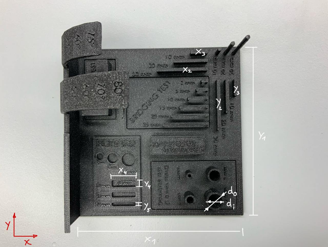
We used digital calipers to take the measurements.
The measurements we took are not scientific in any way, but they are accurate enough to give us a good estimate of our dimensional accuracy.
I've created a small deviation table to be able to estimate the deviations from the original.
These are the results we got.
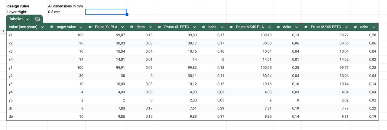
If you compare the deviation between the two printers, there aren't that many differences.
They are very close in the reproduction of 3D geometries.
The main difference could be seen between PLA and PETG, PETG produces less accurate prints and a more inconsistent surface than PLA, at least with the original Prusa filaments and their factory provided presets.
No matter what material or printer you choose for round diameters, it is recommended that you add approximately 0.15 or 0.2 mm to all diameters for accurate reproduction.
Sand Infill [Failure]
25.02.2025
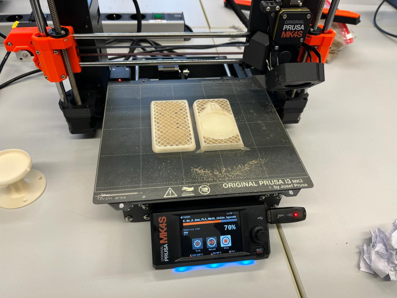
I decided to print the files I created in 02. Week (CAD Week) to see if my idea to improve the mounting system actually works or not.
Let's print some parts quickly - or so I thought.
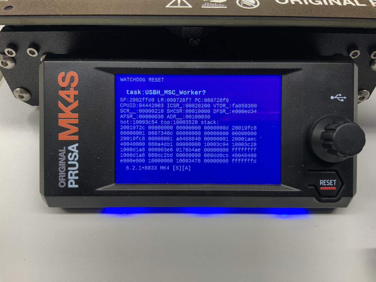
I got a corrupted USB stick that crashed the Prusa MK4s printer with a "watchdog reset" error.
After some quick research, I found out that a corrupted USB stick could be the source of the problem.
After a quick reset with the reset button, everything was back to normal.
During this week's group assignment, I found that the shape reproduction and accuracy of PLA was superior to the precision of PETG, which I had previously used for most of my other prints.
For the improved mount, I used the following print settings:
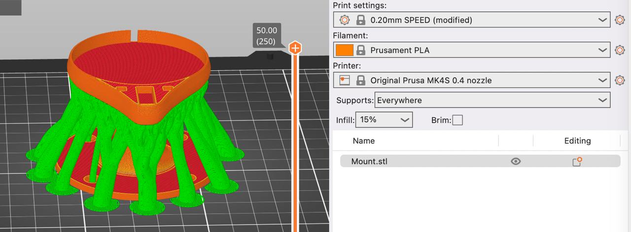
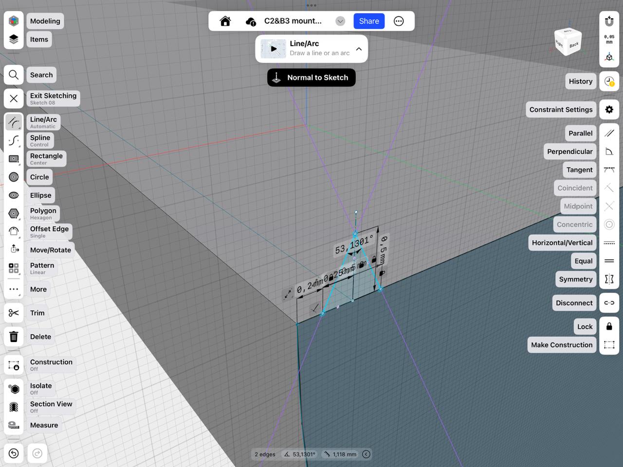
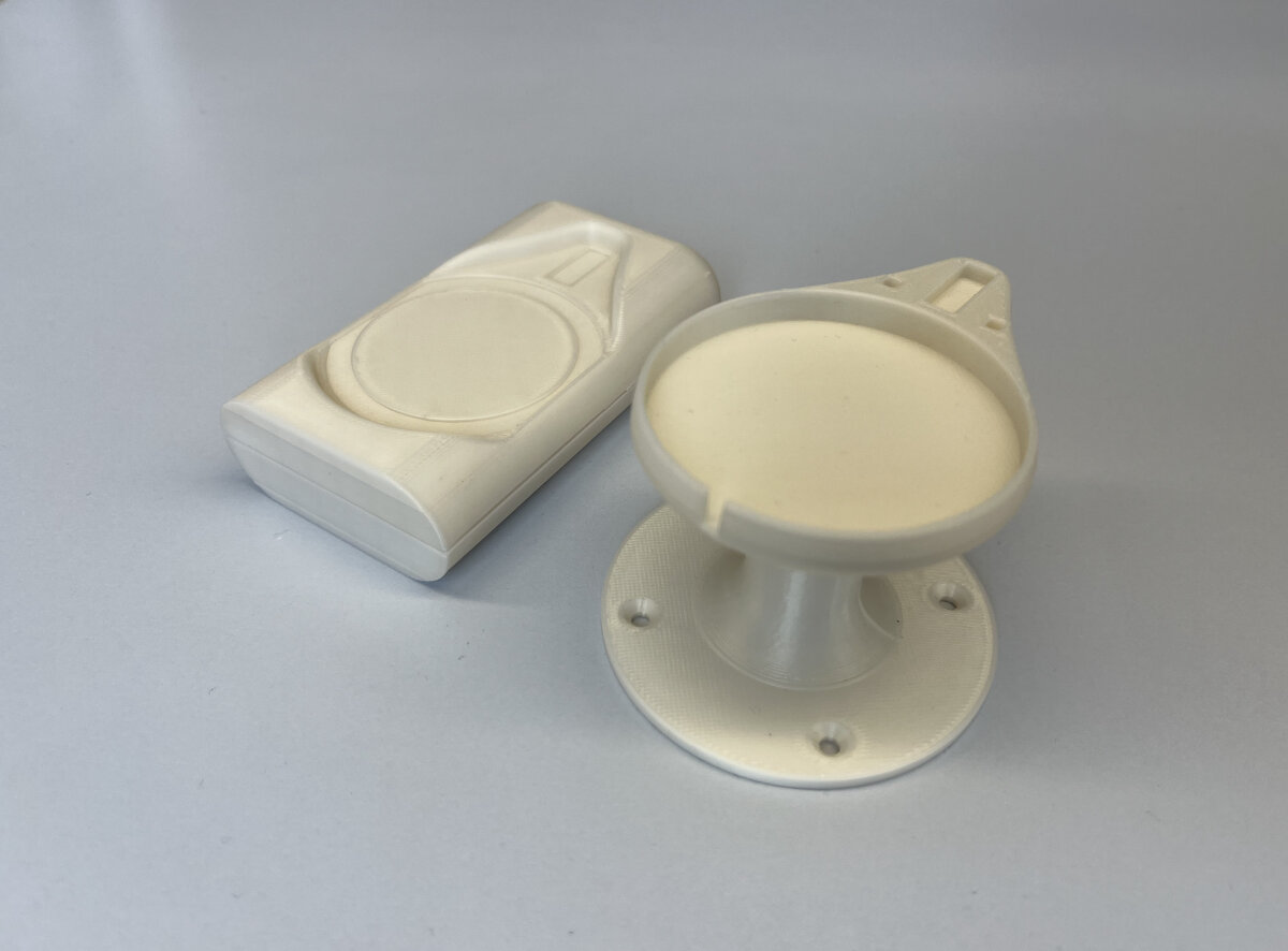
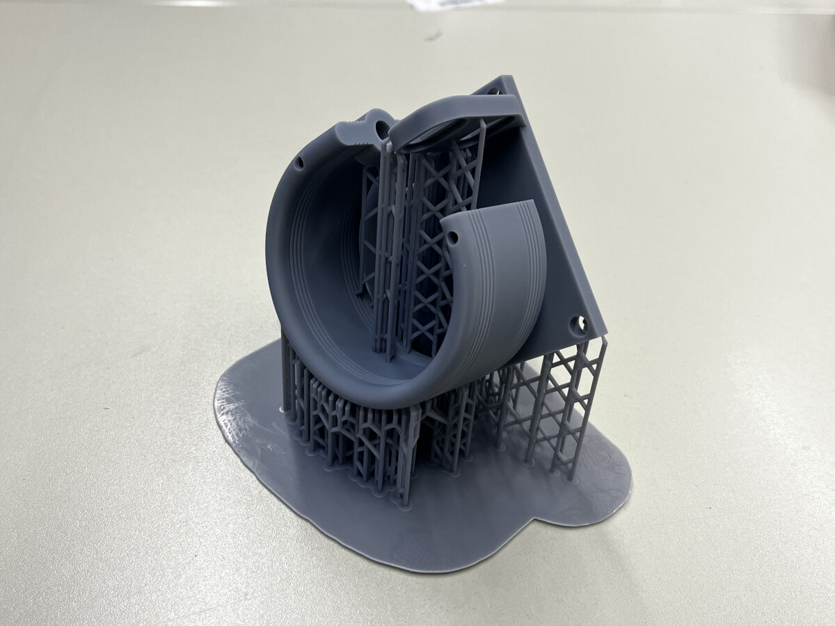
For the Luedo lamp itself, I split the body in two halves to
- reduce material loss in the support structure
- improve the surface quality (without support contact points)
- add sand to the filling structure
After splitting the body in two, I created an alignment lip using the sweep feature of Shapr3D (my favorite 3D modeling software).
26.02.2025
To create a part that could not be produced subtractive, I decided to stop my print halfway and fill some of it with sand.
Why do this? When a mockup is used to determine haptic usability aspects of a final prototype, it is useful to have an accurate weight representation of the part.
For this week's assignment, I will just do a test run of the process to see if it works for me or not.
- Spoiler: it was a big failure. But more on that later.
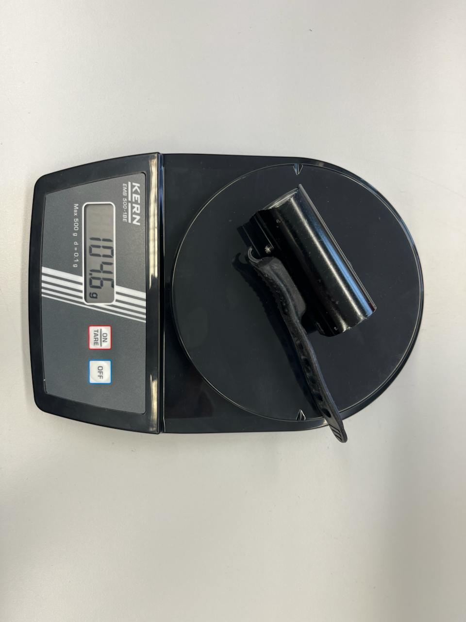
I started by using a scale to determine the amount of sand I needed and measured the exact amount needed (100g total weight).
(My reference for this was an existing bike light.)
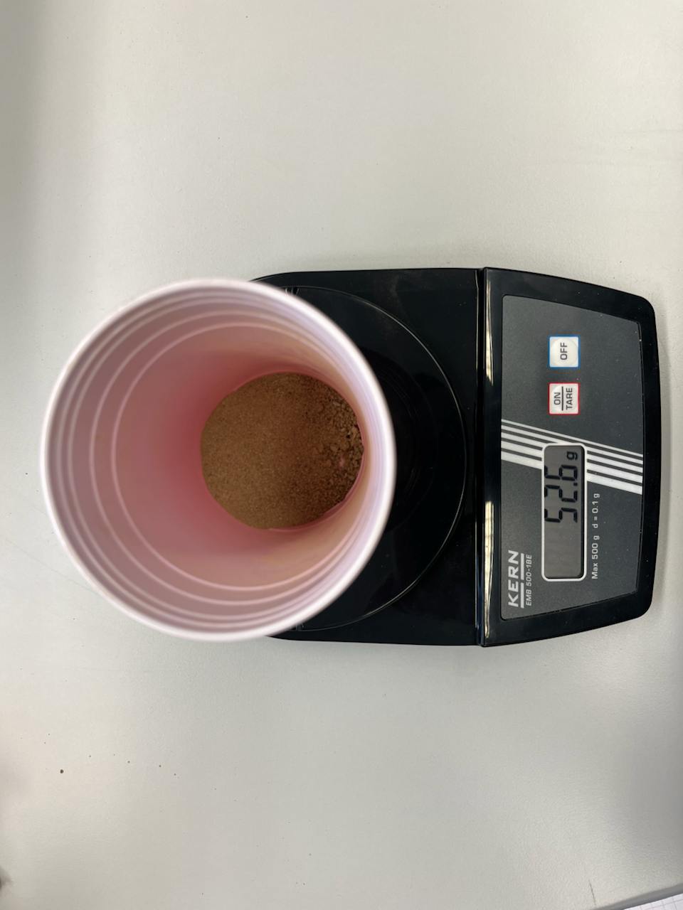
Once everything was weighed correctly, I found that filling the infill was a slow and incredibly tedious process.
I then made sure that none of the sand touched the top layer to avoid contact with the printer's nozzle.
I imagined that the printer's acceleration and fan airflow might be a problem, so I decided to slow down the printing and rotate the fan.
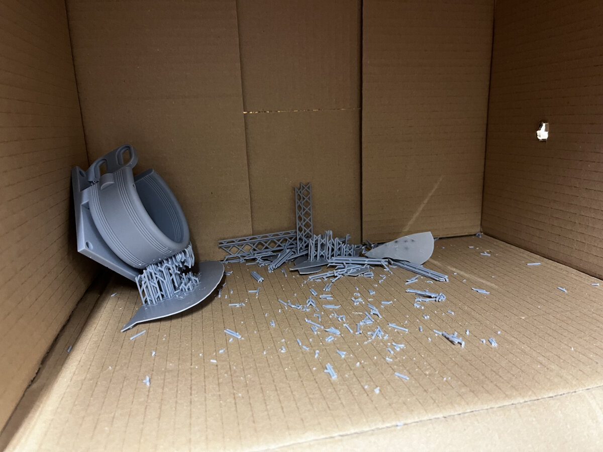
And this was the result:
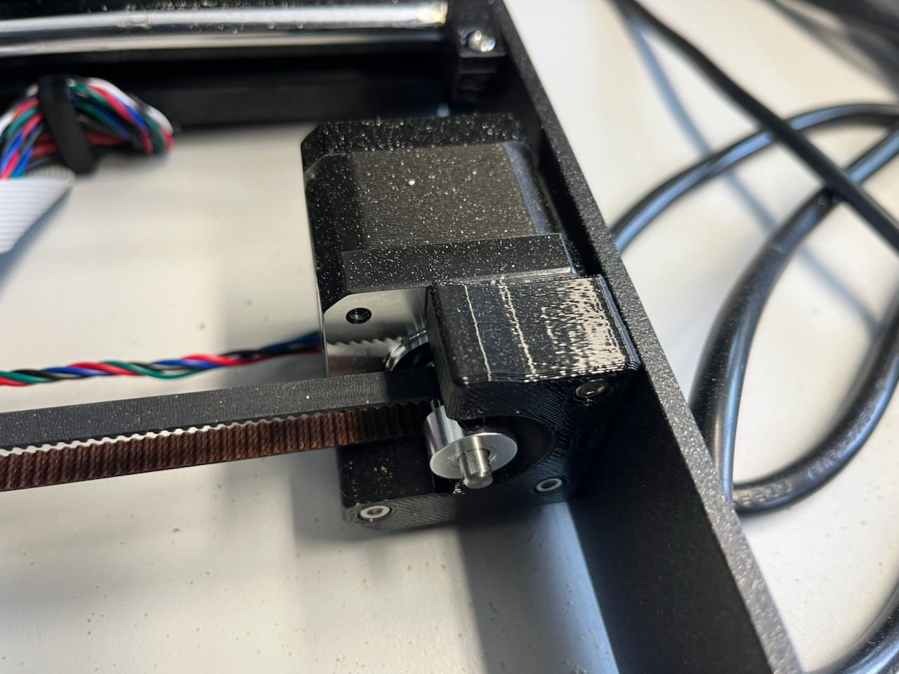
Loose sand near precision machinery is just not a good idea.
Due to the harsh acceleration changes of the printer, all the sand was spread all over the printer, and when I say all over the printer, I mean all over the printer.
The particles got into the linear rods and stepper motors.
(The printer is still working, I removed everything in a tedious cleaning process).
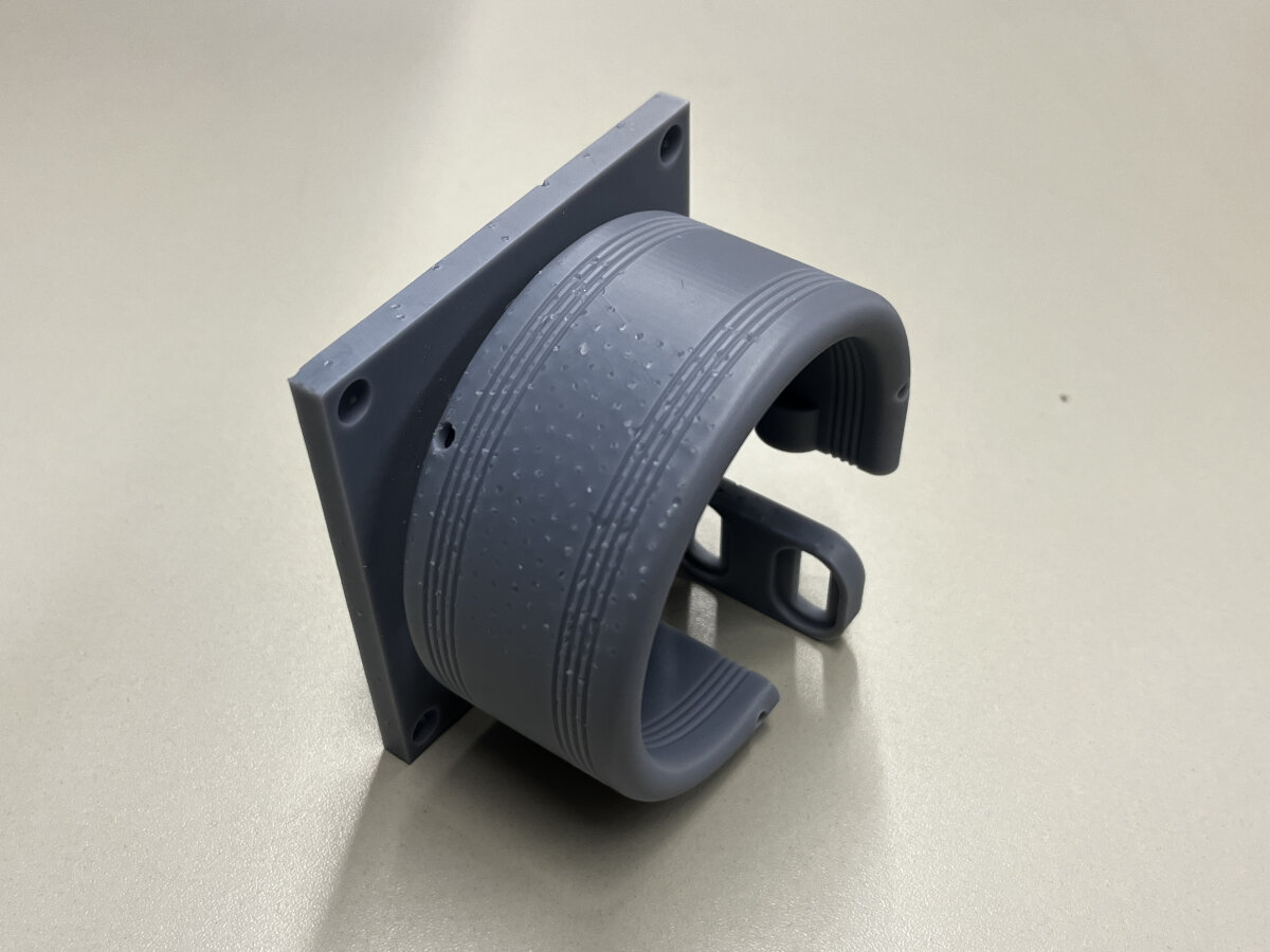
After removing all the visible sand with a vacuum, I successfully completed the print (with a small rock in the infill - so that part couldn't be subtracted).
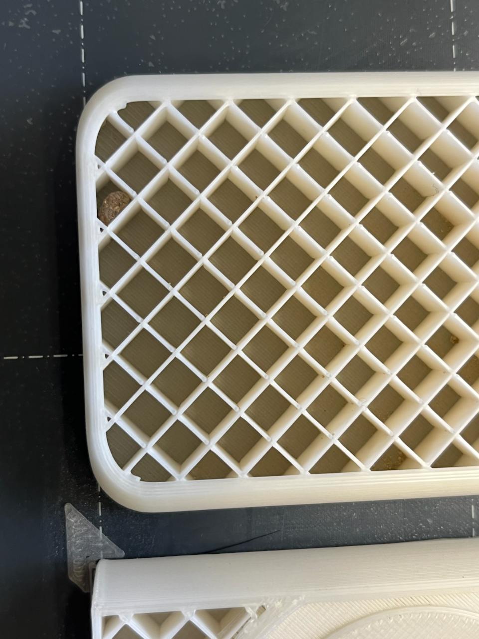
The finished print
Files
Here are the .stl files for the Mount.stl and Mockup.stl
Tolerance and Fitment Tests
(Addition from Machine Building - Week 12)
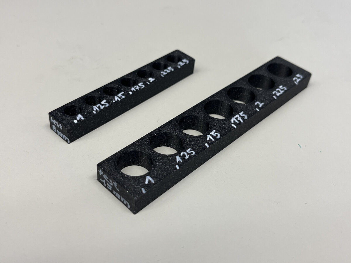
During our machine assignment we had many issues with the fitment of our 3D printed parts, why we printed a 8 mm and 15 mm friction fit test.
I modeled a test piece in Inventor with increments of 0,125mm to find the right friction fit.
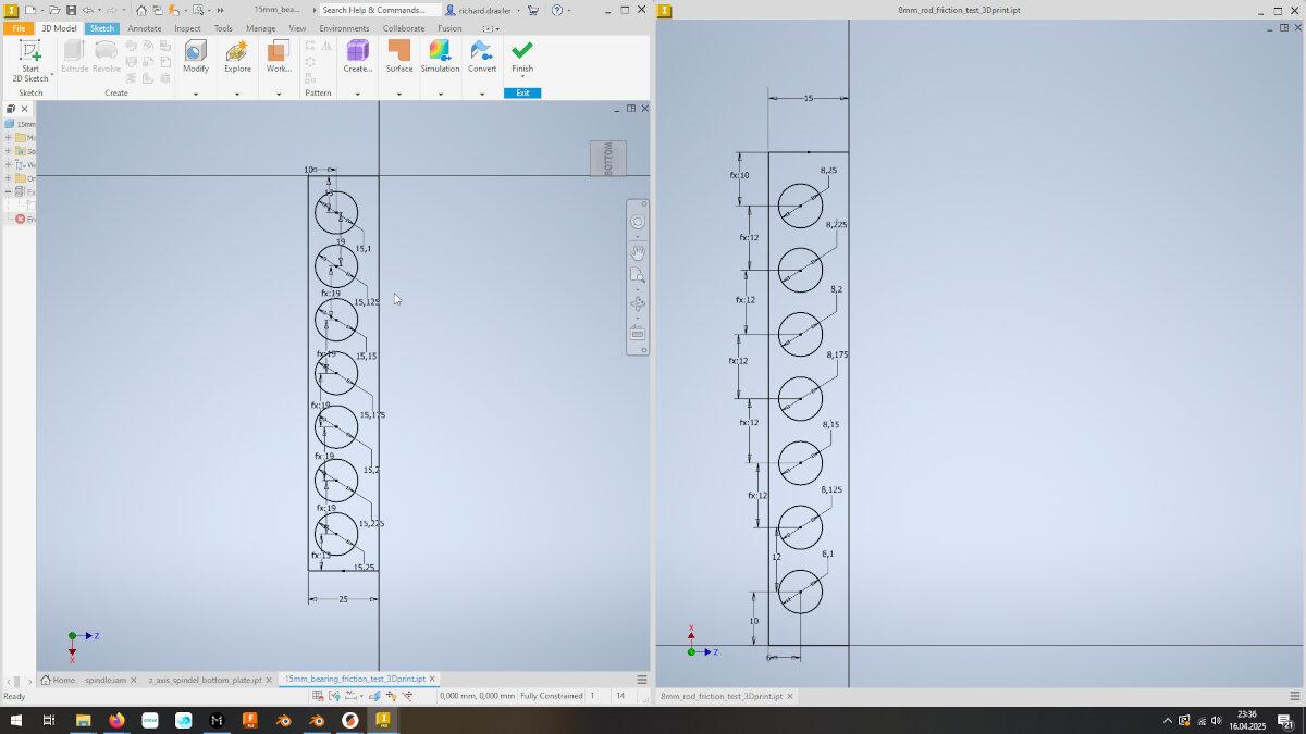
I exported the files as .stl and sliced them with Prusa Slicer
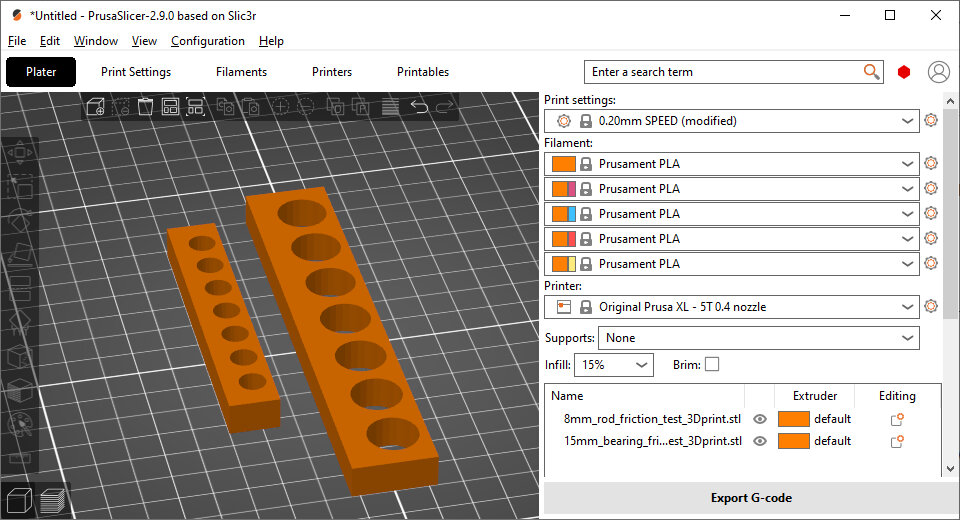
These are the print settings I used for the friction fit test:
- Prusa XL
- Prusament PLA Galaxy Black
- 0,2mm Speed
- 15% infill
8 mm Test
| Modeled diameter | 8,1 | 8,125 | 8,15 | 8,175 | 8,2 | 8,225 | 8,25 |
|---|---|---|---|---|---|---|---|
| Actual diameter x | 7,94 | 7,94 | 7,95 | 7,93 | 8,06 | 8,02 | 8,08 |
| Actual diameter y | 7,93 | 7,9 | 7,95 | 7,98 | 8,05 | 8,05 | 8,05 |
| Deviation | 0,165 | 0,205 | 0,2 | 0,22 | 0,145 | 0,19 | 0,185 |
Total average deviation: 0,187 mm
15mm Test
| Modeled diameter | 15,1 | 15,125 | 15,15 | 15,175 | 15,2 | 15,225 | 15,25 |
|---|---|---|---|---|---|---|---|
| Actual diameter x | 14,92 | 14,99 | 15,03 | 14,99 | 14,95 | 15,02 | 15,02 |
| Actual diameter y | 14,92 | 14,93 | 14,95 | 14,93 | 14,93 | 14,97 | 14,98 |
| Deviation | 0,18 | 0,165 | 0,16 | 0,215 | 0,26 | 0,23 | 0,25 |
Total average deviation: 0,209 mm
The deviation test showed, that small changes (0,125) in the diameter can not be reproduced with Prusa FFF printers. The before mentioned recommendation to add 0,15 to 0,2 mm to every diameter confirmed once again.
Results
Files
SLA - Resin 3D Printing
Shopping List Resin Printing Items
- Metal tray for resin vats to clean them later
- microfiber cloth for cleaning the display
- Lab coat with long selves
- easy operable isopropyl dispenser
- easy operable isopropyl paper towel dispenser
- paper towels that do not disintegrate
- vat drip holder, funnel holder
- microscale, to estimate remaining resin in a bottle
This is an addition from the Week 16 - Wildcard week
I am completely new to the resin based printing process, that's why I documented everything in detail. SLA printing is rarely used in our lab due to the additional steps and the mess. Therefore, a good documentation is a useful to refresh my memory later when I have to go back resin printing in the future.
Videos I watched:
- Ph.D. Chemist Explains 3D Printer Resin - Youtube
- Resin 3D printing beginners step by step guide - Youtube
Helpful resources:
The Hardware: Print Setup
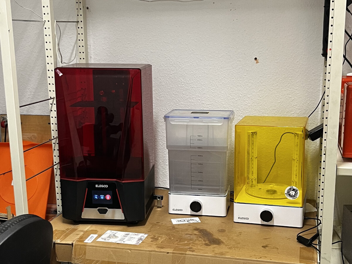
Current print setup. There is a lot of room for improvement!
- Printer: Saturn 2
- Wash and Cure station: Mercury XS Bundle
Safety
Personal Protection
Equipment: Personal Protection Equipment (PPE)
In our FabLab we use the following items for personal protection:
- Half Mask Respirator
- Filters against particles and organics vapors
- Nitril Gloves
- Safety Glasses
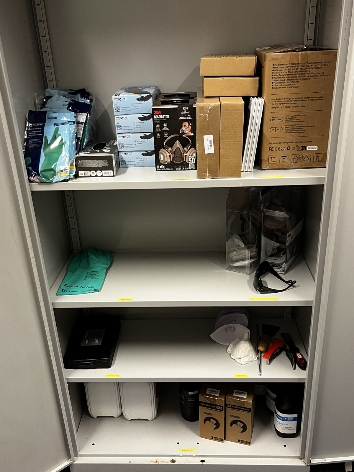
From top to bottom:
PPE and replacement parts, additional masks and UV glasses, tools, resins and isopropyl. All SLA printing related equipment is stored in a chemical cabinet.
Usage: Personal Protection Equipment (PPE)
Correct usage is critical
Personal Protection Equipment does not protect you if it is used in the wrong way!
Gloves
Always wear nitrile gloves while handling uncured resin. Nitrile gloves with a thickness of 0.15 should be switched every 5 minutes when being directly in contact with resin or contaminated isopropyl alcohol. Chemicals slowly penetrate the glove overtime.
VOC Mask
Always wear a respirator mask when handling resin. Resin emits VOC's (volatile organic chemicals)
Protective Glasses or Face Shield
Always wear an eye protection either in the form of safety glasses or a complete face shield.
Clothing: long sleeves, long pants, closed shoes
Always cover your skin completely
Environmental safety
Uncured resin is dangerous for living organisms of any kind. Uncured resin should always be cured before disposal. Wet tools or cleaning cloths should be cured extensively before being disposed of in the household trash.
Materials
Resin
Resin Types:
- draft resins
- High-resolution resins
- High temperature resins
Resins in our Lab
| Name/Link | Tested? | Approved? | Notes |
|---|---|---|---|
| ABS-like Resin V3.0 Ceramic Grey | good results | ||
| Water-washable Resin V2.0 Ceramic Grey | brittle, sticky residues on final parts | ||
| 3D printing, synthetic resin, Ultracur3D ST 45 transparent, 1 kg | - |
Cleaning/Washing
We use 95% or 99% Isopropyl alcohol for optimal cleaning results.
Waste (Isopropyl, Water, Tissues, Containers)
Reduce waste production
To reduce the overall waste production, let the finished resin prints drip-dry for a while (30 min+) to reduce the contamination of the cleaning solution.
Process
Slicing and Slicer Tools
For all Slicers: Settings and Notes
Layer Height:
| Layer Height | Application |
|---|---|
| 100 µm | draft prints |
| 50 µm | standard prints |
| 20-25 µm | very fine details |
| below 20 µm | needs to be tested, but it has probably no impact on visual print quality |
Layer Exposure Time
Curing time is significantly impacted by temperature. Optimal temperature is 25 °C. Deviating from this temperature can lead to adhesion issues/uncured layers
Bottom Layer Exposure Time
Bottom Layer exp. = 10 * Layer exp.
It is needed to cure the first layers longer, to ensure proper build plate adhesion.
Notes for the slicing process
- place components in the corner
- less flex of the construction foil
- resin can drip of sloped surfaces
- auto orienting the part is usually the best, accept functional areas exist
- usually place components 45° and 45° rotated (a cube would 'rest' on one of the corners)
- place components for every print in other places
- foil needs regular replacement
- one to two foils per liter resin
- foil wears based on exposure cycles
- 'Draft' known from normal FDM printing is called 'Pad' (SLA)
- reduce 'Pad wall slope' to 90° to avoid connection angle
- about 60% more surface area than projected footprint
- use hollowing for massive prints
- standard preset for layer height: 0,05 mm
- first layers for the pad will be cured longer
- 5 to 10 times longer cure time for the pad
- initial layer height ensures intense cured support foot
- often it is useful to add more support
Elegoo SateLite 3D [Failure]
Since we have an Elegoo Saturn 2 SLA printer in our lab stuck to the default slicer option provided by the manufacturer. I downloaded and installed the slicer from the official website.
After the installation process I did the quick tutorial to later add our labs materials:
Water-washable Resin V2.0 Ceramic Grey
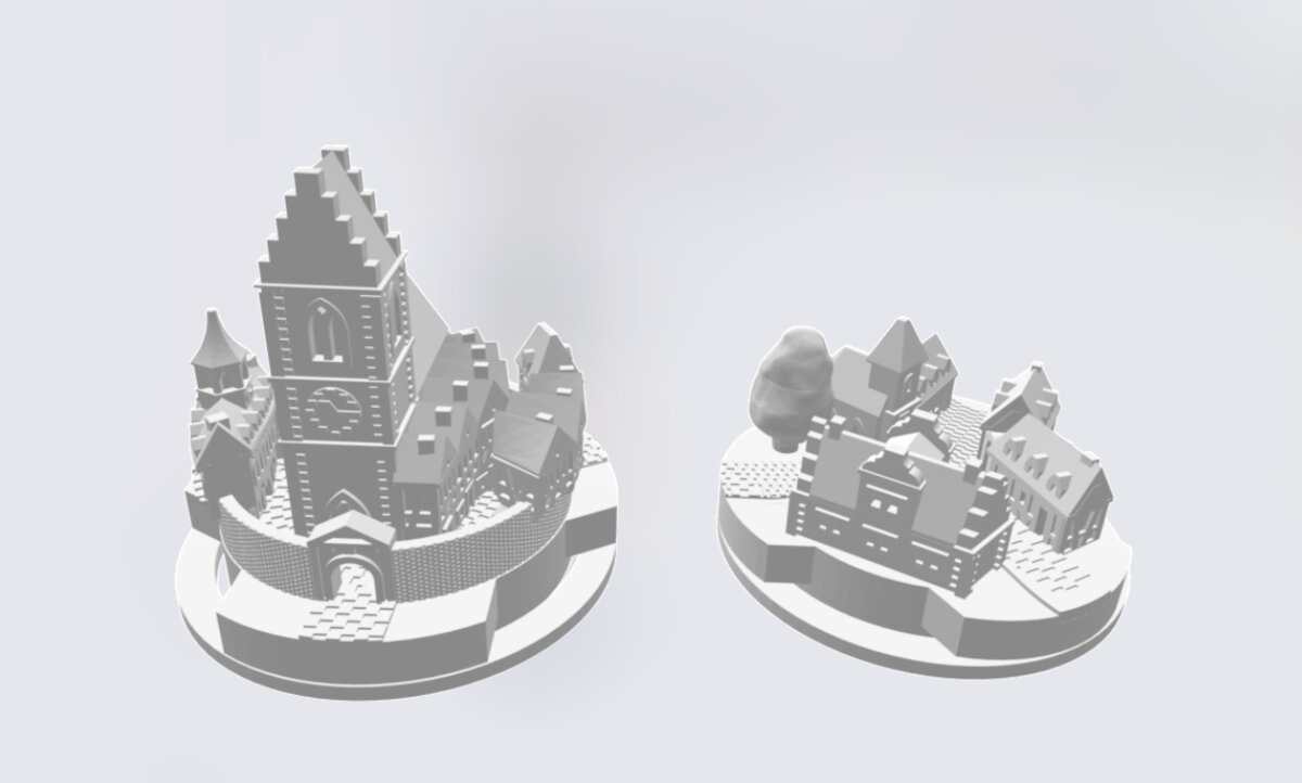
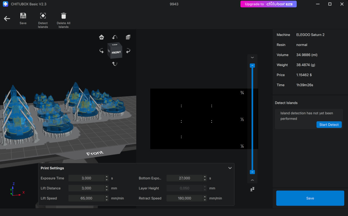
I imported the relevant presets into the SateLite slicer and kept all settings default. As a first test project I chose a couple of figures/houses for the board game "settlers of catan".
For the support I choose the automatic option and placed the objects parallel (with 15 mm distance) to the inverted bed.
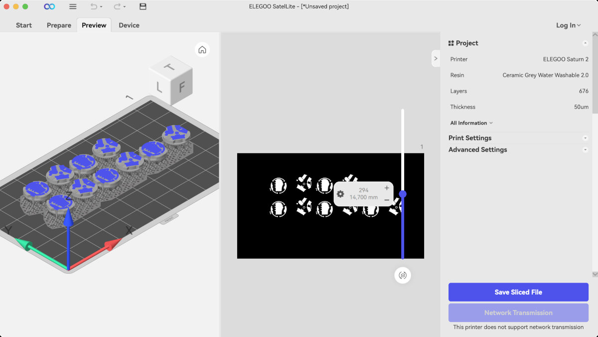
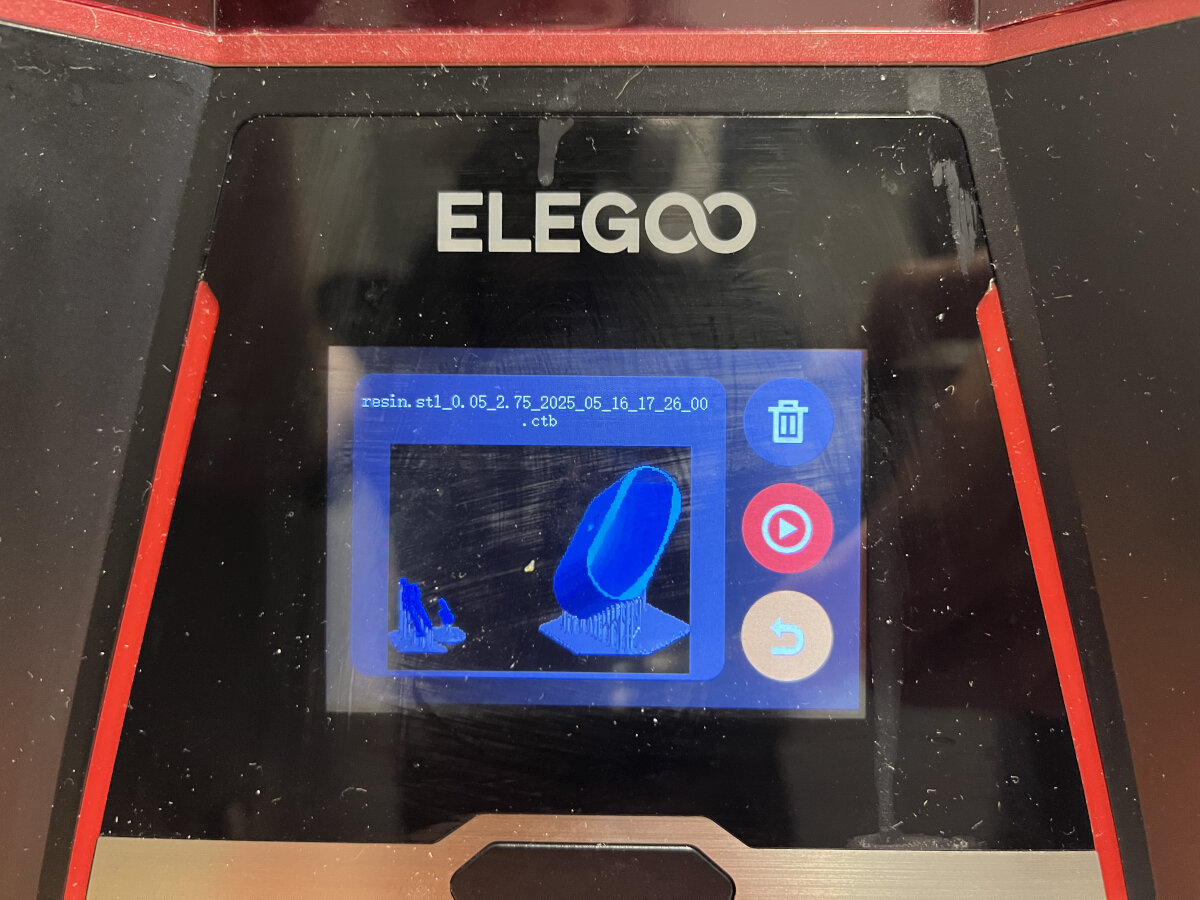
In the preview after slicing there is the monochromatic picture displayed which is sent to the printer. This will be extremely useful for troubleshooting later. I exported the print file in the .goo file format and copied it to the USB drive. After inserting the USB Stick and trying to print the Saturn 2 SLA printer wouldn't recognize the file. The machine gave me the error Unknown File Format
On the stick were files which were previous files which were all in the .ctb format.
Therefore, I used the UV tools plugin to convert the .goo as a .ctb out of SateLite.
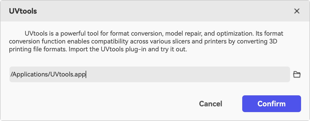
I tried different versions of the .ctb file type in the export window: V1,V2,V3,V5 none of them worked. I always got the error: Unknown File Format
Note: Maybe we should update the firmware of our Saturn 2 to achieve SateLite compatibility
Chitubox Basic
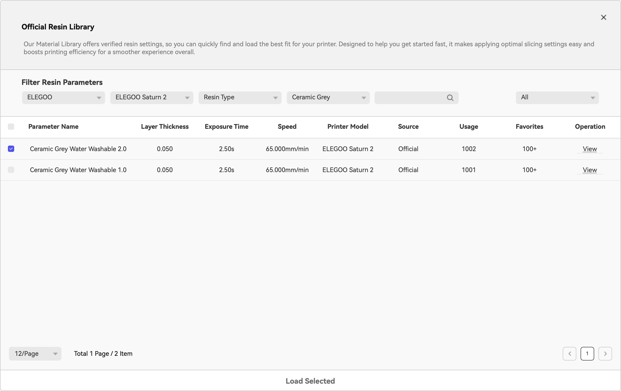
Then I switched to Chitubox Basic and set manually the parameters form Elegoos Material library.
I got the important parameters for the resin form the official Elegoo Material Library.
After exporting the as .ctb and trying to print the file, everything worked as expected.
Prusa Slicer
Import profile for Saturn
File -> Import Config to import the preset.

Debugging the sliced file - Island detection
Islands are free floating particles, that are not connected to the already cured part. Islands cause print defects.
ChituBox has a built-in Island detection tool. For more advanced options UV tools is a great choice.
Avoid free floating "Islands" and repair them with UV Tools
UV Tools tutorial
Printing
Preparation of the Printer
Remove the vat lid!
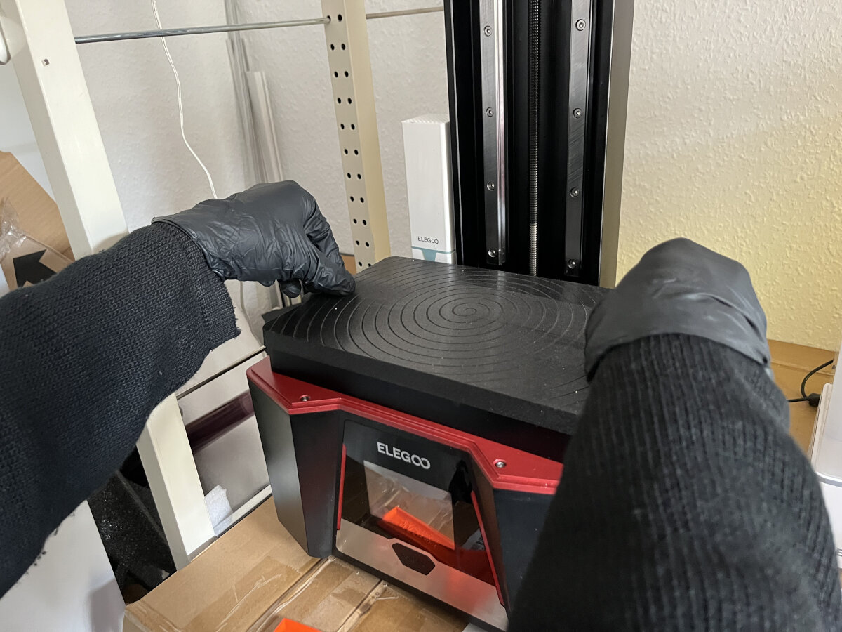
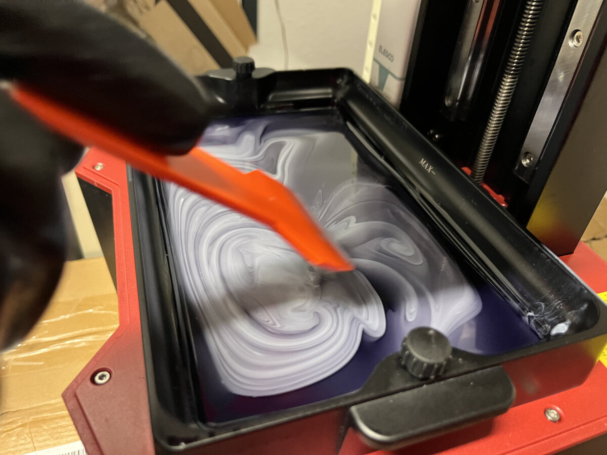
Shaking or mixing the resin before printing very important. After some time the photoactive and filler component of the resin separate. While filling the tank with resin, keep an eye on the resin level. It should not exceed the max level since the build platform takes up volume while submerging in the liquid.
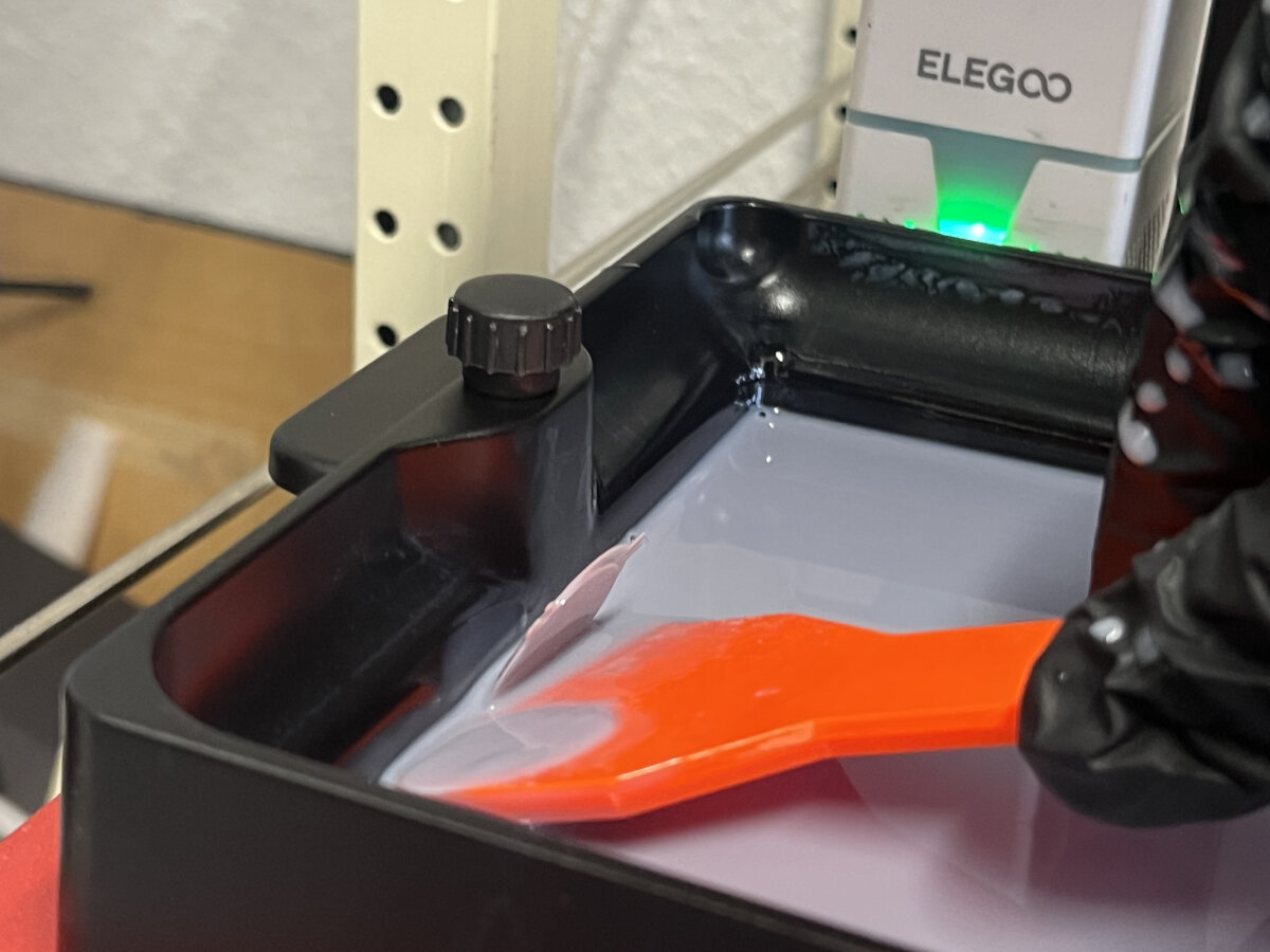
Cleaning the Resin Tank
Warning
- don't scratch the PFA film while trying to remove old prints
- clean the metal part with isopropyl alcohol
If previous prints contained loose islands and/or other particles these will accumulate in the resin tank. Sometimes failed prints either stick to the vat or cure and float around in the resin tank.
Loose, but cured parts from previous prints
Some cured pieces only appear after draining the tank
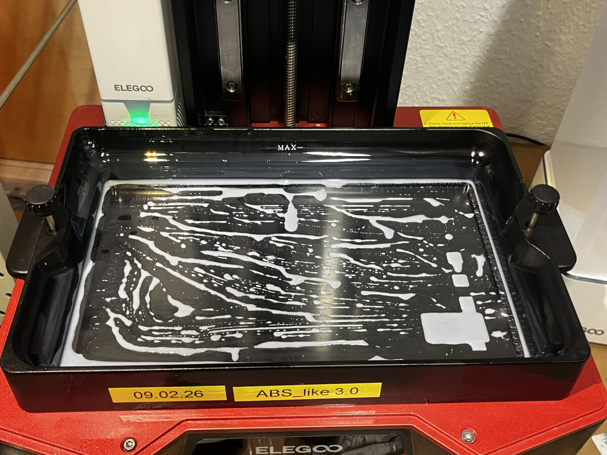
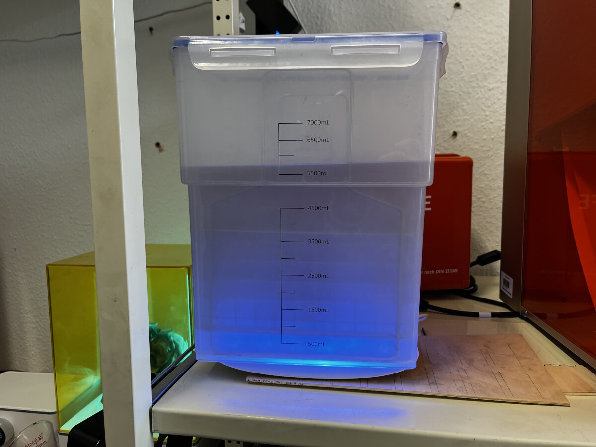
During the next print these particles will cause issues for sure. Therefore, clean the tank by fully curing one complete layer. This will collect all free floating particles and cure them to a solid base.
All debris gets cured to one layer, which can be removed fully cured and disposed safely.
Cleaning the Build Plate
Use Isopropyl to clean the Build Plate before every new print and after every print to avoid accumulation of leftover resin.
Cleaning the LCD
this method is not yet tested
Clean the printer display with a piece of tape
Starting the Print
Printing from USB
Insert the USB thumb drive before powering on the printer, otherwise it will not be recognized.
Hopefully everything worked, if not jump to the issues section.
Issues
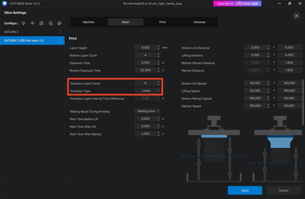
Missing transition Layers
Fix: Add approximately 8 transition layers after the bottom exposure layers to create a smother transition between the hardness of the cured layers.
Bottom Layer adhesion to low
 This can have multiple reasons, either the Bottom Layer Exposure time was too short or the built plate was not cleaned properly
Fix: Clean the build plate with isopropyl before printing.
Particles on the FEP Foil
In this example some small particles were stuck on the FEP foil due to insufficient cleaning before the print process.
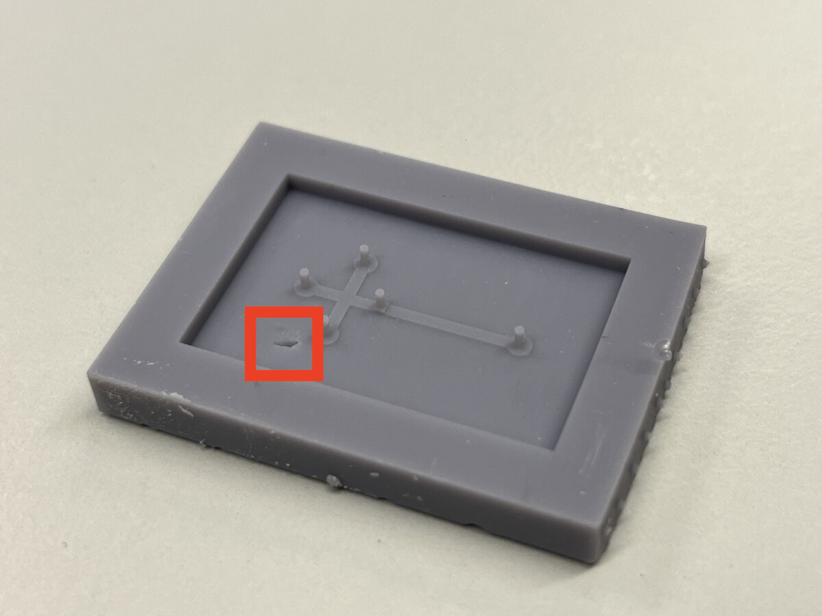
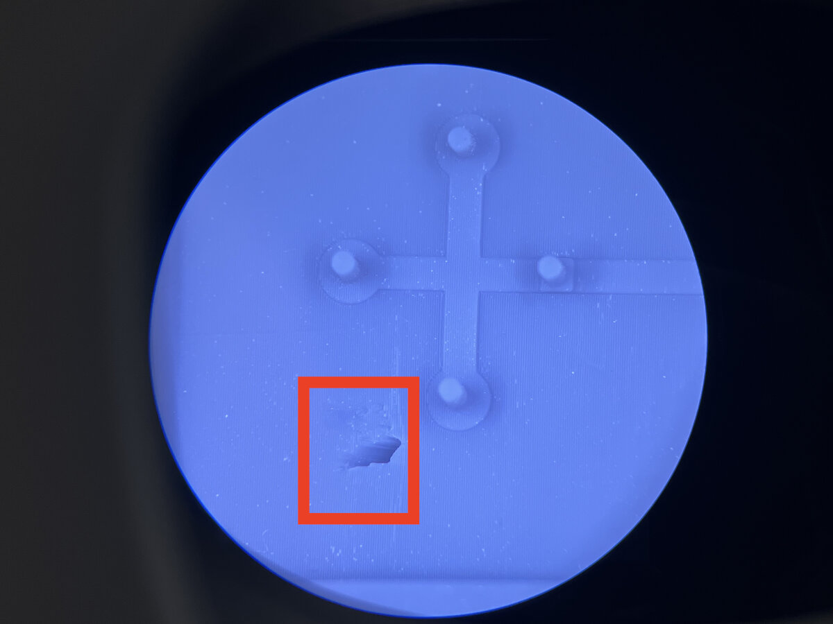
Fix: Cure the whole tank before printing. Section: Cleaning the Resin Tank
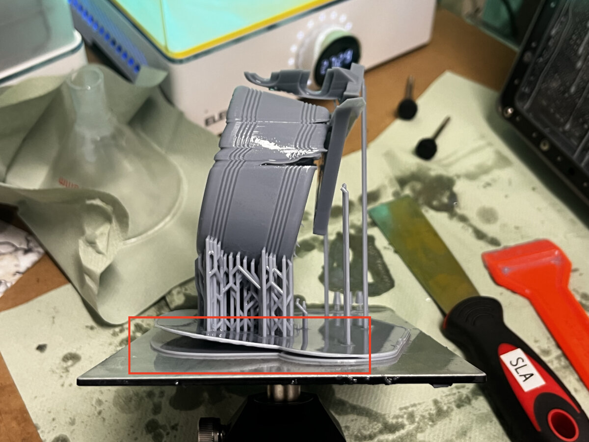
Suction cup effect
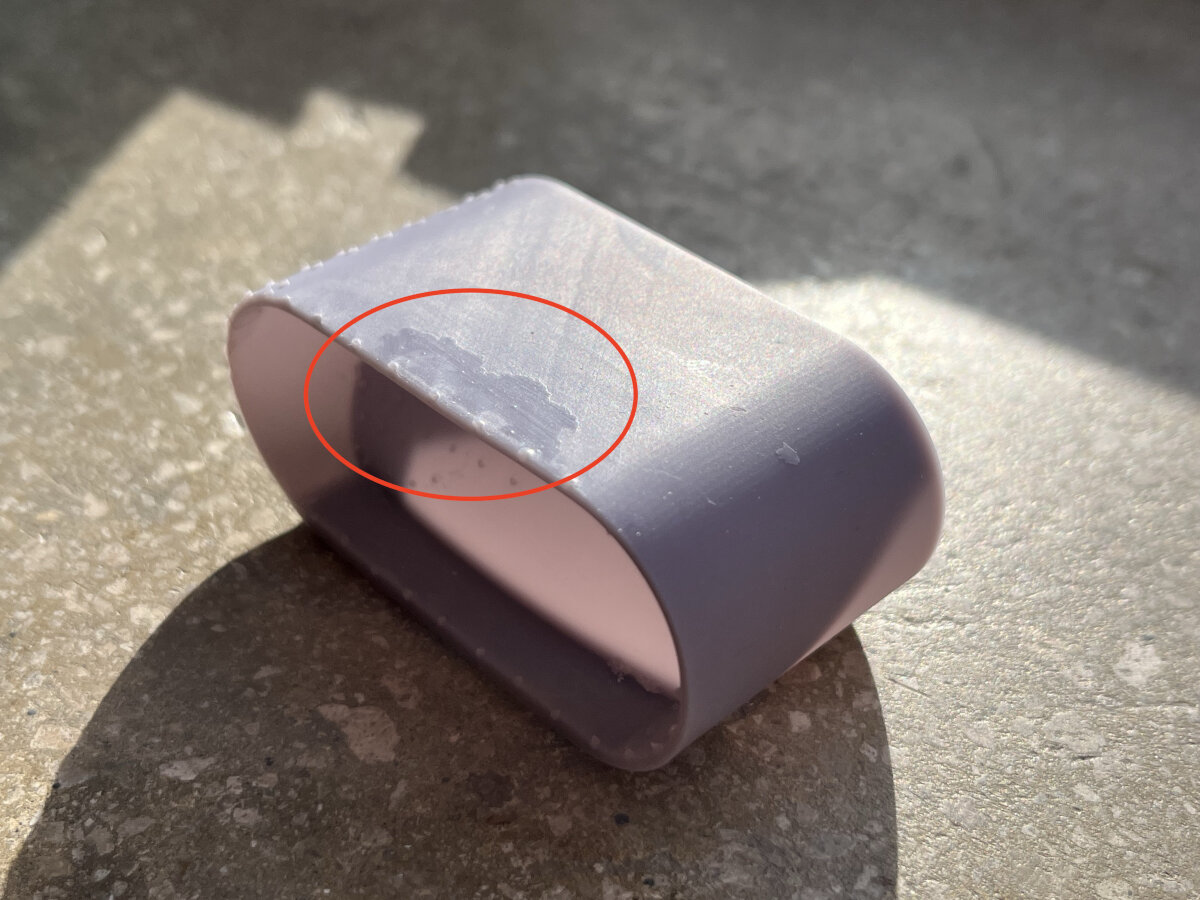
Unlike in traditional FFF printing hollow parts are difficult when fabricated as an SLA resin print. Hollow parts will create a suction cup effect between the FEP foil and the already cured part. This leads to uneven layer lines due to vibrations during the print. The suction cup effect can easily fail complete prints, when printing larger cavities.
Here is a small example how uneven layer lines can look like due to small suction forces.
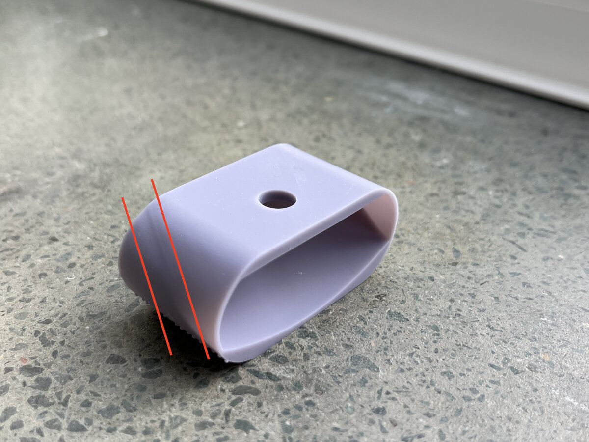
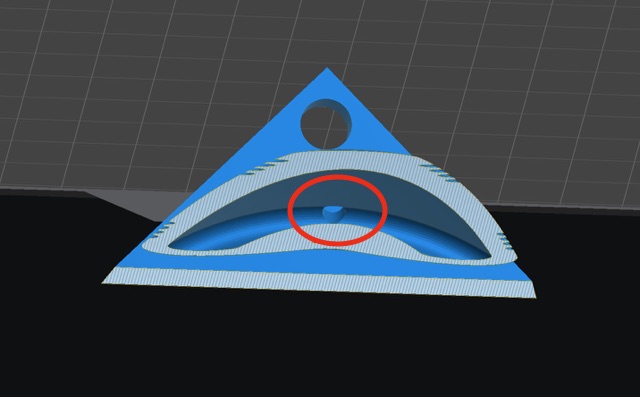
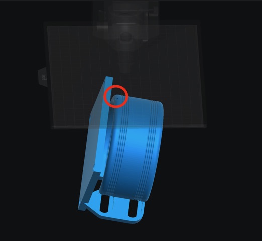
Fix: Place a ventilation hole at the top of the cavity to allow for sufficient airflow.
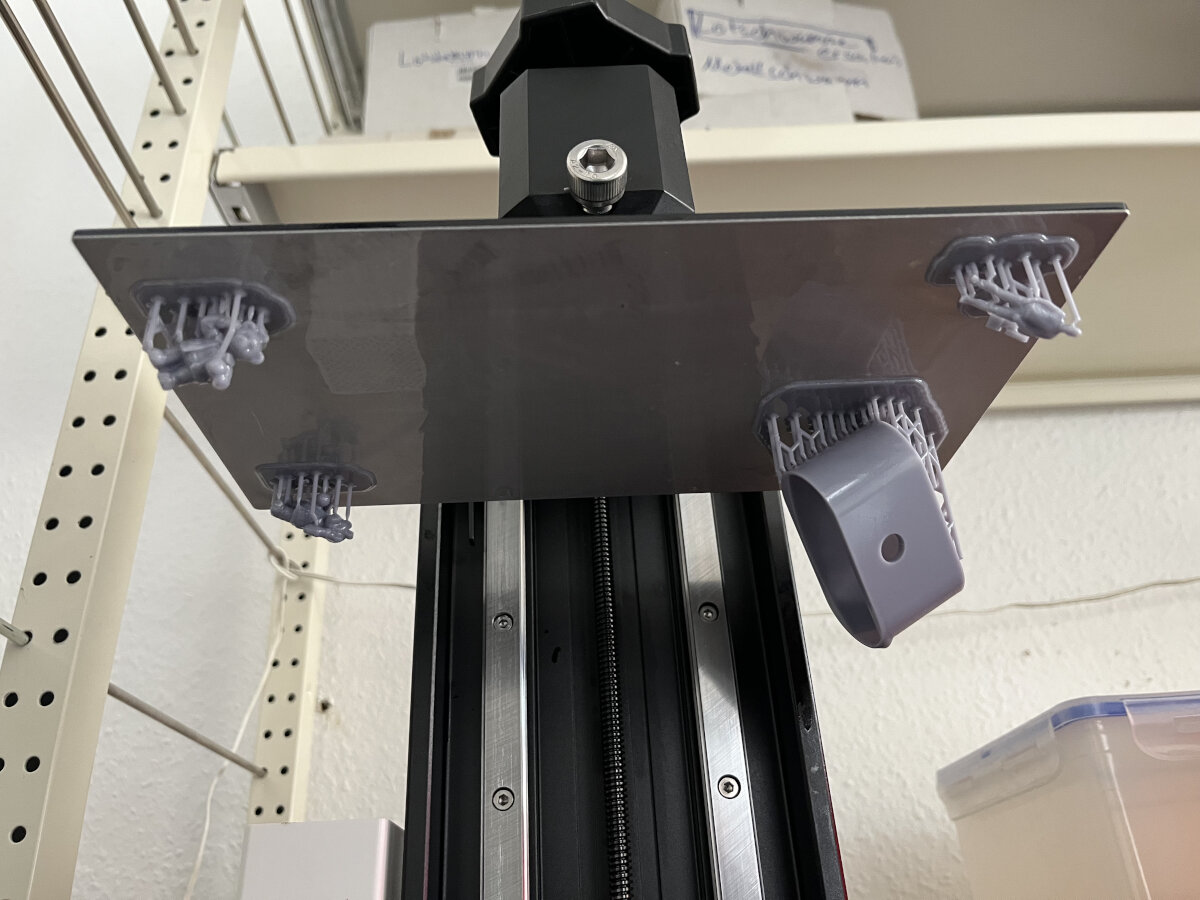
Parts parallel to the Build Plate
When placing parts paralell to the build plate uncured resin will accumulate on top of the already cured part. This will lead to a uneaven surface.
Fix: Place parts at a 45° angle on the build plate.
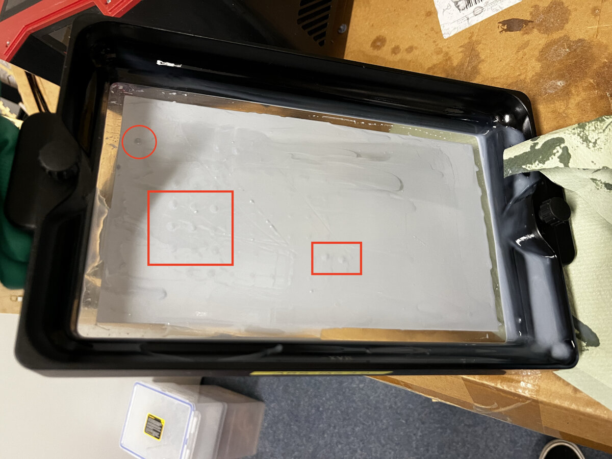
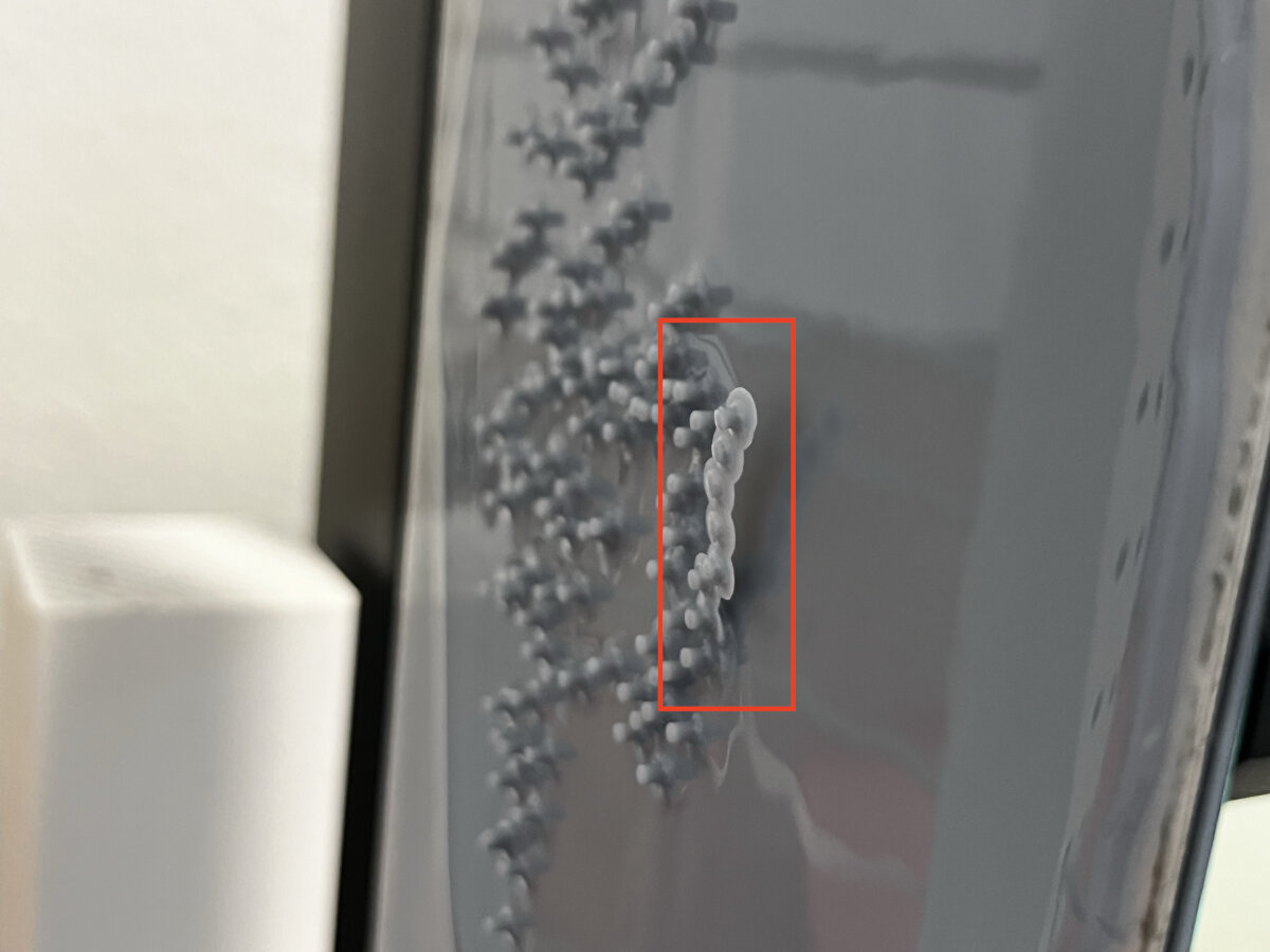
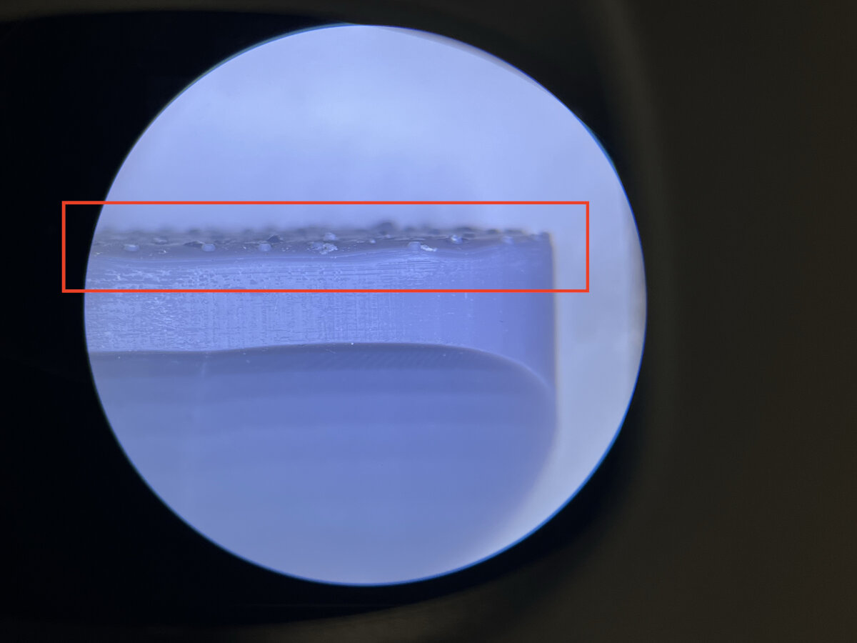
Residue from saturated washing fluid
After many washing cycles the washing fluid (in our case isopropyl) gets saturated and can not clean the parts anymore.
The result are droplets of cured or sticky resin on the final part. The stickiness remained even after many curing cycles.
Fix 1: Expose the washing fulid to some kind of UV light either from the sun or an artificial source. This will cure some resin. Let the fluid rest for a month and pour off the top two-thirds of the liquid to reuse it. The rest needs to be disposed safely.
Fix 2: Replace the cleaning fluid and dispose it safely.
Washing
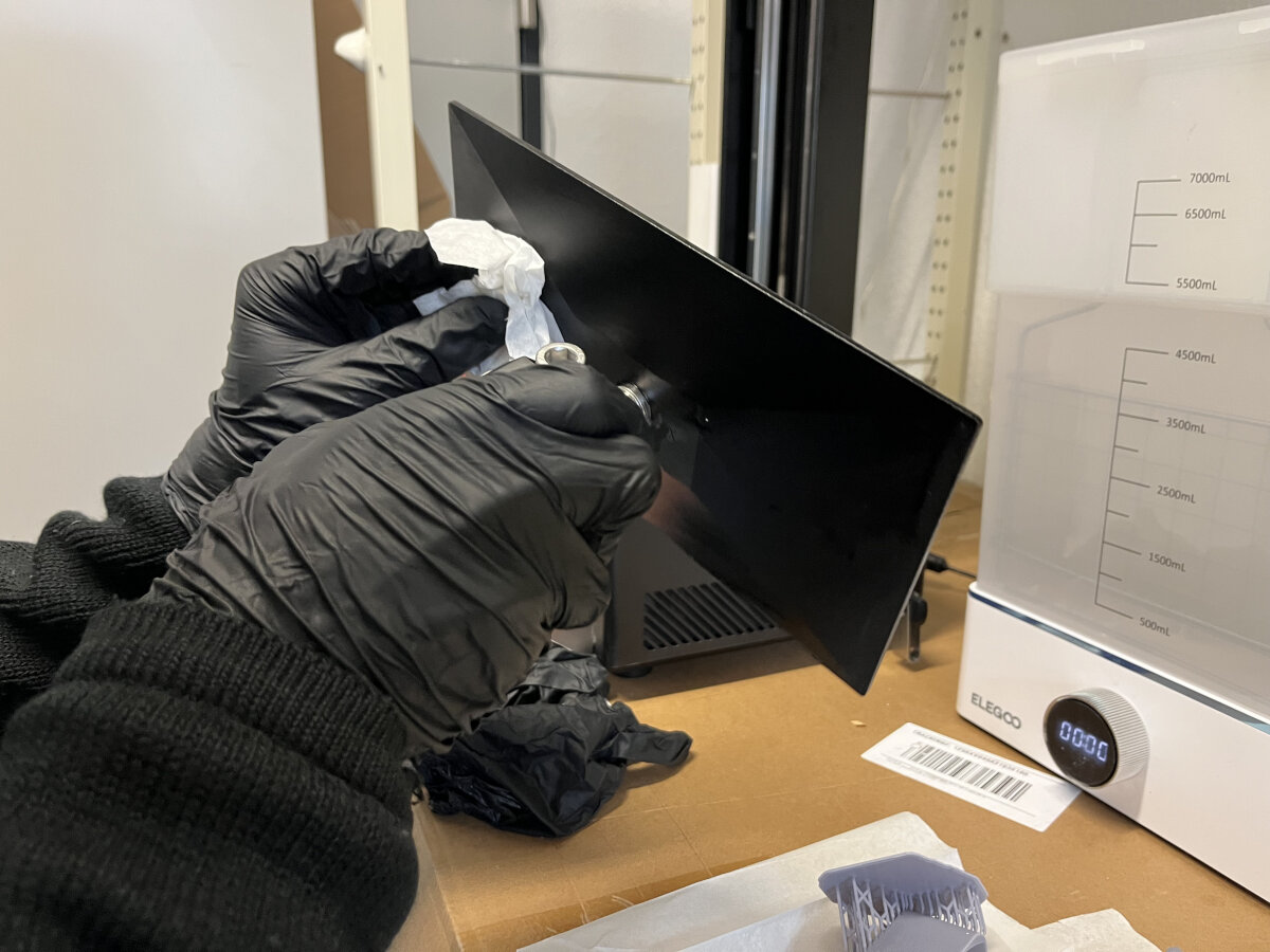
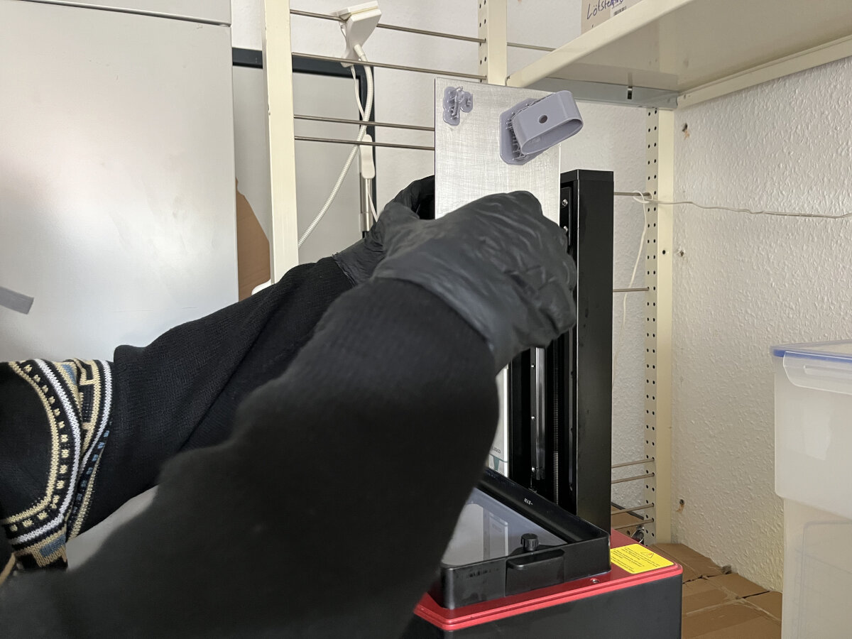
Remove the build plate from the printer while keeping it above the vat to avoid spreading resin.
Reduce waste production
To reduce the overall waste production, let the finished resin prints drip-dry for a while (30 min+) to reduce the contamination of the cleaning solution.
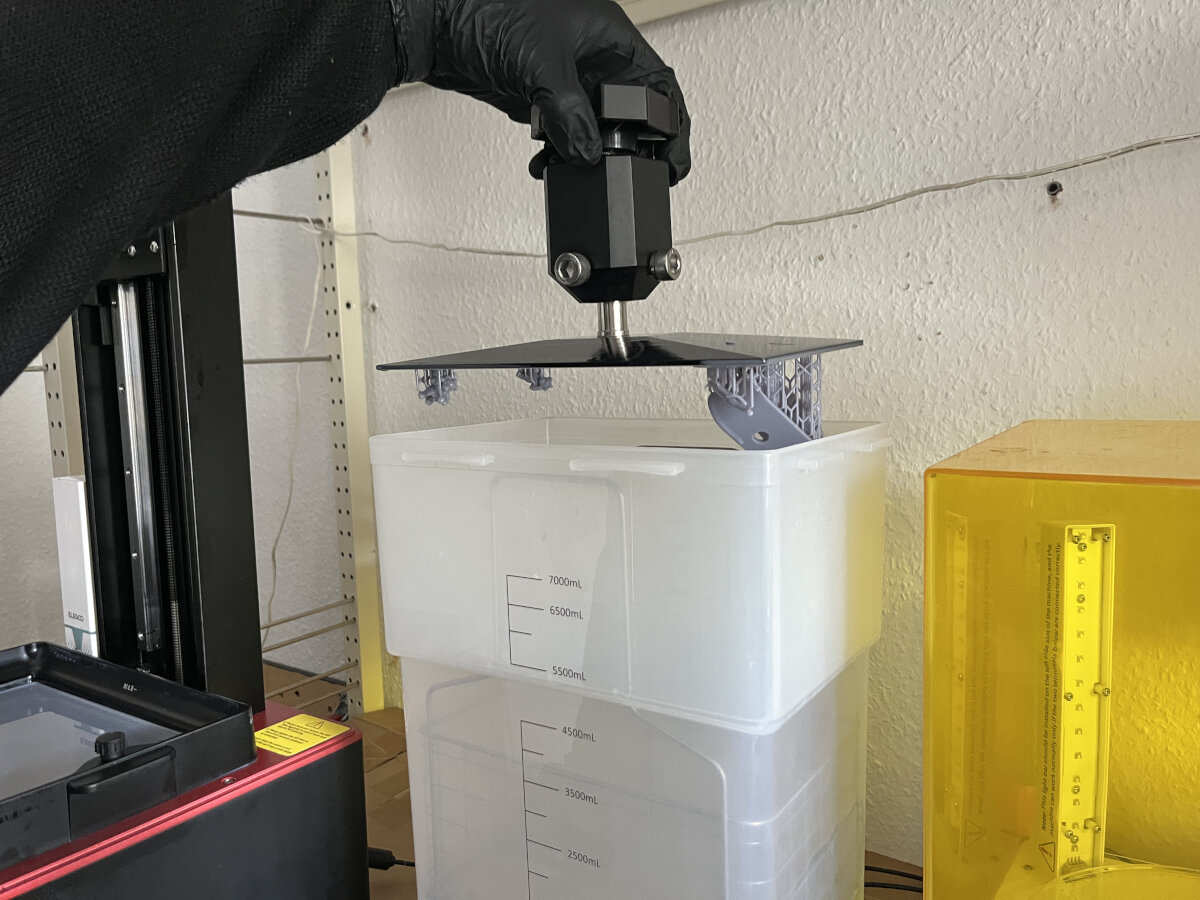
Submerge the whole build plate with isopropyl alcohol in the washing station. Turn on the magnetic stirrer for 30 min for larger prints or saturated alcohol.
When using fresh isopropyl the washing time can be reduced.
Avoid prints on the corner of the build plate
If objects are placed to close to the perimeter of the build plate the can interfere with the metal cage in the washing station. To avoid clearance issues place parts not in the outer 1 cm zone of the build plate.
Curing
After washing the parts, let them drain over the washing station. To remove the parts use a putty knife, while keeping the working area dry with paper towels.
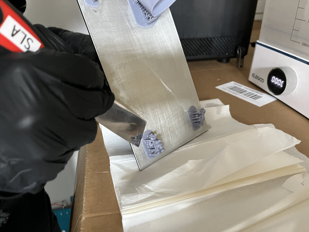
After the build plate is empty clean it thoroughly with isopropyl to avoid leftover resin.
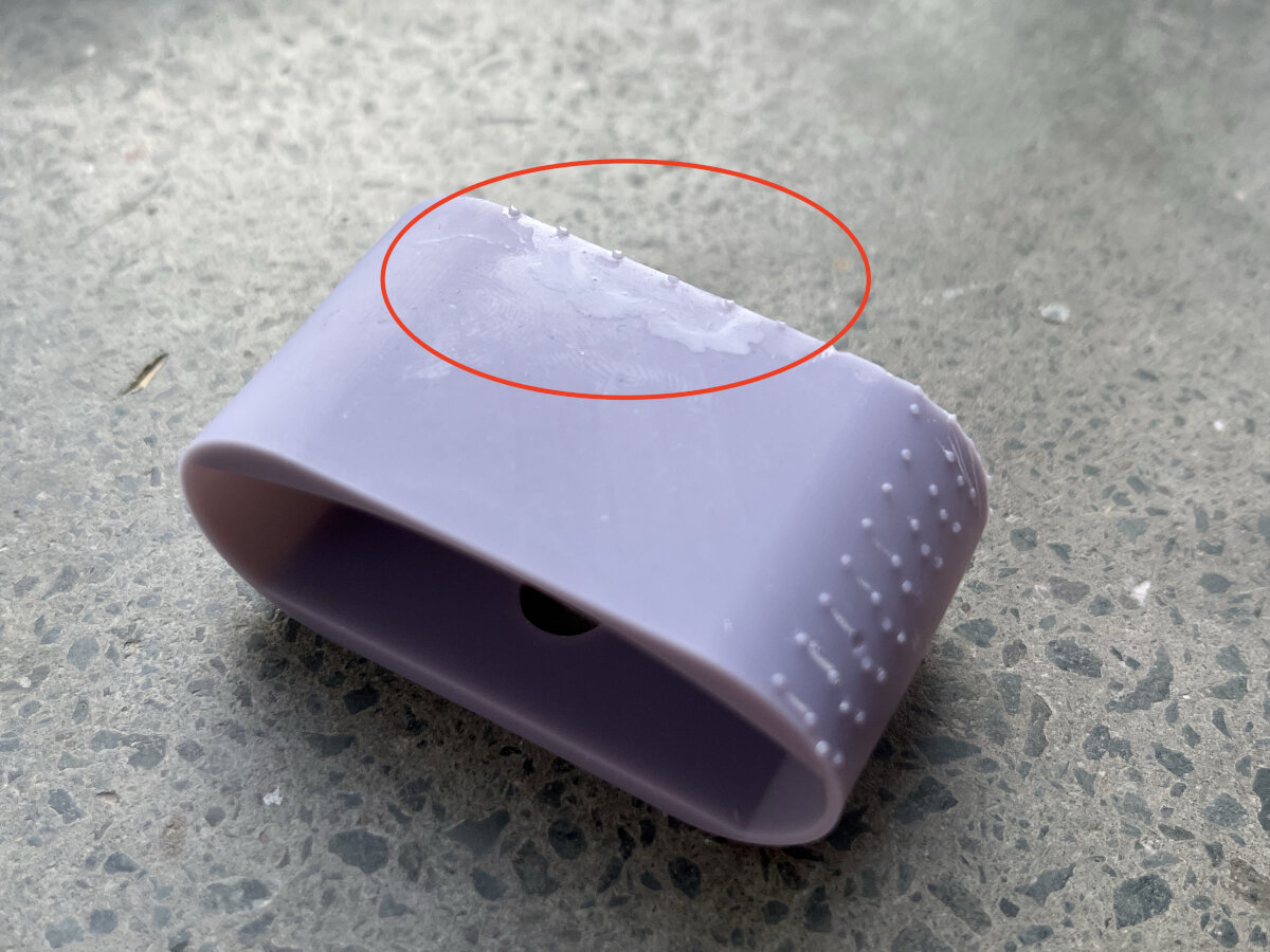
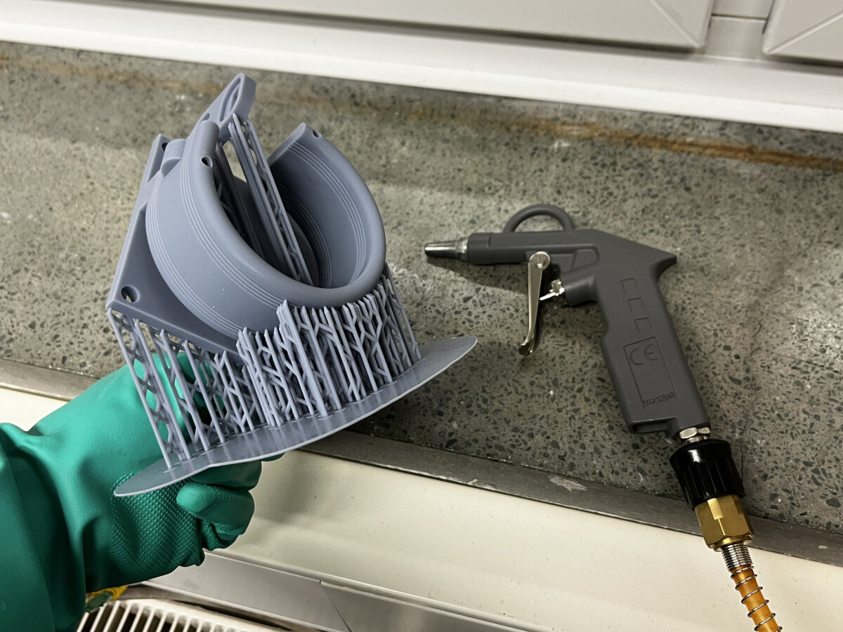
Optional step:
For cleaner results, use pressured air to remove the last remaining alcohol drops from the surface. If the small droplets stay on the surface, they can lead to white stains after curing.
Place and distribute all the parts evenly in the curing station.
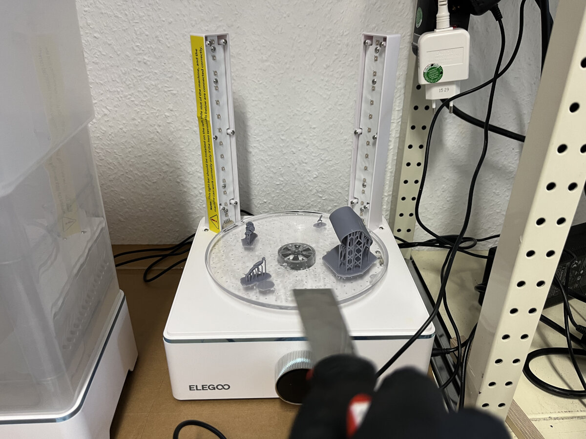
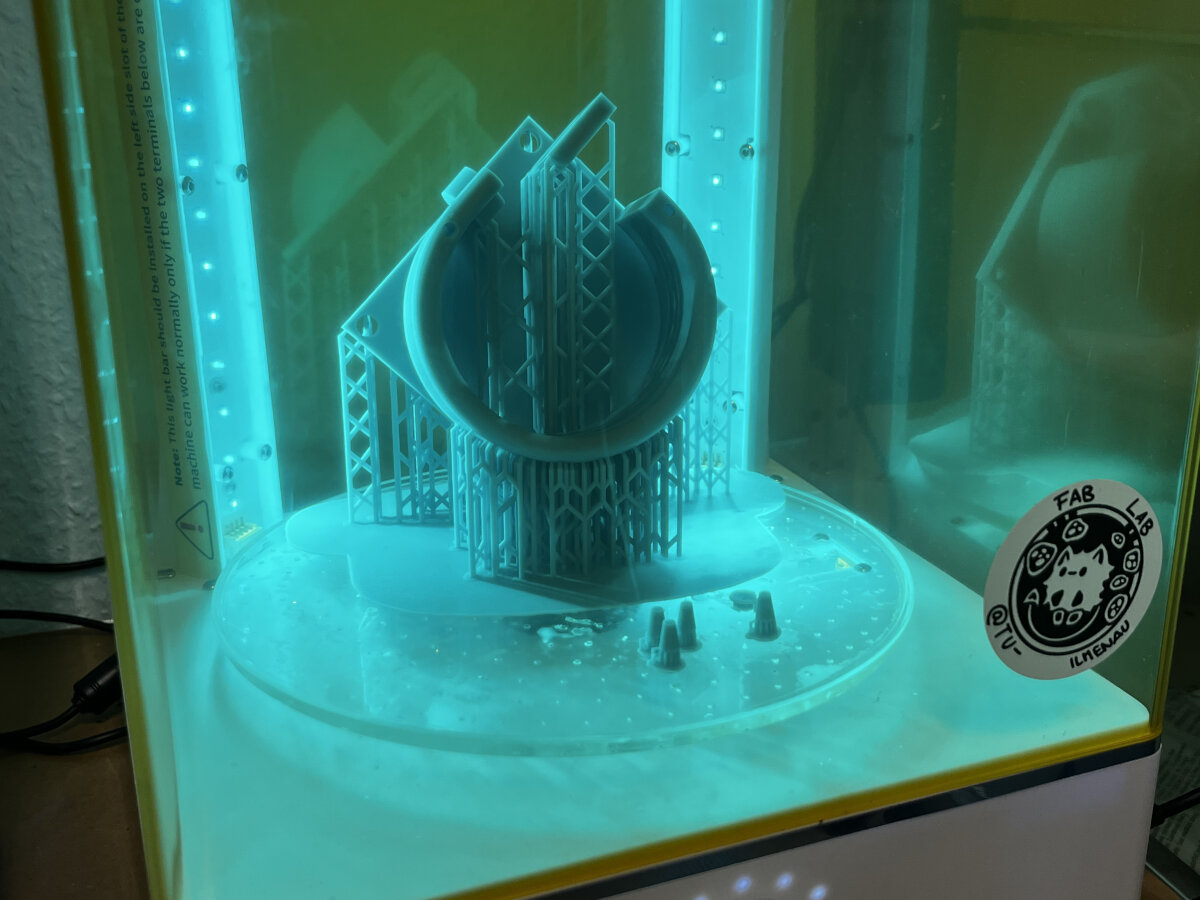
Let the part cure for 30 min or 1h for larger parts.
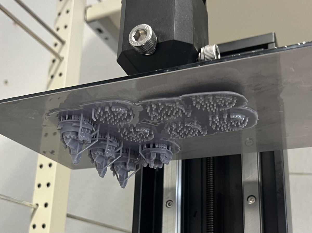
Post-processing
After the part is fully cured, it is usually necessary to remove the supports.
Depending on the type of support which was chosen in the slicing process, the damages after removing the supports will be clearly visible. In the shown example the ChituBox heavy support preset was used with a ball nose. The damage to the surface can be reduced by sanding. In this case it is recommended to remove just the stem of the support and leave the ball connection point between the part and the support attached to the part. The protruding pieces on the surface can be sanded down afterwords to achieve a smooth surface finish.
Files
Calibration/Quality Control
3D Scanning
Basic Scan - Rubber Eraser
25.02.2025
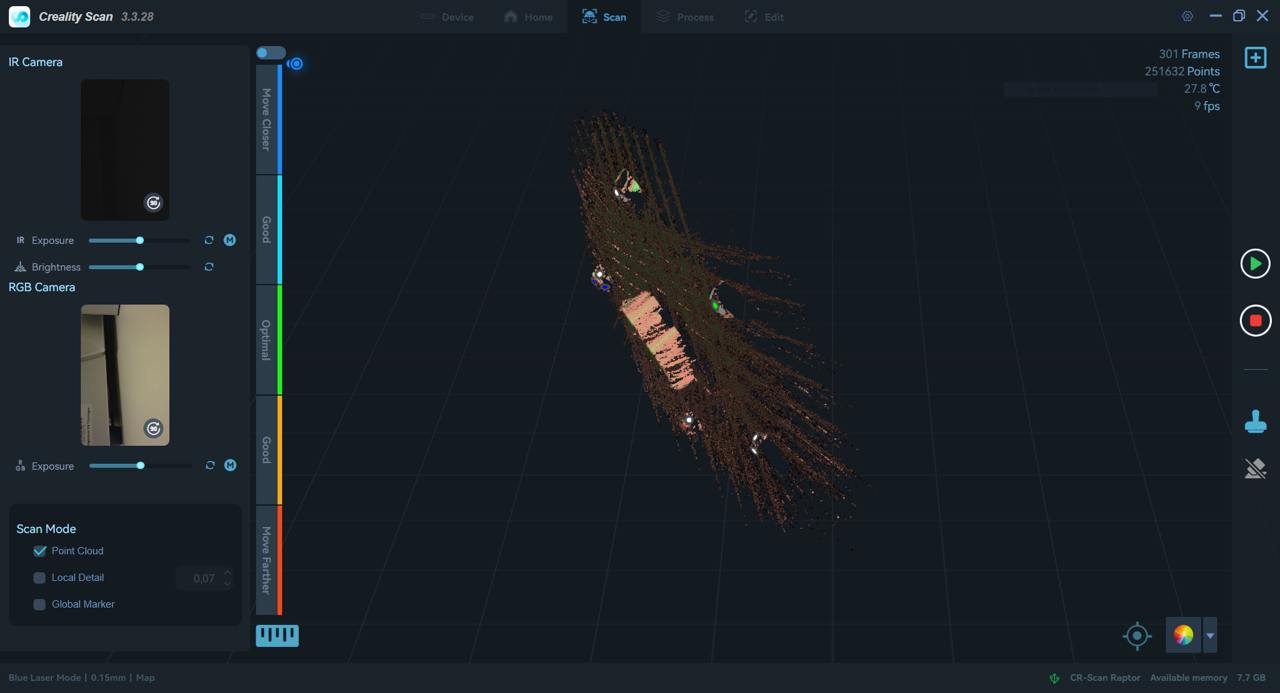
For the scanning process, I decided to scan a simple matte object with our Creality 3D scanner.
I chose a rubber eraser from my pencil case.
The software was already set up and configured by my team members.
I took the 3D-printed reflector markers, arranged them in a circle around the eraser, and did my first scan.
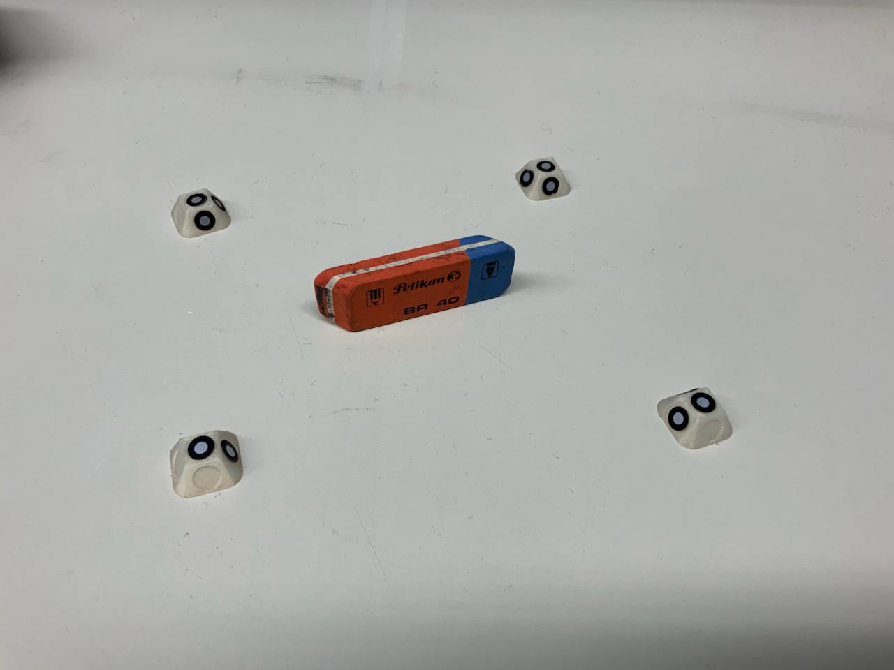
The first scan was bad because the scanner couldn't find the reflectors, and sometimes I was too close or too far away from the object.
The second scan turned out great, and I was pleased with how quickly I was able to create a simple scan.
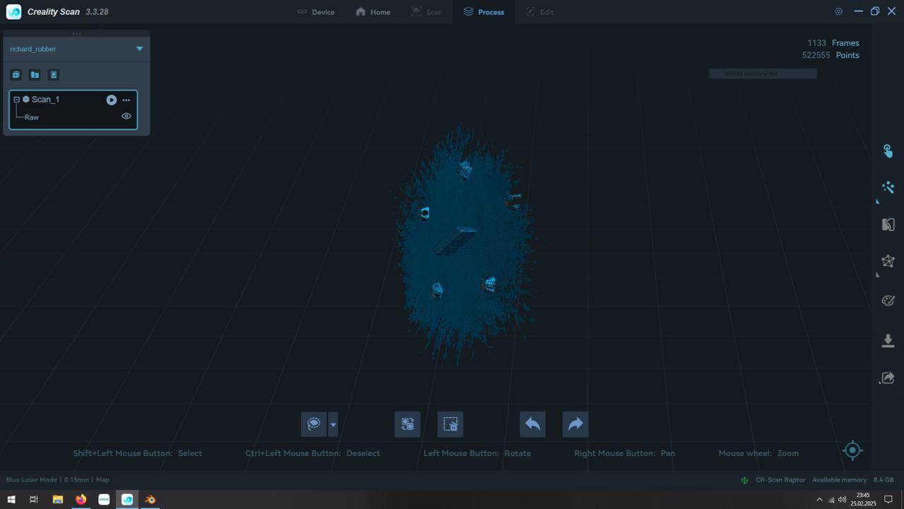
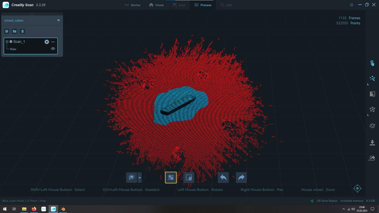
After exporting the files, I used my computer's built-in file viewer to check the files. The scan is not perfect but probably good enough to get some basic dimensions and angles of the model.
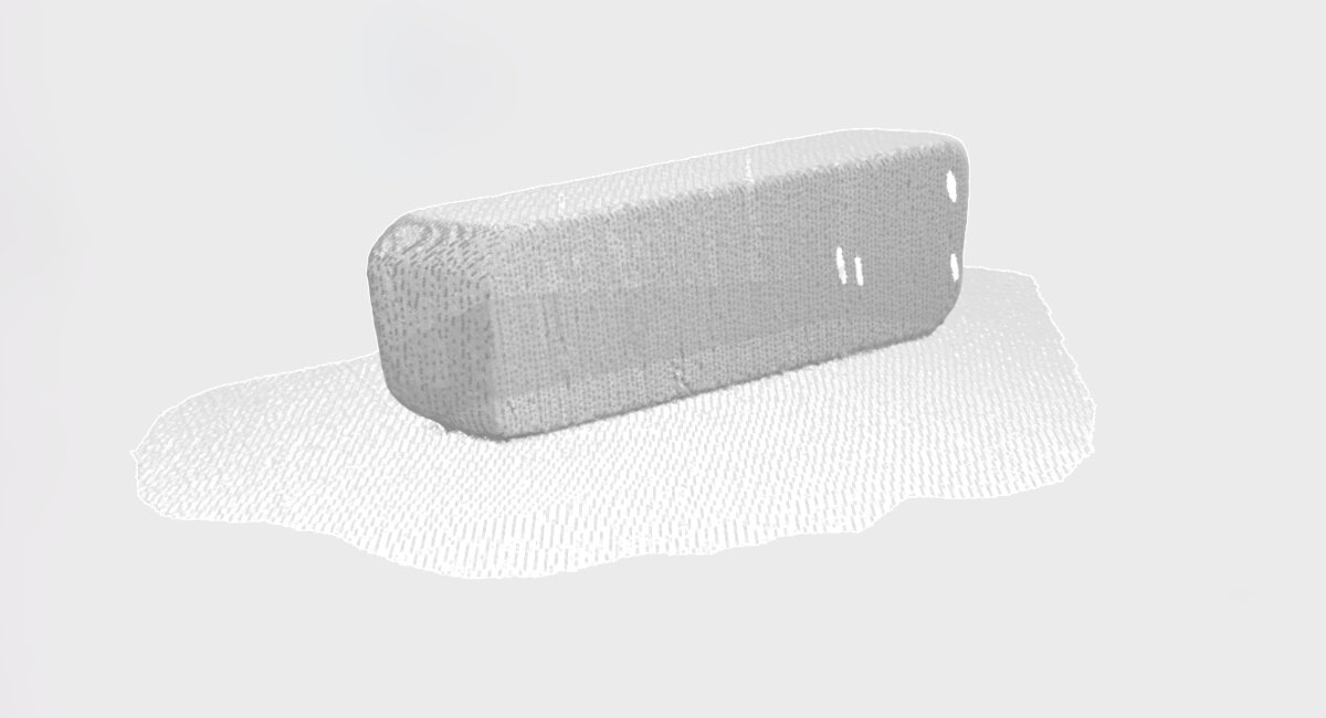
I expected the process to be much more difficult, but the software was intuitive and quite easy to use.
Files
I have exported the scans as .asc and .ply documents. They are hosted externally due to space limitations.
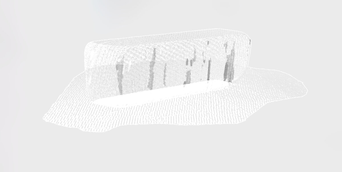
Intermediate Scan - Handlebar Stem
© 2026 Richard Draxler – Creative Commons Attribution Non Commercial
Source code hosted at gitlab.fabcloud.org