14. Interface and Application Programming
view Checklist from Nueval
- Linked to the group assignment page.
- Documented your process.
- Explained the Ul that you made and how you did it.
- Explained how your application communicates with your embedded microcontroller board.
- Explained any problems you encountered and how you fixed them.
- Included original source code (or a screenshot of the app code if that's not possible).
- Included a 'hero shot' of your application running & communicating with your board.
Group Assignment
The group assignment can be found here
Concept for the Hardware User Interface
Goal for this assignment:
- use serial communication between ATtiny board and PC
- change the LED color and brightness via a simple interface
- toggle for light color (red/white/off)
- slider for LED brightness (PWM ratio)
- slider for frequency (PWM frequency)
- use tkinter for the interface
C (Arduino flavor)
Serial Communication via UART
To learn more about serial communication I used a couple of examples from the Arduino Forum - Serial Input Basics.
Set up a Serial Connection with the board
Since my setup consists of two different hardware interfaces I need two software interfaces as well to communicate with the board.
- Arduino Uno for programming. It is connected via the serial port
/dev/cu.usbmodem111401 (Arduino Uno)in the Arduino IDE. Since the IDE only can connect to a single serial port a second application is neede to interface with the TX/RX connection of the ATtiny board. - Quentorres as USB to serial converter via the serial port
dev/cu.usbmodem70E3D603. This serial port is used to communicate between the ATtinys RX/TX interface and the computer. For sending and receiving commands from the ATtiny board CoolTerm is used. In the settings of CoolTerm it is configured in 'Line Mode' to allow entering full commands and sending them with enter.
Additional Serial Monitor
Additional Software (e.g. CoolTerm) is not needed, but very useful. Changing the serial port in the Arduino IDE after every upload to the communication serial port is possible, but just not practical for debugging.
Example 1 - Receiving single characters
Show Code: EX1_Receiving single characters
// ATtiny412, LUEDO MainBoard_V01

char receivedChar;
boolean newData = false;

void setup() {
  Serial.begin(9600);
  Serial.println("<Arduino is ready>");
}

void recvOneChar(){
  if (Serial.available() > 0) {
    receivedChar = Serial.read();
    newData = true;
  }
}

void showNewData() {
  if (newData == true) {
    Serial.print("This is just in ...");
    Serial.println(receivedChar);
    newData = false;
  }
}
void loop() {
  recvOneChar();
  showNewData();
}
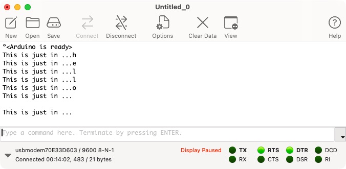
Serial monitor output from example 1 - Receiving single characters.
Learnings form the example code
- Serial communication sends a 'word' as single characters 'w' 'o' 'r' 'd'
- After every message there are two empty character send. These characters are non printing characters. The first character
\r(ASCII code: 13) describes the return to the beginning of the line (CR, Carriage Return). The second character\n(ASCII code: 10) describes a switch to a new line (LF, Line Feed). Sending the additional non-printing characters can be switched off in the serial monitor software CoolTerm.
Example 1_LED - Receiving single characters (Turning on LEDs)
Personal addition to the code from the previous example
I modified the example 1 to control the white and red LEDs on my LUEDO_MainBoard. Therfore I added a ledControl function to the existing code.
Show Code: EX1_LED_Receiving single characters
// ATtiny412, LUEDO_MainBoard_V01

// Output pins
const int ledPinW = 2;  // PA1: white LED pin
const int ledPinR = 3;  // PA2: red LED pin

char receivedChar;
boolean newData = false;

void setup() {
  pinMode(ledPinW, OUTPUT);
  pinMode(ledPinR, OUTPUT);
  Serial.begin(9600);
  Serial.println("<Arduino is ready>");
  Serial.println("'w' - turn on white led");
  Serial.println("'r' - turn on red led");
  Serial.println("'o' - turn off all leds");
}

void recvOneChar(){
  if (Serial.available() > 0) {
    receivedChar = Serial.read();
    newData = true;
  }
}

void showNewData() {
  if (newData == true) {
    Serial.print("received char: ");
    Serial.println(receivedChar);
    ledControl();
    newData = false;
  }
}

void ledControl() {
  if (receivedChar == 'w') {
   analogWrite(ledPinW,50);
  }
  if (receivedChar == 'r') {
   analogWrite(ledPinR,100);
  }
  if (receivedChar == 'o') {
   analogWrite(ledPinR,0);
   analogWrite(ledPinW,0);
  }
}

void loop() {
  recvOneChar();
  showNewData();
}
Controlling the LEDs with the LUEDO_MainBoard_V01 via the serial connection with the computer.
Learnings form the example code
- reducing software complexity by simple input codes is helpful (e.g. 'r' instead of 'red')
- use
constto define parameters that will not change (e.g. physical pinout)
Example 2 - Receiving several characters from the Serial Monitor
Expand Code: EX2_Receiving multiple characters
// Example 2 - Receive with an end-marker

const byte numChars = 32;
char receivedChars[numChars];     //with the brackets an array type char is created

boolean newData = false;          //indicates if data is revceived or not

void setup() {
  Serial.begin(9600);
  Serial.println("<ATtiny is ready>");
}

void recvWithEndMarker() {
  static byte ndx = 0;    //static byte is only visible for the function itself, it is only once initialized when
                          //the function is called for the first time, Index variable
  char endMarker = '\n';  //char is input as non-printable character, not as ASCII code
  char rc;                // buffer variable for reciving the char
  while (Serial.available() > 0 && newData == false) {
    rc = Serial.read();

    if (rc != endMarker) {
      receivedChars[ndx] = rc;  //writes the recieved char into the array
      ndx++;                    //incremet by one
      if (ndx >= numChars) {
        ndx = numChars - 1;     //protects the index variable to rise beyond the lenth of the array
      }
    }
    else {
      receivedChars[ndx] = '\0';  //terminate the string
      ndx = 0;
      newData = true;
    }
  }
}

void showNewData() {
  if (newData == true) {
    Serial.println("This just in ... ");
    Serial.println(receivedChars);
    newData = false;
  }
}


void loop() {
  recvWithEndMarker();
  showNewData();
}
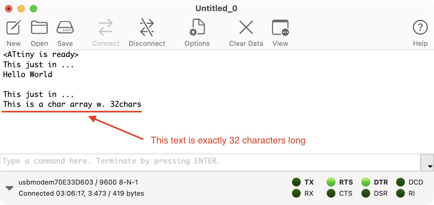
Learnings form the example code
- when working with limited hardware resources reducing storage size for input characters is necessary
- the serial connection is serial, that implies all characters are sent one after another
Example 4 - Receiving a single number from the Serial Monitor
In this example the char send via the serial monitor is converted to an integer.
Expand Code: EX4_Receiving single number
// Example 4 - Receive a number as text and convert it to an integer

const byte numChars = 32;
char receivedChars[numChars];   // an array to store the received data

boolean newData = false;

int dataNumber;                 // placeholder for the integer that is created form the char array

void setup() {
Serial.begin(9600);
Serial.println("<ATtiny is ready!>");
}

void recvWithEndMarker() {
    static byte ndx = 0;
    char endMarker = '\n';
    char rc;

    if (Serial.available() > 0) {
        rc = Serial.read();

        if (rc != endMarker) {
            receivedChars[ndx] = rc;
            ndx++;
            if (ndx >= numChars) {
                ndx = numChars - 1;
            }
        }
        else {
            receivedChars[ndx] = '\0'; // terminate the string
            ndx = 0;
            newData = true;
        }
    }
}

void showNewNumber() {
    if (newData == true) {
        dataNumber = 0;                     // default value is 0
        dataNumber = atoi(receivedChars);   // convertion form char array to int
        Serial.print("This just in ... ");
        Serial.println(receivedChars);
        Serial.print("Data as Number ... ");
        Serial.println(dataNumber);         // output the integer
        newData = false;
    }
}

void loop() {
recvWithEndMarker();
showNewNumber();
}
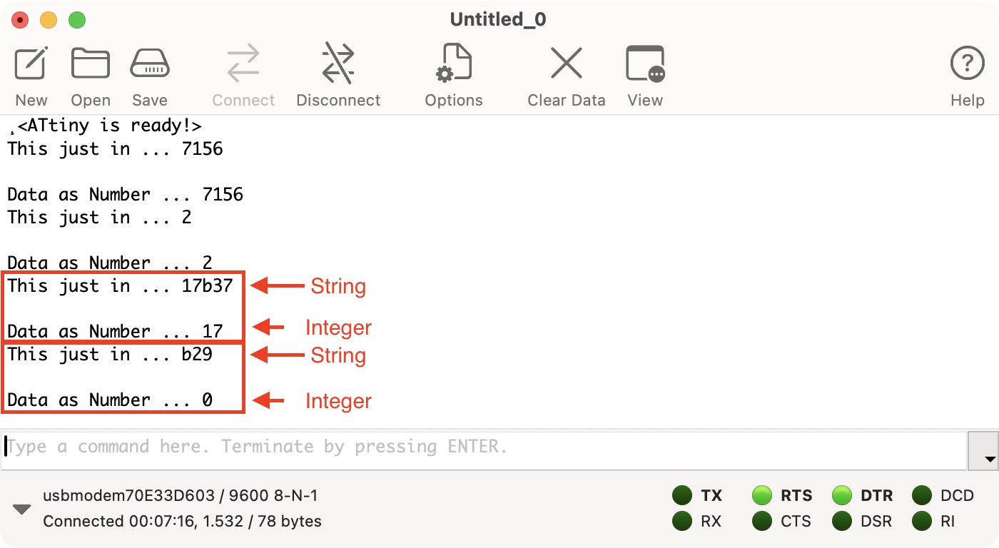
Learnings form the example code
- the
atoi()function converts mixed strings with numbers to integers - only leading numbers will be converted to integer
Python
Python version issue
Mac OS and other OSs can have different python versions. The currently used python version can always be checked with the command which python3. Depending on where and under which circumstances the command is executed the result varies since different versions of pythons are used in different places.
The different python versions on my system caused difficulties already in another project. For this assignment the problems started when I updated some of my packages. When I executed a python file with a tkinter nothing was displayed and I got an error message in the terminal window. Tkinter detected macOS 26.2 was detected as macOS 16 and therefor flagged as to old. An update to macOS 27.2 did not solve the issue.
| Python Install | Location | Version | Command to use this Version |
|---|---|---|---|
| System Python | /Library/Frameworks/Python.framework/Versions/3.14/bin/python3 | Python 3.14.10 | python3 |
| Homebrew Python | /opt/homebrew/bin/python3.15 | Python 3.15.2 | python3.15 |
When creating a virtual environment with pythonX -m venv venv_name it is important to choose the right python version of the venv. The version of the venv will match the version of the python install it was created with. For creating a 3.15.2 venv from the homebrew pyhton install run python3.15 -m venv venv_name this forces to the newer homebrew version.
Tkinter Interfaces
tkinter is a short form for TK interface. It is a python package that enables the user to program simple interfaces on common operating systems as Windows, MacOS and Linux. Tkdocs has a good documentation with tutorials which are accessibly for starters.
Installation and Verification
To install the tkinter python package on MacOS I ran this command:
brew install tcl-tk
To verify if everything is installed properly I checkt its function with:
python3 -m tkinter
This command opens up a GUI interface with the version number of the installation and two buttons.
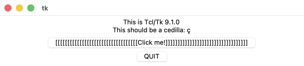
Tkinter test interface with version number and [click me!] button.
First steps
I followed a tutorial for a foot to meter converter from tkdocs to build the following app.
view Code: Foot to Meter Converter
from tkinter import *       # imports the standart GUI, import everything
from tkinter import ttk     # provides themed widgets (buttons, labels, entries)

def calculate(*args):                       # this is a function in python called "calculate"
    try:                                        # try to convert variable feet to meters
        value = float(feet.get())               # read feet var, convert to float
        meters.set(round(0.3048 * value, 4))    # set the meters var
                                                # multiply feet float * 0.3048 and round to 4 digits
    except ValueError:
        pass

root = Tk()                         # creates the main window
root.title("Feet to Meters")        # title of the window

mainframe = ttk.Frame(root, padding=(3, 3, 12, 12))     # ttk.Frame defines a container to hold widgets (e.g button, dropdown, ...)
                                                        # used the theme version of tk, mainframe is a child of the root window
                                                        # defines padding in px: top=3, left=3, bottom=12, right=12
mainframe.grid(column=0, row=0, sticky=(N, W, E, S))    # places the mainframe item in the main window at grid pos. 0,0
                                                        # sticky allows resizing the window, items stick to all sides of the window

feet = StringVar()                                              # feet is a variable form the type String, stors length in feet
                                                                    # Note: feet needs to be an instance of StringVar class, cant be a regular python var
feet_entry = ttk.Entry(mainframe, width=7, textvariable=feet)   # ttk.Entry creates a text input field in the mainframe with width 7
                                                                # input is stored in var feet
feet_entry.grid(column=2, row=1, sticky=(W, E))                 # places the entry box in the grid at pos (2,1)

meters = StringVar()                                            # meters is a variable form the type String, stores lenght in meters
ttk.Label(mainframe, textvariable=meters).grid(column=2, row=2, sticky=(W, E))  # lable is a output text, that can change (result of cacl)

ttk.Button(mainframe, text="Calculate", command=calculate).grid(column=3, row=3, sticky=W)

ttk.Label(mainframe, text="feet").grid(column=3, row=1, sticky=W)
ttk.Label(mainframe, text="is equivalent to").grid(column=1, row=2, sticky=E)
ttk.Label(mainframe, text="meters").grid(column=3, row=2, sticky=W)

root.columnconfigure(0, weight=1)                   # frame should expand to fill any extra space if window is resized horizontal
root.rowconfigure(0, weight=1)                      # frame should expand to fill any extra space if window is resized horizontal
mainframe.columnconfigure(2, weight=1)              # just the mainframe column should adapt its size
for child in mainframe.winfo_children():            # adds to every item in mainframe a padding of 5 pixel in x and y dir
    child.grid_configure(padx=5, pady=5)

feet_entry.focus()                                  # cursor starts blinking in input field after startup
root.bind("<Return>", calculate)                    # pressing "Return" is mapped to "calculate"button

root.mainloop()
from tkinter import * imports the whole Tk library and adds tkk for themed widgets. For using the themed tk version it is necessary to prefix everything with tkk. e.g tkk.Entry(...) for the themed version. To call the standard version just Entry(...) would be used.
The mainframe is a widget. It will hold the content of the UI. The parent of the mainframe widget is the main application window. That's why it is referenced in the code as root. When creating a widget, additional parameters can be pass to override default parameters e.g. padding.
mainframe.grid places the mainframe in the main application window. The variable feet and meters are both from the type String. The command ttk.Entry creates a themed tk input box that can be placed with the same attributes as the mainframe. The other widgets (button and label) are created and placed in exactly the same way. The for loop ads a padding of 5 px in x and y to each widget.
The function calculate is a normal python function, and it does the conversion between feet and meters. It is important, that the variables for feet and meters are an instance of the StringVar class to allow for automatic updating the text.
After running the foot to meter converter with the command python3 feet_to_meter.py the following window appeared.
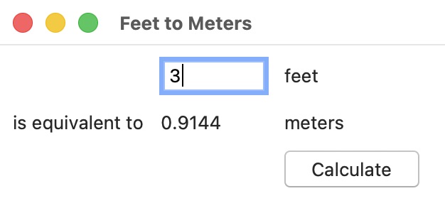
GUI built with tkinter and the ttk themed library. The example feet to meter converter can be resized and navigated with the TAB and ENTER key.
General Layout Mechanisms
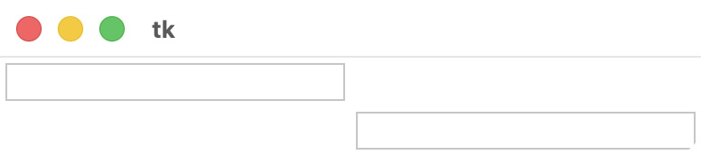
After analyzing the sample code I created a couple of tests to verify the general mechanisms of widget and window layout in tkinter.
Minimal Configuration
from tkinter import *
from tkinter import ttk

root = Tk()
root.mainloop()
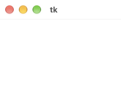
Widgets in the Grid
from tkinter import ttk

root = Tk()

mainframe = ttk.Frame(root)
mainframe.grid(column=0, row=0)

feet_entry = ttk.Entry(mainframe)
feet_entry.grid(column=1, row=1)

meter_entry = ttk.Entry(mainframe)
meter_entry.grid(column=2, row=2)

root.mainloop()
Automatic Content Resizing
from tkinter import *
from tkinter import ttk

root = Tk()

mainframe = ttk.Frame(root)
mainframe.grid(column=0, row=0, sticky =(N, W, E, S))

feet_entry = ttk.Entry(mainframe, width=7)
feet_entry.grid(column=1, row=1, sticky=(W, E))

meter_entry = ttk.Entry(mainframe, width=7)
meter_entry.grid(column=2, row=2, sticky=(W, E))

root.columnconfigure(0, weight=1)
root.rowconfigure(0, weight=1)
mainframe.columnconfigure((1,2), weight=1)
mainframe.rowconfigure((1,2), weight=1)

root.mainloop()
My first GUI: LUEDO PWM Light Control (GUI)
The general goal for the project is listed above in the section Concept for the Hardware User Interface. In this section I will focus just on the UI elements and not the communication with a serial port it is covered in the section Serial Communication via UART. My first version of the GUI will use a single text input field which mimics a typical serial monitor command line. The serial port and baud rate will be fixed in the header of the code.
view Code: LUEDO PWM Light Control (Serial Terminal)
from tkinter import *
from tkinter import ttk

serialPort = "com XY"
baudRate = "9600"

root = Tk()
root.title("LUEDO PWM Light Control")

mainframe = ttk.Frame(root, padding=(5, 5, 5, 5))
mainframe.grid(column=0, row=0, sticky=(N, W, E, S))

ttk.Label(mainframe, text="Serial Port:").grid(column=1, row=1, sticky=(W, E))
ttk.Label(mainframe, text=serialPort).grid(column=2, row=1, sticky=(W, E))

ttk.Label(mainframe, text="Baud Rate:").grid(column=1, row=2, sticky=(W, E))
ttk.Label(mainframe, text=baudRate).grid(column=2, row=2, sticky=(W, E))

ttk.Label(mainframe, text="Command:").grid(column=1, row=3, sticky=(W, E))
command_entry = ttk.Entry(mainframe, width=7)
command_entry.grid(column=2, row=3, sticky=(W, E))

root.columnconfigure(0, weight=1)
root.rowconfigure(0, weight=1)
mainframe.columnconfigure((1,2), weight=1)
#mainframe.rowconfigure((1,2,3), weight=1)

for child in mainframe.winfo_children():            # adds to every item in mainframe a padding of 5 pixel in x and y dir
    child.grid_configure(padx=5, pady=5)

command_entry.focus()                                  # cursor starts blinking in input field after startup

root.mainloop()
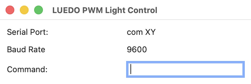
First simple GUI layout for the LUEDO PWM Light Control. The window is resizable, and the input box is highlighted immediately after opening the program.
Serial Communication via UART
For the Serial communication I decided to use the standard serial communication package for python called pySerial. It allows the python code to communicate with my serial port (in this case my Quentorres as a USB-to-Serial converter).
Installation of pySerial
I installed the python package pySerial in a virtual environment.
python3.15 -m venv .venv
source .venv/bin/activate
pip install pyserial
Use Homebrew Pyhton version
It is important to type pyhton3.15 to force the creation with the brew python version and not the systems' python.
The virtual environment needs to be activated every time the pySerial package is needed. Use the command deactivate to deactivate the venv.
Find Connected Serial Devices
To find connectes serial devices on MacOS use the following command:
ls /dev/cu*
An output example could look like this:
/dev/cu.Bluetooth-Incoming-Port /dev/cu.usbmodem70E33D603
/dev/cu.debug-console /dev/cu.usbserial-110
In this case the Quentorres is the cu.usbmodem70E33D603 device.
First Example
This first example demonstrates, that its possible to control an ATtiny mcu board with the python. To establish a communication between the python code and the board the pySerial package is needed.
Additonal Serial Monitor needed
The startup sequence of the code can not be controlled with the python script in this version. Therefore, CoolTerm is used to control the startup sequence before the python script is executed.
view Code: pySerial_test.py
import serial
import time

ser = serial.Serial('/dev/cu.usbmodem70E33D603', 9600, timeout=1)     # open the serial port
print(ser.name)                         # output on the terminal: which port was really used

for i in range(0, 5):
    ser.write(("c"+'\r'+'\n').encode())
    time.sleep(0.5)
    ser.write(("1"+'\r'+'\n').encode())     # send as string
    time.sleep(0.5)
    ser.write(("c"+'\r'+'\n').encode())
    time.sleep(0.5)
    ser.write(("1"+'\r'+'\n').encode())
    print(i)

#ser.write(b"1\r\n")                    # send as bytes
time.sleep(0.1)                         # IMPORTANT, otherwise the port is closed before the message is sent
ser.close()
The package pySerial allows interacting with the ATtiny boards via UART and a USB-to-Serial adapter (Quentorres).
This code opens the serial port /dev/cu.usbmodem70E33D603 with a baud rate of 9600 and writes a number 1 and the non printing characters \r and \n to the serial port.
When connected to the LUEDO MainBoard via the USB-to-Serial adapter the red LED will turn on. The LUEDO MainBoard_V01 runs the code written in the Output Assignment - Week 10. Originally the C code was designed to be controlled via a serial monitor e.g. Arduino IDEs Serial Monitor or CoolTerm now it is controlled by the pySerial python script.
My first CLI: LUEDO PWM Light Controll (CLI)
The LUEDO MainBoard and its PWM output can also be controlled via a CLI.
View Code: LUEDO_PWM_Light_Control_CLI
# This program can be used to controll the LUEDO MainBoard and LightBoard via a CLI
# IMPORTANT: Use the CoolTerm Serial Monitor first to controll the startup frequence

import serial
import time

print("LUEDO PWM Light Control CLI")

ser = serial.Serial('/dev/cu.usbmodem70E33D603', 9600, timeout=1)     # open the serial port
print(ser.name)                         # output on the terminal: which port was really used

for i in range (0, 5):
    print("Input parameter: 'c' change color; 'f' change frequency; 'd' change duty cycle")
    parameter = input()

    if parameter == "c":
        ser.write(("c"+'\r'+'\n').encode())
        time.sleep(0.1)                       # wait for the serial connecion
        print("Press 0 for white or 1 for red")
        color = input()
        ser.write((color+'\r'+'\n').encode())

    if parameter == "f":
        ser.write(("f"+'\r'+'\n').encode())
        time.sleep(0.1)
        print("Input frequency in Hz")
        frequency = input()
        ser.write((frequency+'\r'+'\n').encode())

    if parameter == "d":
        ser.write(("d"+'\r'+'\n').encode())
        time.sleep(0.1)
        print("Input duty cycle in %")
        duty_cycle = input()
        ser.write((duty_cycle+'\r'+'\n').encode())

    time.sleep(0.1)

time.sleep(0.1)                         # IMPORTANT, otherwise the port is closed before the message is sent
ser.close()
Additonal Serial Monitor needed
The startup sequence of the code can not be controlled with the python script in this version. Therefore, CoolTerm is used to control the startup sequence before the python script is executed.
First CLI for the LUEDO MainBoard_V01. The CLI needs CoolTerm (upper window) to handle the startup sequence. The lower window is the Mac Terminal which is used to start and control the python scrip. In the second part the LED frequency is in sync with the 30fps of the video resulting in a fade effect.
Serial Communication and GUI
In this section I combine the learnings from all section in this page to create a GUI that can control the PWM parameters. The version shown below could be called a GUI, but it is more a GUI interface for a CLI.
View Code: LUEDO_PWM_Light_Control.py
from tkinter import *
from tkinter import ttk
import serial               # imports the pySerial package
import time                 # needed for time.sleep


serialPort = "/dev/cu.usbmodem70E33D603"
baudRate = "9600"

ser = serial.Serial('/dev/cu.usbmodem70E33D603', 9600, timeout=1)     # open the serial port

def serial_send(*args):
    try:
        text = message.get()
        ser.write(text.encode('utf-8'))
        ser.write(('\r'+'\n').encode())
        time.sleep(0.5)
    except ValueError:
        pass

root = Tk()
root.title("LUEDO PWM Light Control")

mainframe = ttk.Frame(root, padding=(5, 5, 5, 5))
mainframe.grid(column=0, row=0, sticky=(N, W, E, S))

ttk.Label(mainframe, text="Serial Port:").grid(column=1, row=1, sticky=(W, E))
ttk.Label(mainframe, text=serialPort).grid(column=2, row=1, sticky=(W, E))

ttk.Label(mainframe, text="Baud Rate:").grid(column=1, row=2, sticky=(W, E))
ttk.Label(mainframe, text=baudRate).grid(column=2, row=2, sticky=(W, E))


ttk.Label(mainframe, text="Command:").grid(column=1, row=3, sticky=(W, E))

message = StringVar()
command_entry = ttk.Entry(mainframe, width=7, textvariable=message)
command_entry.grid(column=2, row=3, sticky=(W, E))

ttk.Button(mainframe, text="Send Command", command=serial_send).grid(column=2, row=4, sticky=W)

root.columnconfigure(0, weight=1)
root.rowconfigure(0, weight=1)
mainframe.columnconfigure((1,2), weight=1)
#mainframe.rowconfigure((1,2,3), weight=1)

for child in mainframe.winfo_children():            # adds to every item in mainframe a padding of 5 pixel in x and y dir
    child.grid_configure(padx=5, pady=5)

command_entry.focus()                                  # cursor starts blinking in input field after startup

root.mainloop()
Final result: A GUI that shows the preset serial port and baud rate with a small embedded command window to send commands to the LUEDO MainBoard_V01.
© 2026 Richard Draxler – Creative Commons Attribution Non Commercial
Source code hosted at gitlab.fabcloud.org