09. Input Devices
view ideas
- LUEDO capacitiv foil on the inside of the housing to redout the hands proximity to the lamp
- LUEDO hall sensors for detecting the mount
- noise reduction, avoid flickering of the LEDs
view checklists
- Checklist: personal
- DeepL check spelling, grammar
- GPTcheck for better markdown
- Checklist: Nueval:
- Linked to the group assignment page.
- Documented what you learned from interfacing an input device(s) to your microcontroller and optionally, how the physical property relates to the measured results.
- Documented your design and fabrication process or linked to the board you made in a previous assignment.
- Explained the programming process(es) you used. Explained any problems you encountered and how you fixed them.
- Included original design files and source code.
- Included a 'hero shot of your board.
Group assignment
Here is the link to the group assignment about Input Devices.
MagSafe Magnet Array
Official MagSafe Design Guidelines
Since the Luedo Light should be compatible and charged with the MagSafe/Qi2 magnetic wireless charging standard. I searched for the official documentation by Apple and found the Accessory Design Guidelines which helped me with the magnet configuration for the Luedo light.
In chapter 42.1 the relevant information starts.
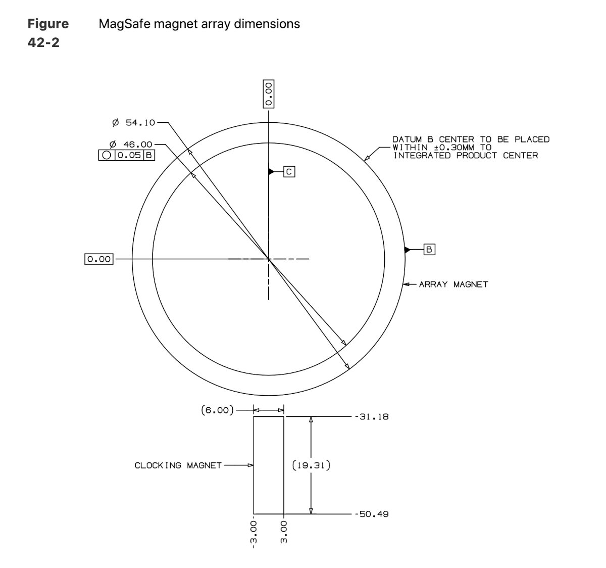
Magnet array information from the Apple accessory design guideline.
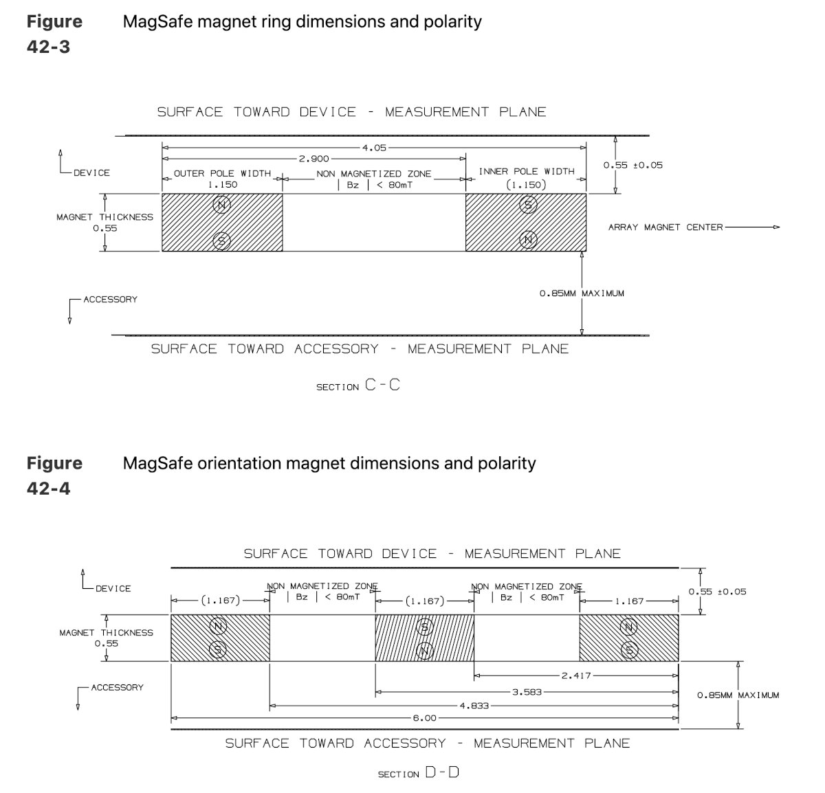
Magnet polarity and position in the magnet array from the Apple accessory design guideline.
The magnet configuration for my LUEDO light should share the same layout to allow for interoperability with the charging pucks.
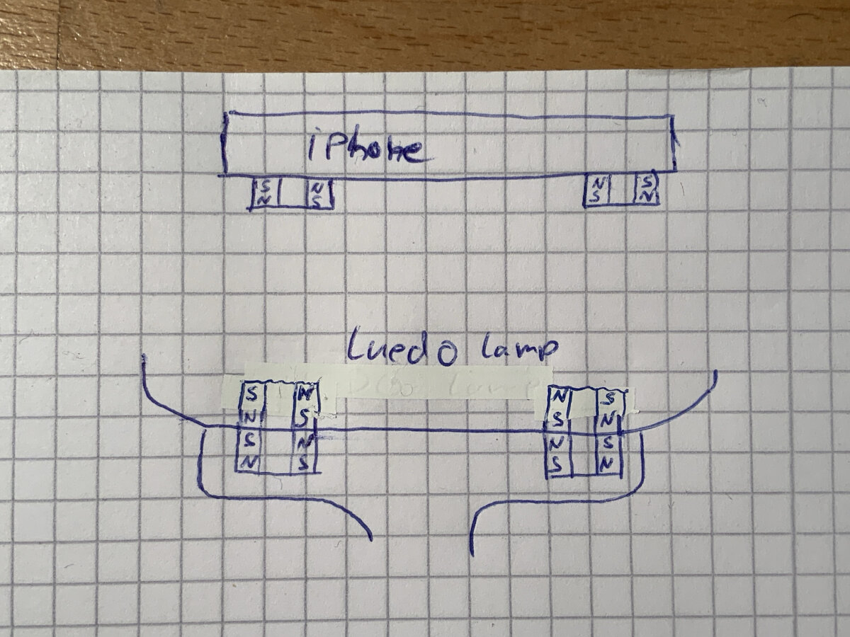
Magnet position in the LUEDO lamp.
Interesting additional links:
- Kavi's Blog
- Pitaka case implementation with extra magnets
Hall Sensors
Different types
Overview:
| Sensor Type | Analog Hall Sensor | Digital Hall Sensor | Multi Axis Sensor |
|---|---|---|---|
| Magnetic Type | Polar, single axis | Unipolar, single axis | Polar, three axis |
| Measuring Type | continuous (analog readout) | binary (digital readout) | continuous (I2C readout) |
| Datasheet | A1324 - Datasheet | A3144/ES3144EUA - Datasheet | TLE493D-A2B6 - Datasheet |
| Application | A3144 - Arduino example |
Analog Hall Sensor
listed in the FabInventory
An analog hall sensor returns the measured magnetic field as a analog voltage on one of its pins
Magnetic Type: Polar, single axis
Measuring Type: continuous (analog readout)
Datasheet: A1324 - Datasheet
Application:
Digital Hall Sensor
not listed in the FabInventory
For my original prototype of the Luedo lamp which I build before the FabAcademy I used digital unipolar hall sensors. It was the easiest type of sensor since it sends a high or low value no matter of type of magnetic field.
Magnetic Type: Unipolar, single axis
Measuring Type: binary (digital readout)
Datasheet: A3144 - Datasheet
Application: A3144 - Arduino example
Multi Axis Sensor
listed in the FabInventory
Magnetic Type: Polar, three axis
Measuring Type: continuous (I2C readout)
Datasheet: TLE493D-A2B6 - Datasheet
Application:
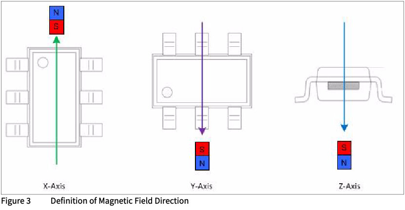
In the datasheet chapter 2.3 is the direction of the magnetic field defined.
Hall sensor for LUEDO Lamp
In the original mockup which I build before the FabAcademy I used simple unipolar digital hall sensors. After testing the original mockup I ran into flickering issues with the light and sometimes the issue, while snapping the light on the wrong light color was emitted since one of the unipolar digital hall sensors got triggered by the MagSafe alignment magnets.
For this reason I decided to improve the design and rely on two hall sensors which need a specific readout on both sensors to verify the lamps position. With this design choice it should be impossible to trigger the hall sensors with the MagSafe alignment magnets.
For the Luedo lamp in its development state I choose to use two analog hall sensors to adjust later in the software form which point the sensor should be triggered. The analog readout value will depend on the distance and position between the sensor and the magnet. These parameters are not set due to possible material thickness changes and repositioning for a better final design. The needed values can later be adjusted in the software.
Input Boards - Ludeo SensorBoard_V0.1
For the Luedo SensorBoard_V01 I decided to create an analog and a digital version for comparing the two sensors for my application.
LUEDO SensorBoard_V01_A (Analog Hall Sensor)
Design
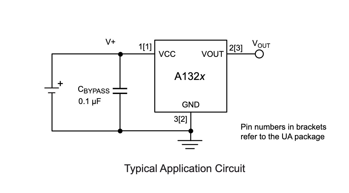 I took the typical application diagram and created my own circuit
- small signal voltage developed across the Hall element
- drift is induced by thermal and mechanical stress
- drift can be compensated with a chopper stabilization technique when needed
The header on the board matches the pinout of my LUEDO DevBoard which was design during the Electronics Design Assignment. Therefor the DevBoard can be used for testing and selection of the right sensor type.
The PCB design of the LUEDO SensorBoard_V01_A is quiet simple.
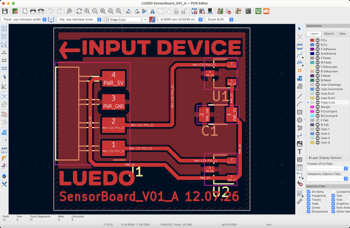
PCB layout for the analog LUEDO SensorBoard_V01_A.
Production
The production of the board is described in detail in the Electronics Production Assignment in the section PCB Production: UV Laser.
Here are the design files needed for the LUEDO SensorBoard_V01_A.
LUEDO SensorBoard_V01_A-F_Cu.gbr
LUEDO SensorBoard_V01_A-Edge_Cuts.gbr
Here are the production files needed for the LUEDO SensorBoard_V01_A.


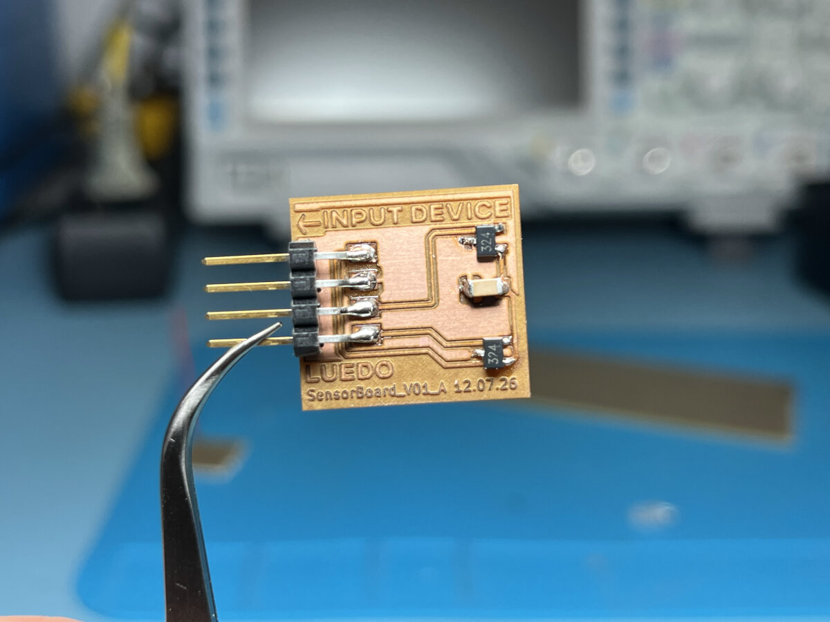
Final board after stuffing with components.
Testing
Serial Monitor Script
For the testing my LUEDO DevBoard_V01 is used, and the following code is flashed to the board.
int analogPin = 0;    // hall sensor pin
int val = 0;          // saves the current sensor value

void setup() {
  Serial.begin(115200);     // starts the serial connection
}

void loop() {
  val = analogRead(analogPin);    // read the sensor value
  Serial.println(val);            // send sensor value via serial
  delay(100);
}
The code uses the hardware pin 2 as an input Pin for the signal from the hall sensor and hardware pin 7 is configured by default as a TX sending pin (serial).
| Application | Hardware Pin | Port Pin | Software Pin |
|---|---|---|---|
| Hall Sensor Input | 2 | PA4 | 0 |
| Serial Output TX | 7 | PB2 | 5 |
The script can be flashed onto the board with the modified Arduino UNO as a programmer. Unfortunately this hacked programmer can't pass through the ATtinys serial connection to the PC. Therefore, the UNO needed to be re-flashed every time it is used as a programmer or as a serial pass through. To avoid this process I set up my Quentorres programmer as my receiver for the serial connection.
Arduino IDE Serial monitor reading out the hall sensor signal from the ATtiny. The analog sensor represents the variable magnetic field as a value. This value is 507 when no magnetic field is present, and 3 for maximum field in one direction and 1011 for the maximum magnetic field in the other direction (shown in the second part of the video).
The Quentorres programmer on the left is used to receive the serial signal from the ATtiny. The Arduino UNO on the right is used to flash and power the ATtiny board. The yellow cable connects the tiny's TX pin with the Quentorres' RX pin.
Note
Before flashing new software to the ATtiny board the "Port" in the Arduino IDE needs to be changed to the adjacent configuration. The same applies for the configuration as a serial monitor. Therefore, the Quentorres needs to be set as a main device.
Magnetic Flux Direction represented as Colors
The analog sensor on the SensorBoard_V01_A is directional, therefore it has the ability to detect the direction of the magnetic flow. This feature is crucial for the LUEDO lamp to distinguish between the magnet sensor array (mounting and charging) and the information magnets, which control the emitted light color.
int analogPin = 0;    // hall sensor pin
int val = 0;          // saves the current hall sensor value
int ledWhitePin = 8;  // white led pin
int ledRedPin = 9;    // red led pin
int brght = 0;

void setup() {
  Serial.begin(115200);   // starts the serial connection
}

void loop() {
  val = analogRead(analogPin);    // read the sensor value
  Serial.println(val);            // send sensor value via serial
  if (val >= 507) {
    val = val - 507;
    brght = val/2;
    analogWrite(ledWhitePin, brght);
    delay(10);
  }
  else{
    val = 256 - (val/2);
    brght = val;
    analogWrite(ledRedPin,brght);
    delay(10);
  }
  analogWrite(ledWhitePin, 0);
  analogWrite(ledRedPin, 0);
}
Depending on the flux direction through the analog sensor the color is either white or red.
LUEDO SensorBoard_V01_D (Digital Hall Sensor)
The digital version of the SensorBoard should contain a digital hall sensor which is connected to the ATtiny via the I2C protocol. The specific sensor from the FabInventory is the TLE493D-A2B6 it has the ability to measure the magnetic field in X, Y and Z directions. A directional analysis is most likely not needed for the final LUEDO light, but I could help with the magnet arrangement design in the future.
Design
For the circuit design I used the standard application circuit form the datasheet.
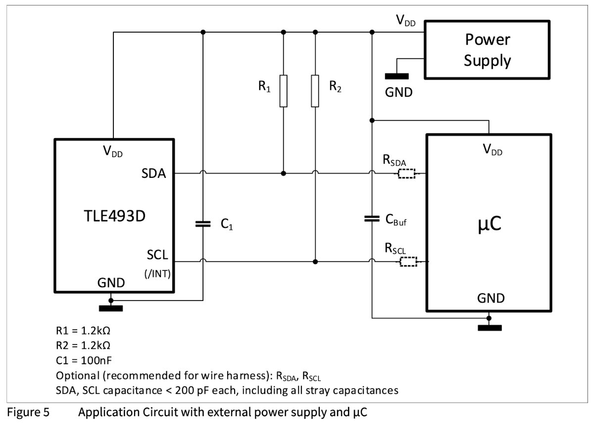
Standard application sheet from the datasheet (section 2.5)
Work in progress
Key Learnings
- connecting analog sensors to the ATtiny is easy
- raw signals require post-processing
- determining the direction of the magnetic field is helpful for the LUEDO light
© 2026 Richard Draxler – Creative Commons Attribution Non Commercial
Source code hosted at gitlab.fabcloud.org