16. Wildcard Week
view Checklist Personal
- DeepL check spelling, grammar
- repair file links, replace .png -> .jpg; .mov -> .mp4, .webp
- remove audio from video, compress
- GPT check for better markdown
- compress all files before push
- gather info about volume requirements for each component
- design housing
- design reflector
- FDM print as high quality PLA part
- SLA print as high quality part
- cover with conductive spray
- select plating material
- electroplate surface
- read DIN33958, extract relevant information
- select LED from Osram with ~150 lm
view Checklist Nueval
- Documented the workflow(s) and process(es) you used
- Explained how your process is not covered in other assignments. Described problems encountered (if any) and how you fixed them
- Included original design files and source code
- Included 'hero shot' of the result
Electroplated Reflector
For the Wildcard Assignment, I chose to design a custom reflector for my LUEDO lamp. The goal was to design the reflector so that the emitted light would meet the requirements for road traffic in Germany. The "wild" part of this project were simulating the light beams and electrogalvanically coating the 3D-printed part.
Research
Vocabulary
The most important basic terms are explained again here: We are brighter - Light measurement terms
Luminous Intensity Distribution Curve
source: Trilux - Luminous Intensity Distribution Curve
source: Saxonia Licht - Lichtverteilungskurve
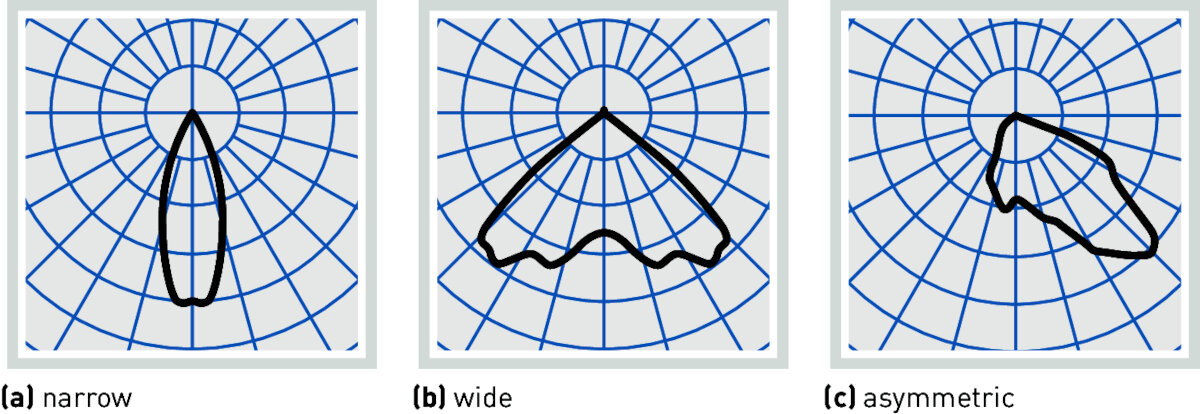
Luminous intensity distribution curves of direct-distribution luminaires
source: Trilux
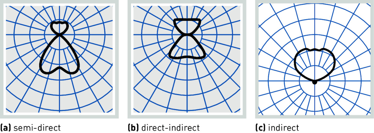
Luminous intensity distribution curves with indirect portion
source: Trilux
- Visual representation of the light distribution of a light source
- Polar coordinate system
- Luminous intensity as a function of the beam angle
- for comparability, the LIDC is related to 1000 lm luminous flux
- Differentiation between A, B and C sectional planes
- normally shown as C sectional plane, directly through the luminaire
- Intersection with the circle results in luminous intensity in cd
Luminance Distribution
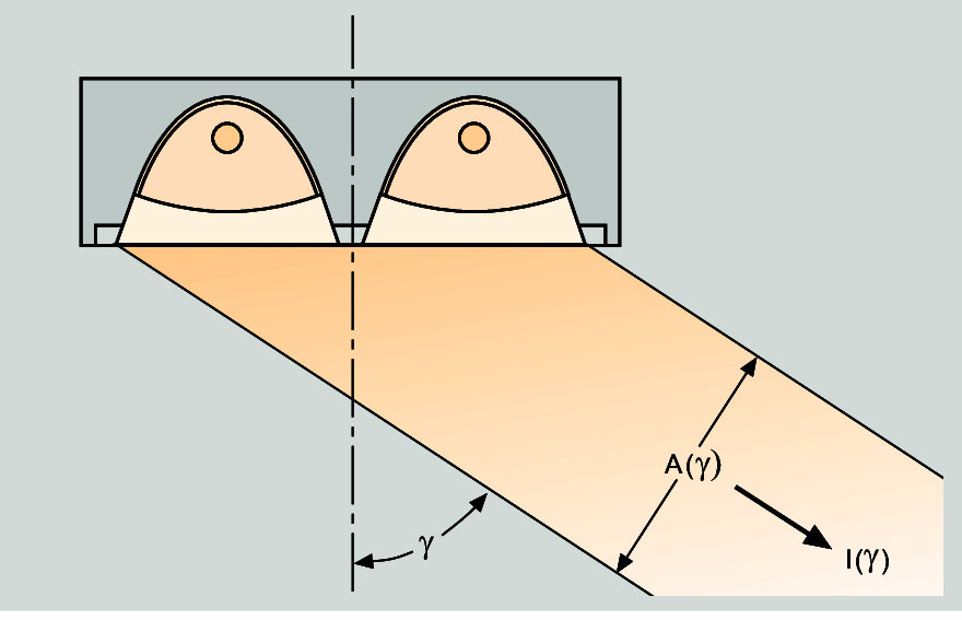
Definition of Mean Luminance L(γ) = I(γ) / A(γ) source: Trilux
- Surface luminance visible from different angles
- important for the determination of glare characteristics
- Luminance distribution is measured at 15° angles around the luminaire
Melanopic efficiency of Light
source: Trilux - Melanopic efficiency of light
- based on the human reception of light and colors
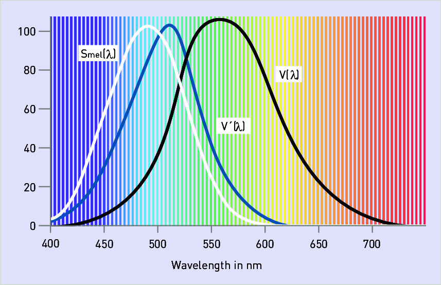
Luminous efficiency V(λ) for the eye adapted to light (photopic vision) and V’(λ) for the eye adapted to darkness (scotopic vision) as well as the melanopic efficiency function Smel for circadian rhythms
- \(S_{mel}\) controls our body's natural 24h cycle
- direction and spatial distribution of the light also play a role in this
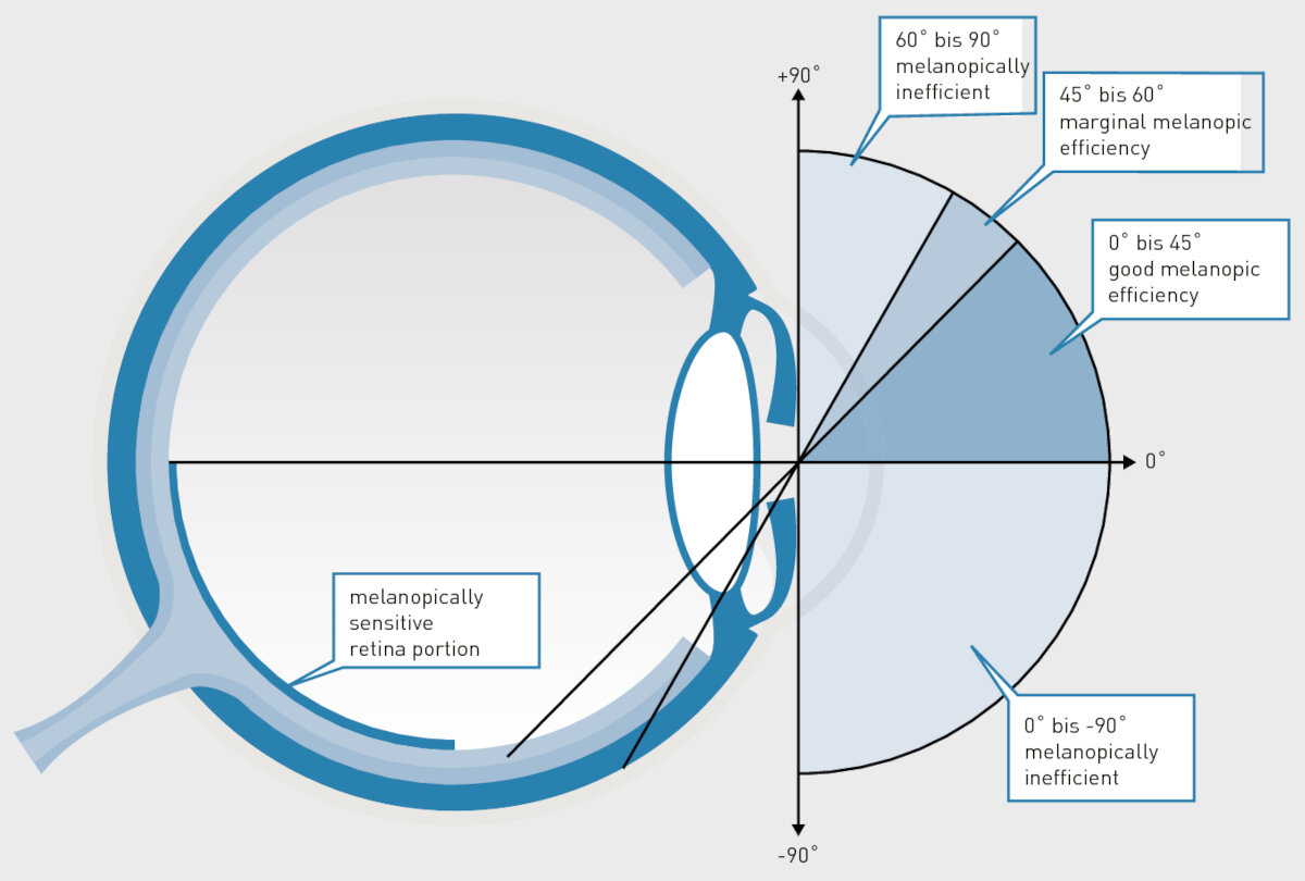
The melanopic efficiency of light depends on the light’s angle of incidence and the surface dimension of the light source.
IOR - Index of Refraction
Software Tools
Most of the software listed below is Windows-only, which is why I decided to install Windows 11 in a VM using UTM. I followed the UTM - Win11 install Guide
Blender
Blender has a Plugin called Luxrender 4.2.9 Blender with LuxCore 2.10.0-rc
Raychaser
GitHub
simple software for visualizing light beams on mirrors or lenses
Lambda Research Corporation
RayViz
- Add-In for Solidworks
- not available as a student trial
OSLO - Optics software for Layout and Optimization
- command line interface
- fully compatible with C code
- tolerance analysis
TracePro
Ansys - Zemax OpticStudio
- Free Trial available
- Student version available
Synopsys - CodeV
- Student version via email question
FreeCAD OpticsWorkbench
- limited
- probably with fewer and easier features
Synopsys - Light Tools
Recommendations of the University's Lighting Technology department
Relux
Recommendations of the University's Lighting Technology department - easy operation - good for basic simulations - calculates a lux table based on 'measurements'
Ansys - Speos
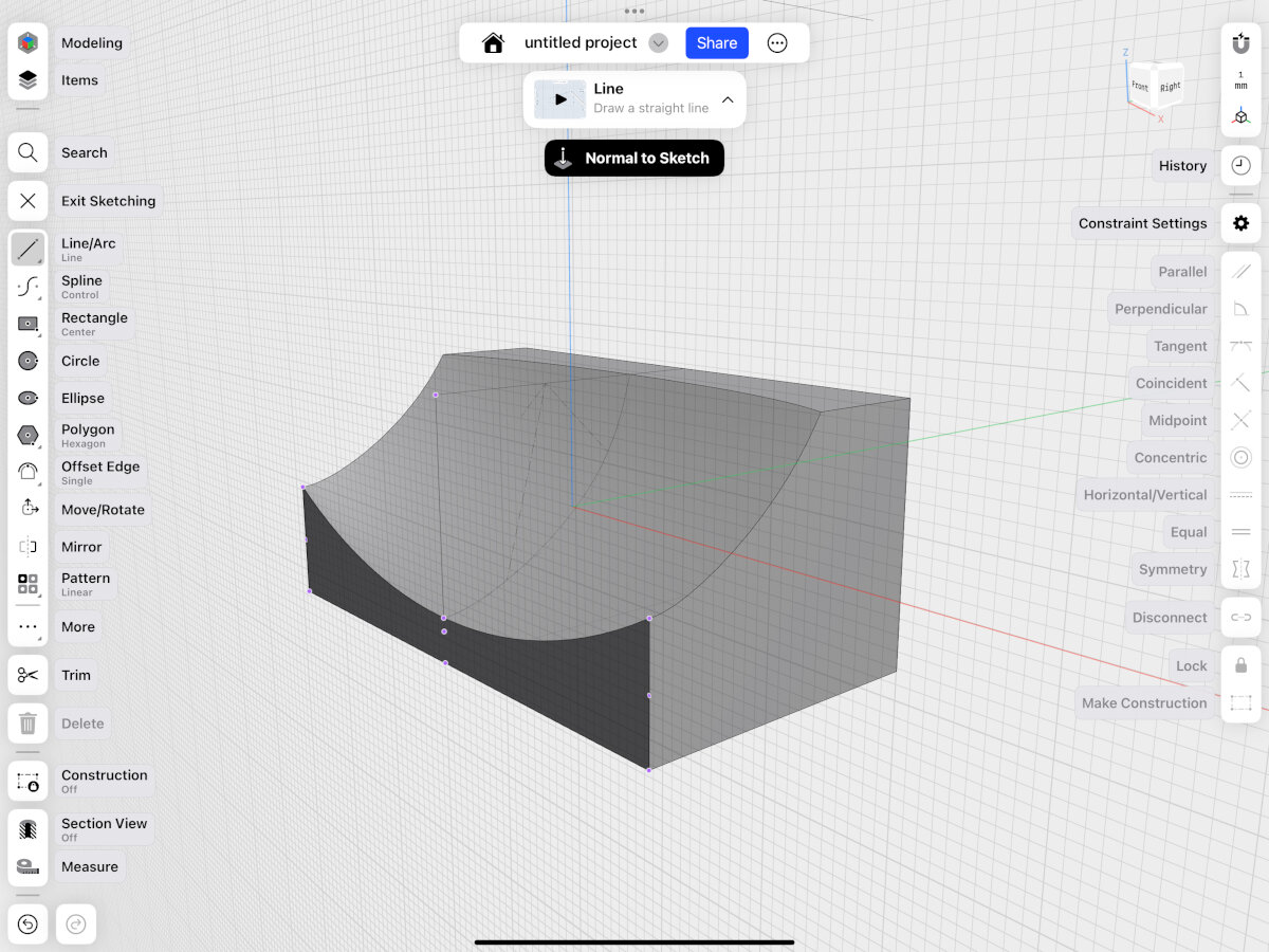
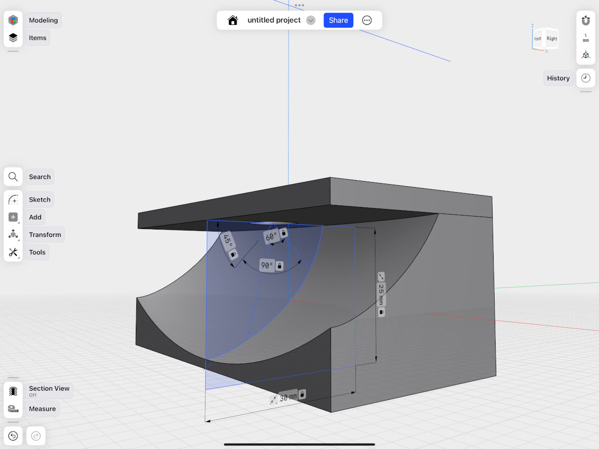
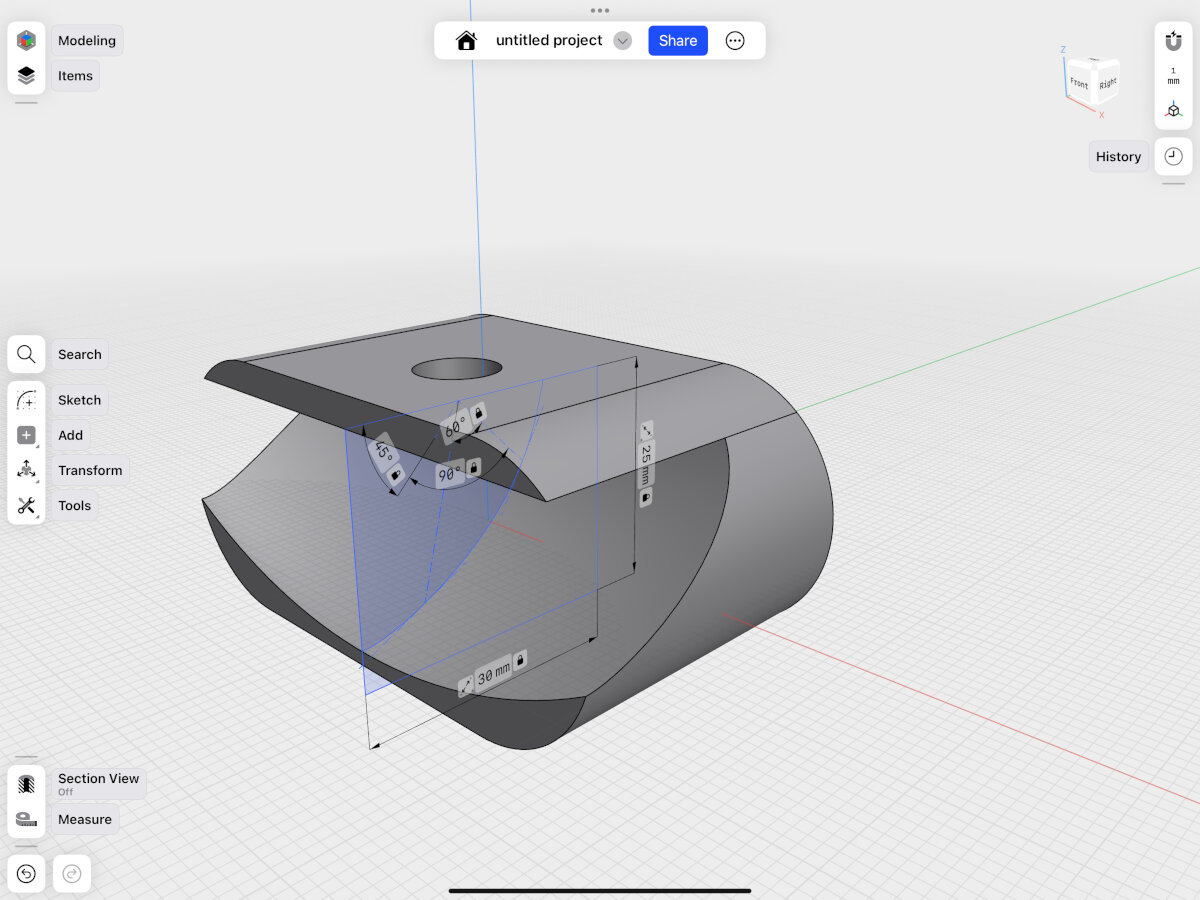
Modeling the Reflector
The reflector was modeled first as a mockup in Shapr3D to be later exported as an .stl for simulation purposes in Relux. Both steps need to be iterative to come up with a working design.
Design File (.shapr): Reflector Mockup V1
Design File (.step): Reflector Mockup V1
Simulating the Reflector
For simulating the reflector I tried out two tools: Blender (LuxCoreRenderer) and Relux. After a couple of days with Blender I decided to use Relux. In Blender I couldn't find an option on how to measure light intensity in a spot. There seems to be a way to use fake colors as an indicator for light intensity and the ability to export luminance on a surface to a spreadsheet, but I couldn't get it to work, which is why I switched to reliable and known software from the lighting industry: Relux.
Blender (LuxCoreRenderer)
Blender was only used for trial purposes and was not the final simulation software!
I followed this basic tutorial for free optics simulation in Blender
Warning
Save your files as you go, the program crashes once in a while and has no autosave function!
Design File (.blend): Tutorial
Design File (.blend): Reflector Simulation
Design File (.blend): IES Files Simulation
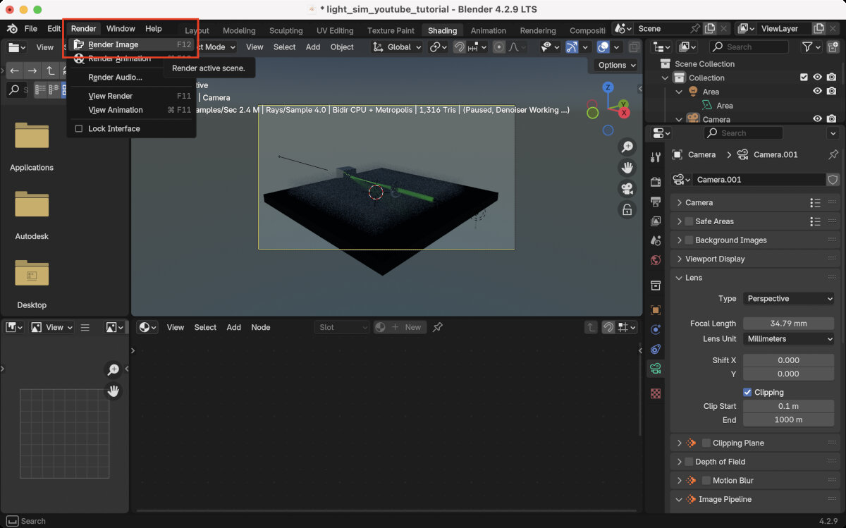
First Rendering
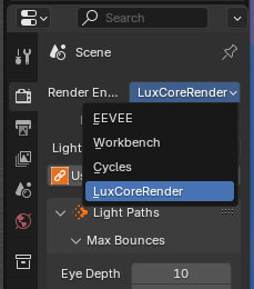
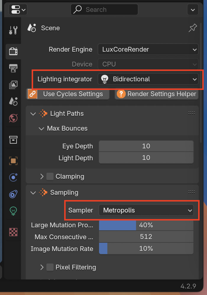
- Activate LuxCoreRenderer in the rendering setting
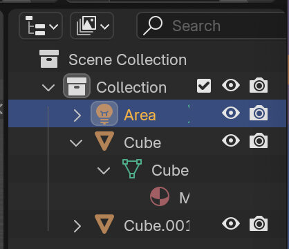
- Select Area light
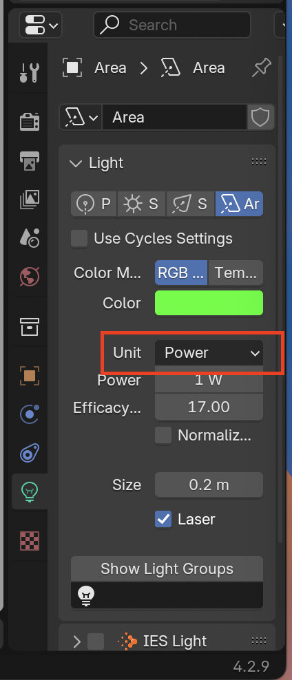
- Change light source to laser and set unit to 'Power' or 'Lumen'
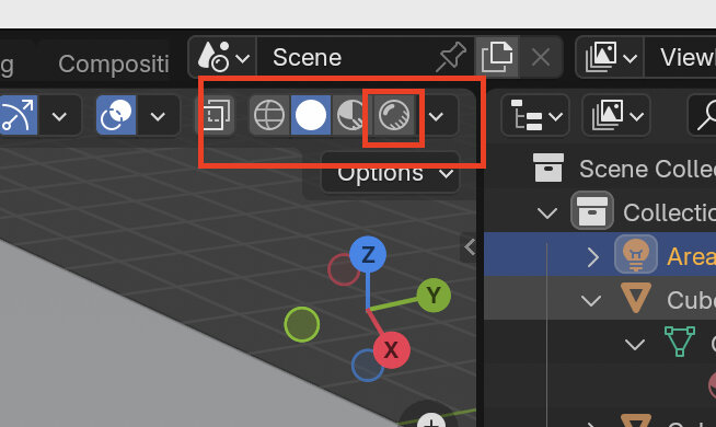
- Change view to 'Renderer'
- Decrease viewport rendering resolution to speed up rendering
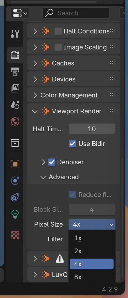
- Change 'Lighting Integrator' and 'Sampler' to speed up rendering
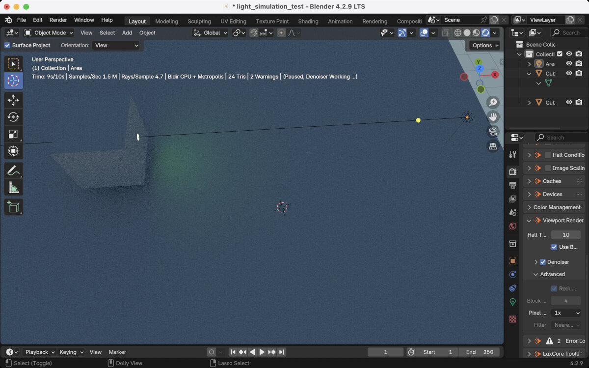
First result with LuxCore renderer
Adding optical components, simulating glass
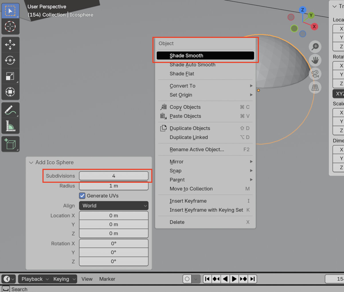
- Add a sphere to the area
- change the subdivision modifier to 4 to enable a smoother surface
- enable shade smooth
- Flatten the sphere to create a simple lens
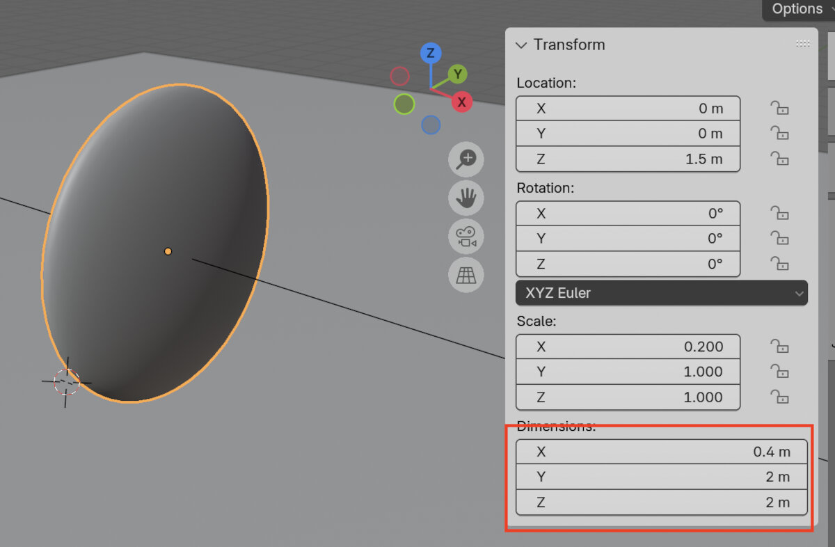
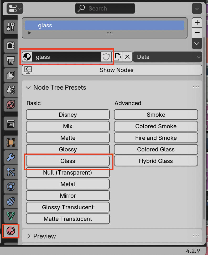
- Create a glass material under the material tab, assign with the button the 'Glass' preset to the new material.
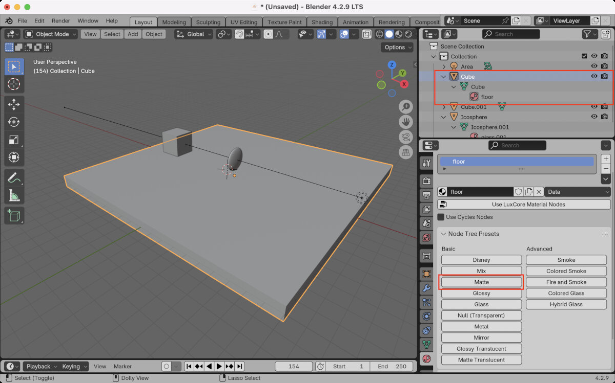
- Create a new matte material for the floor
- Switch workspace to 'Shading'
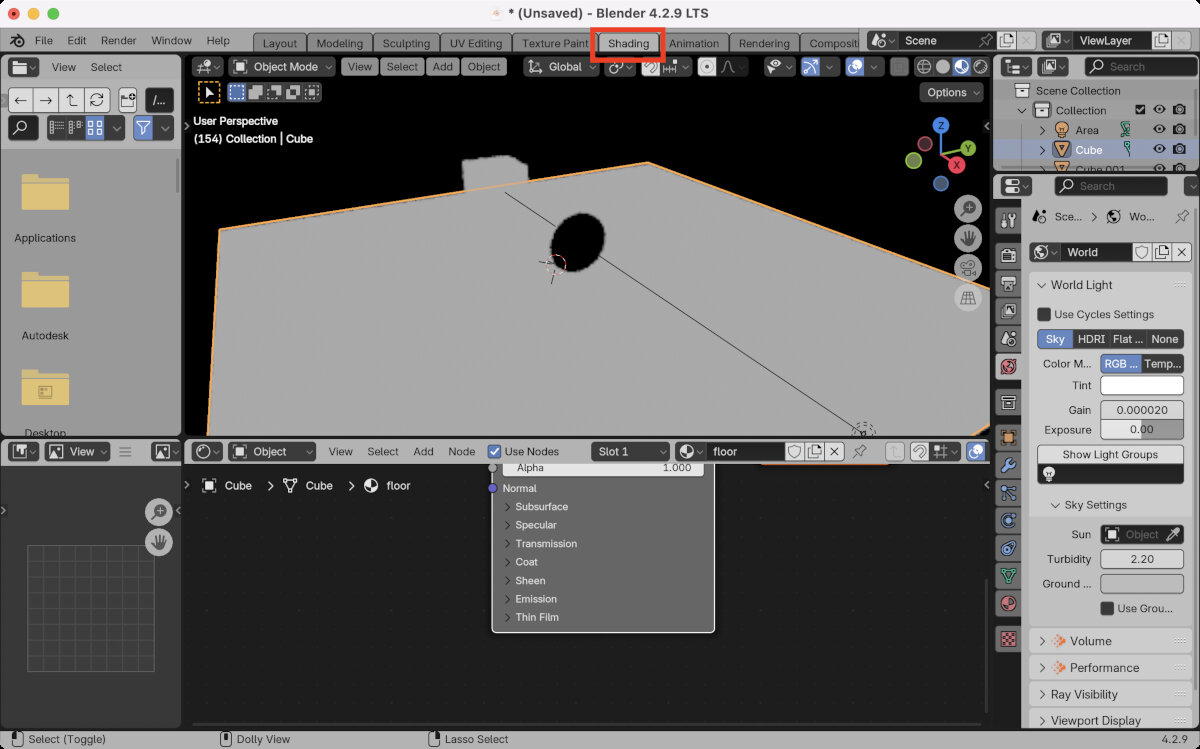
- Show Nodes
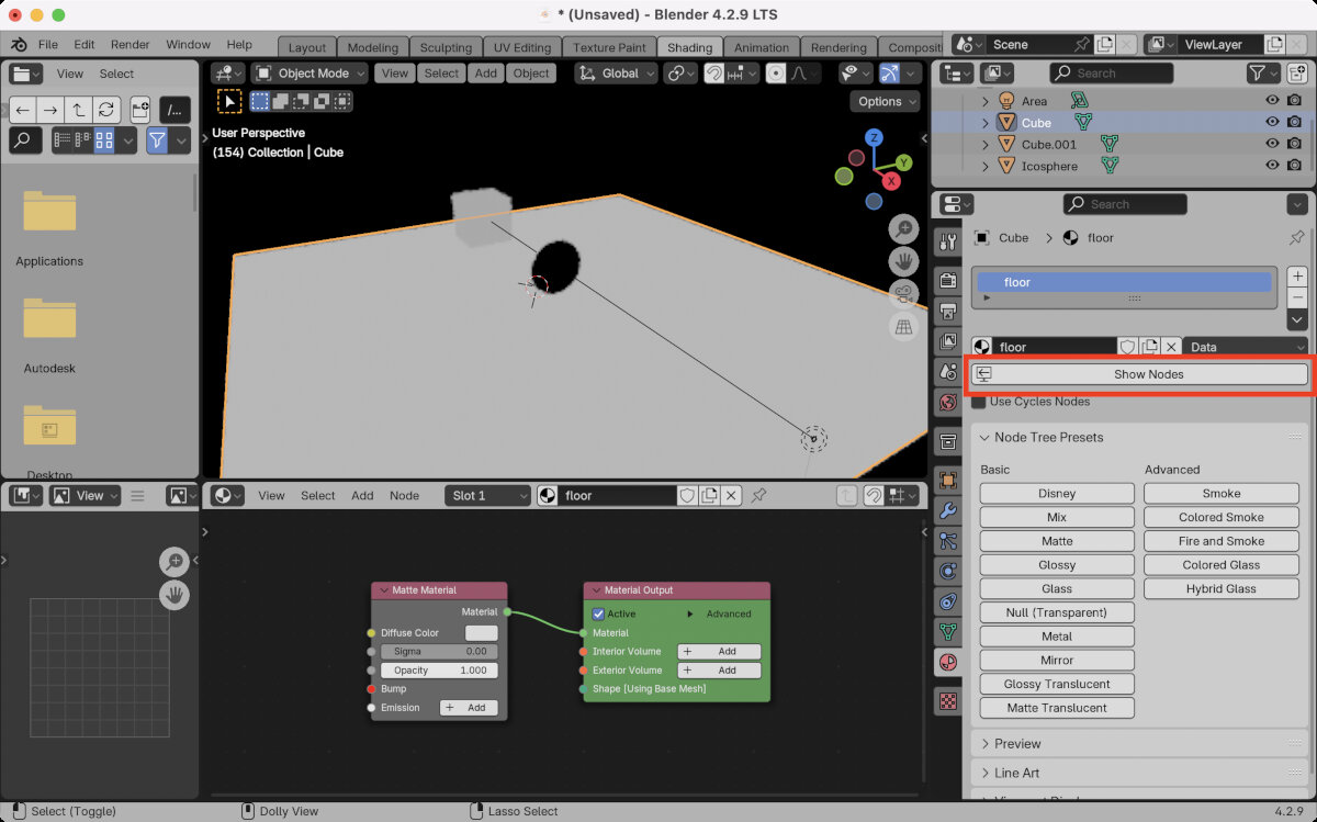
- Change color to grey to ease visibility of light
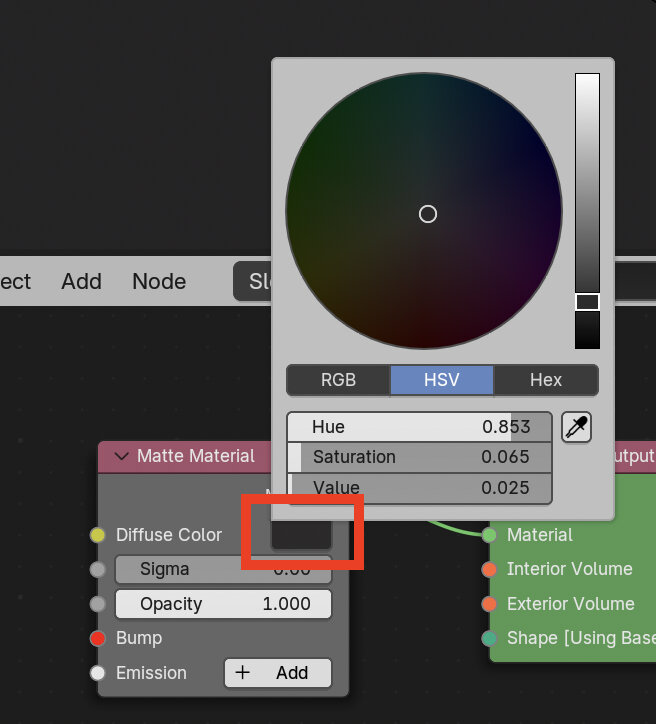
- Optionally you can change the 'value' which is the refractive index (not that useful for a matte floor material)
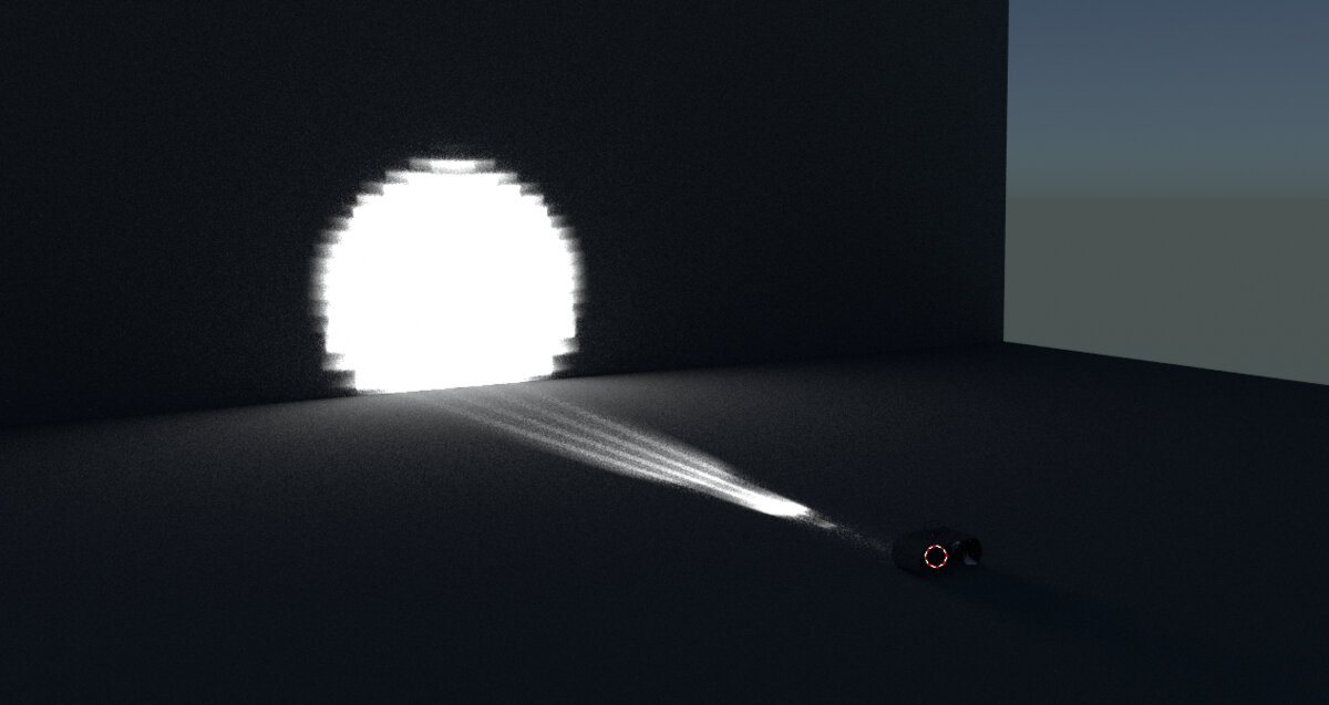
Creating fog, make light beams visible
- Go Back to the 'Layout' workspace and create a fog volume
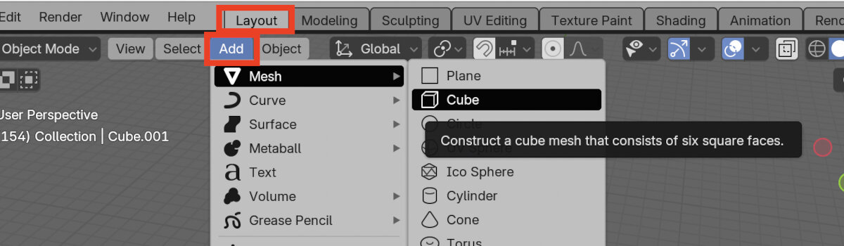
- Assign the 'Null (Transparent)' Material to the volume
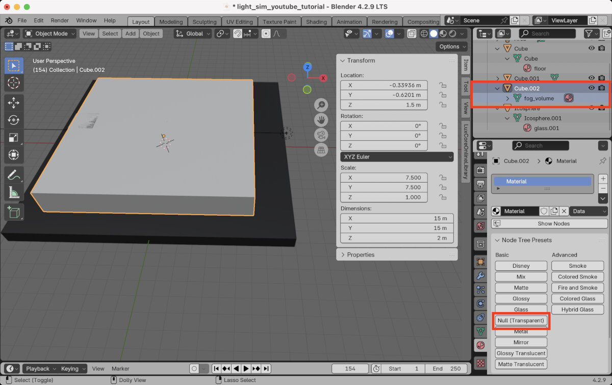
- In the 'Shading' workspace, rename the material and show the nodes
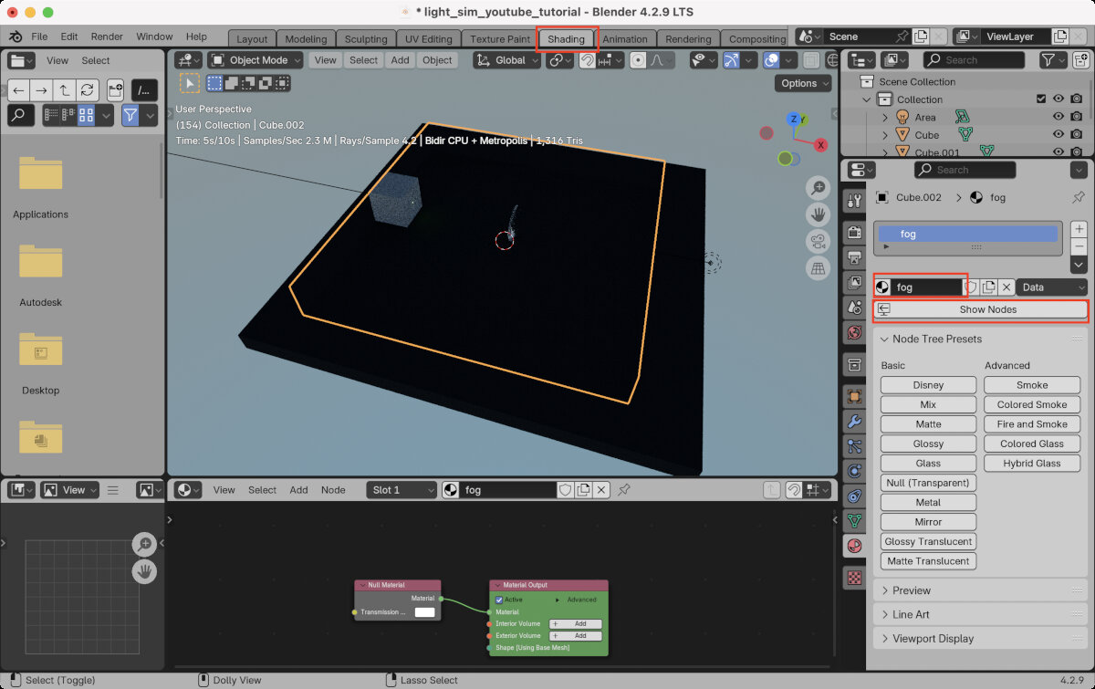
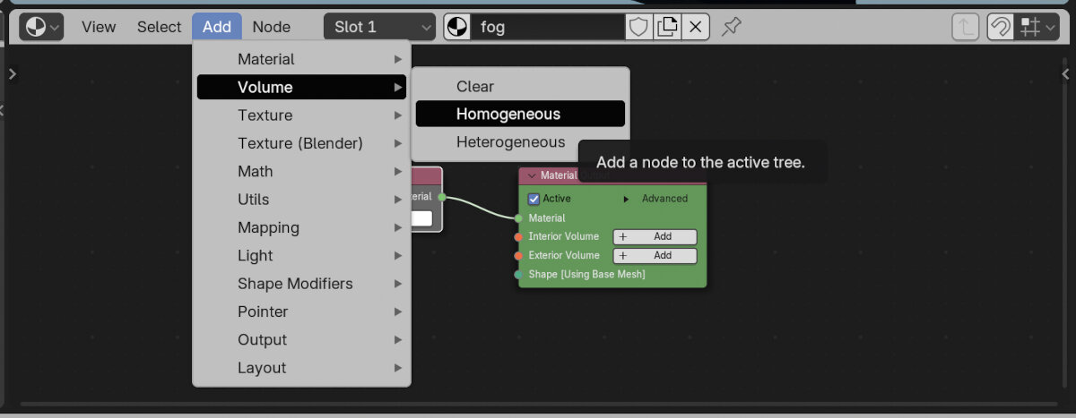
- In the Nodes area add a homogeneous volume
- Connect the volume to the interior volume
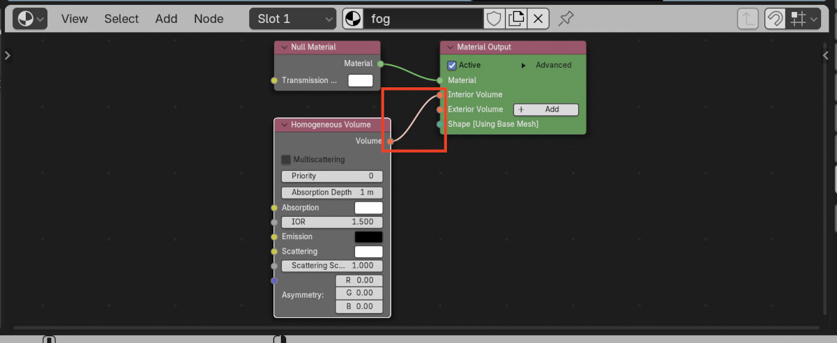
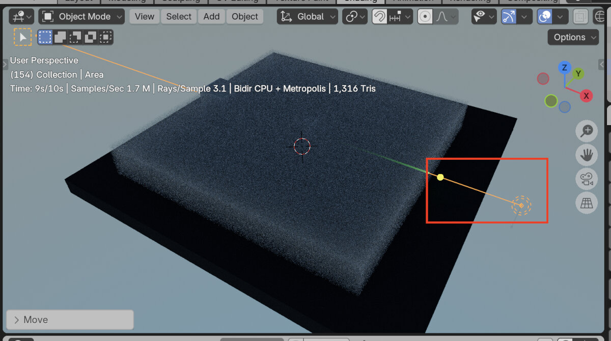
- Make sure the light source is positioned outside of the fog volume
- For the fog volume: reduce scattering to enable 'longer' visible rays in the fog
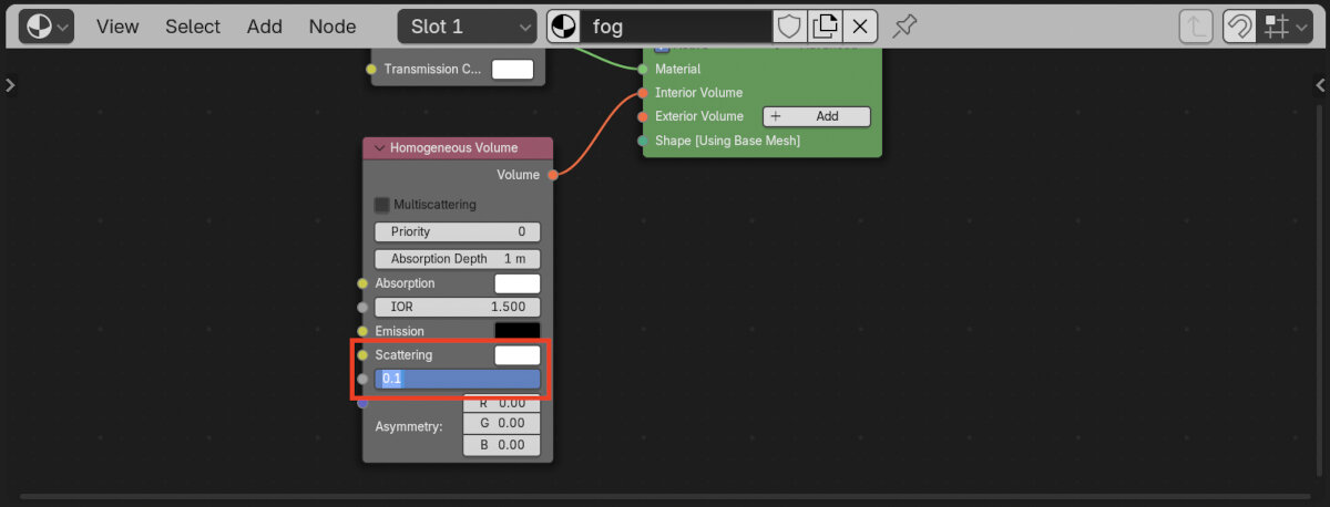
- Set index of refraction to the value for air: 1
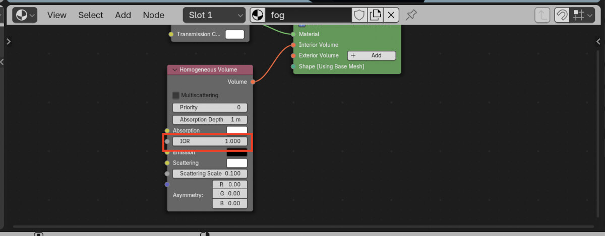
- Here I changed the laser diameter to 0.5m to enhance the visibility of refraction on the lens
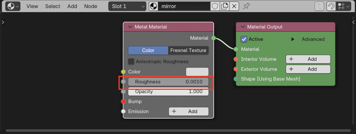
Mirror Materials
- Rotate (key 'R') the cube slightly around the z axis
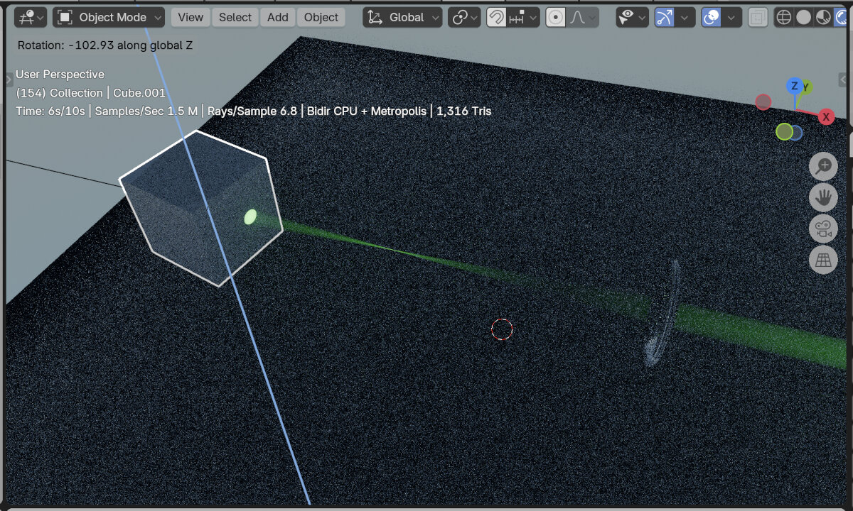
- Change material to 'Metal' and rename the cube to mirror
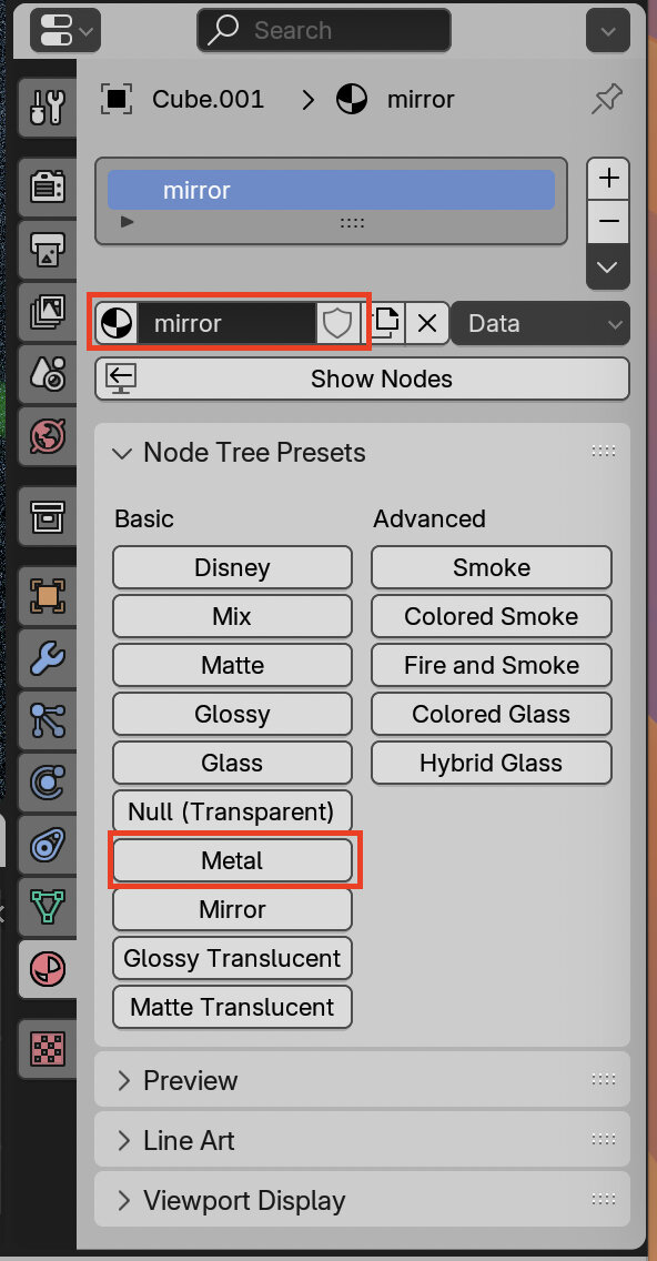
- Set the material roughness to 0 (will automatically change to 0.001)
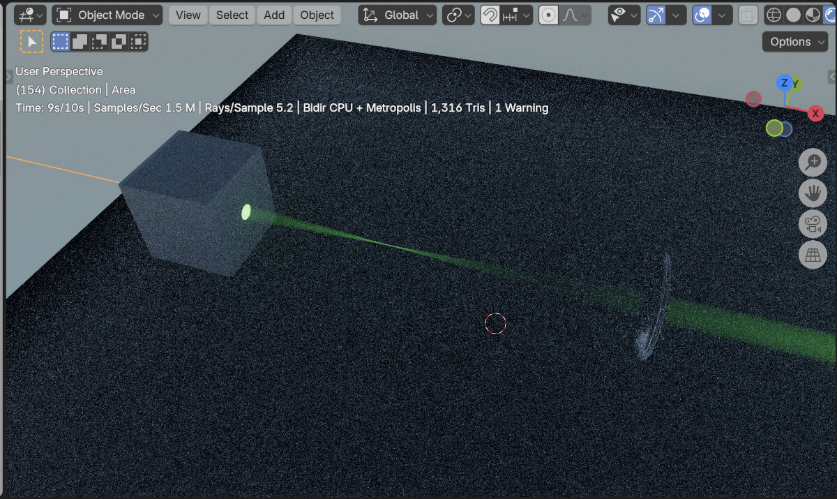
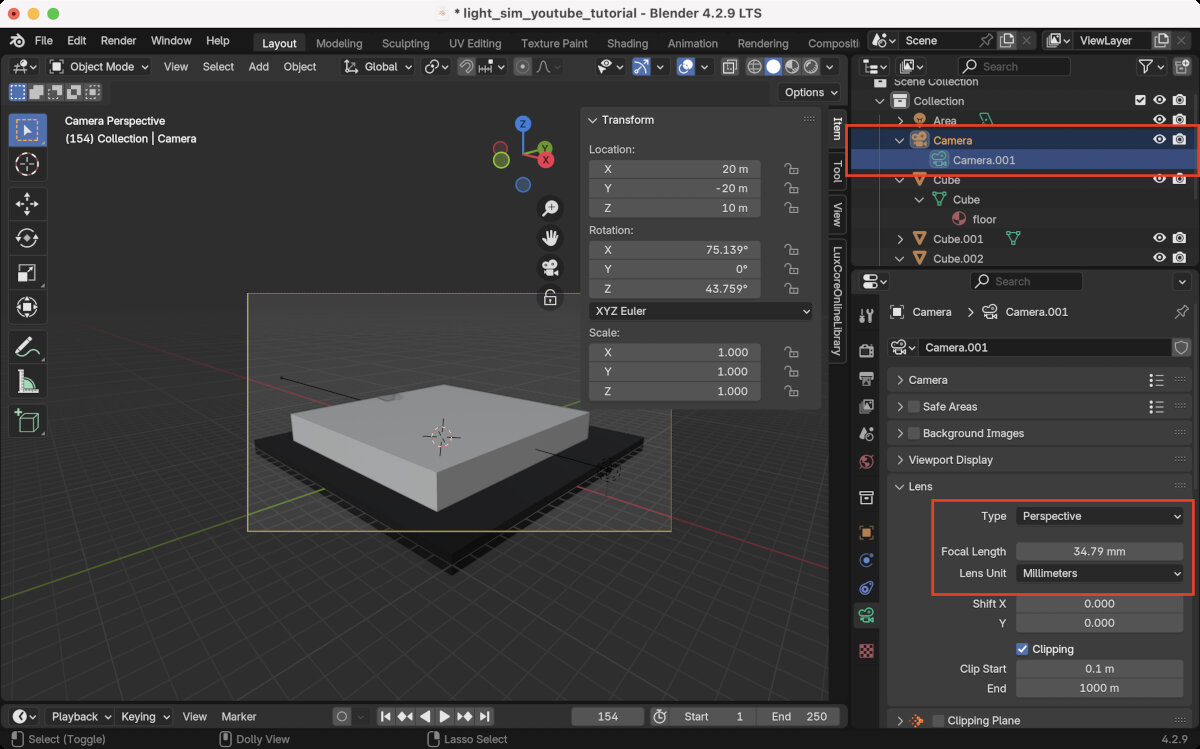
Render
- Add a camera and light to the scene

- Position the camera with the numeric transform window
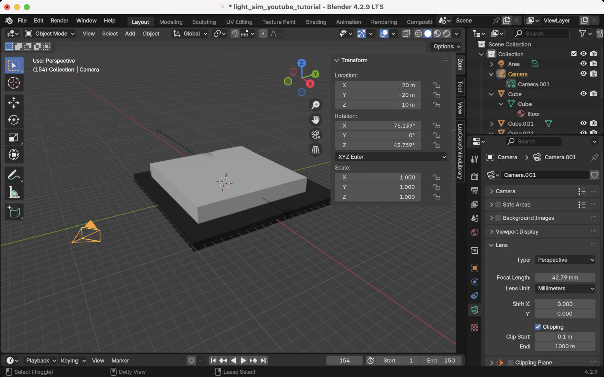
- Toggle camera view to see what the camera sees

- Adjust the settings in the camera side panel until the desired setting is reached. When the camera is too close, it starts to clip, which means no image is visible anymore because you are too close or inside an object.
- SAVE THE FILE! During rendering my computer often crashed.
- Render the scene with the Renderer
Here is the scene with a quick version 1 mockup that I built in Shapr3D.
Working Light Distribution Files
IES - Illuminating Engineering Society
The IES format is a file format for photometric data that helps to simulate and reproduce reflection in CAD setups.
To get some real world examples I downloaded some .ies files from LEDiL, specifically:
- C12469_LISA2-R-PIN with the CREE XD 16 LEDs
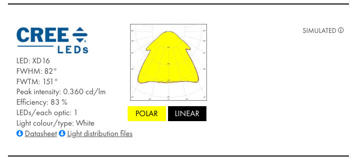
C12469_LISA2-R-PIN_(Cree_XD16)_SIMULATED.IES - C19761_STRADA-2X2R-T2
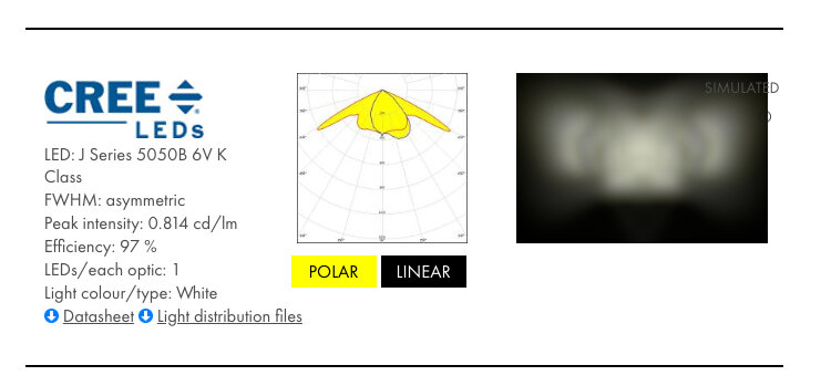
C19761_STRADA-2X2-5050-T2-R_011-JR5050-6V-K-5000K_10000000Rays_ZEMAX_glass_Simulated.ies
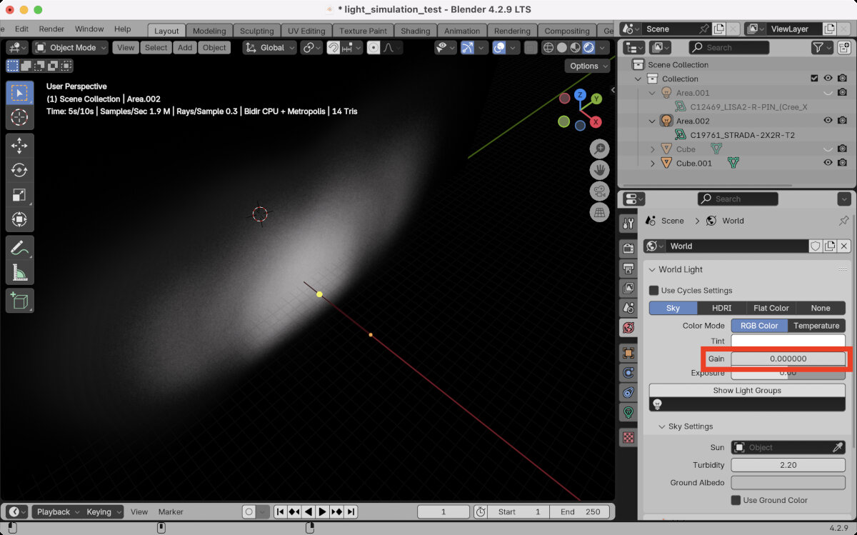
- Place a new 'Area' Light and load the IES file.
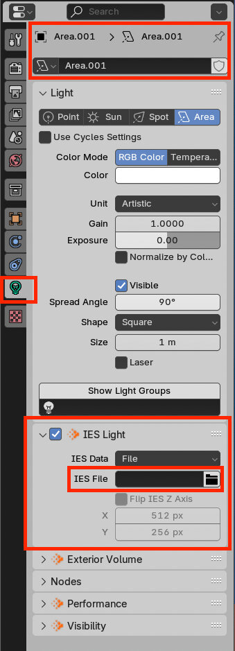
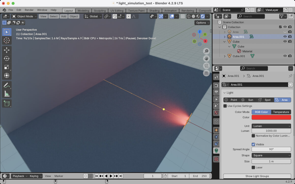
- Change the unit to 'Lumen' and set it to 1000.
- Change color to 'red' to ease visibility in the first place.
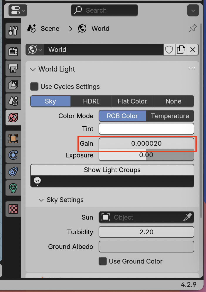
- Switch off the surrounding light! By default the background of the scene emits light to enable general object visibility. In this case, we want to disable this in order to identify changes between different light distribution curves.
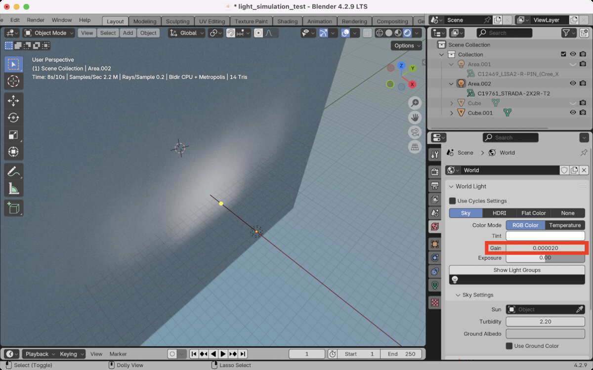
After the first success, I switched to a different light distribution curve just to make sure the simulation works and I compared the above mentioned STRADA and LISA2 .ies files. - After some deeper research (YouTube videos, Reddit, Google) and questions to ChatGPT, I decided to ditch the idea of creating my simulation in Blender due to low accuracy and lack of skill to handle the program on my side.
The biggest problem was that I couldn't get an accurate measurement of lux at a certain point. There seems to be a way with AOVs in LuxCore renderer and later exporting the data and analyzing it with Python.
Relux Desktop
Relux is a free software which allows the user to simulate light reflection and measure the light intensity in certain spots. Relux supports the import of .ies or .ldt files.
First Trials
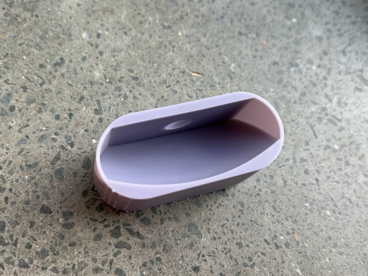
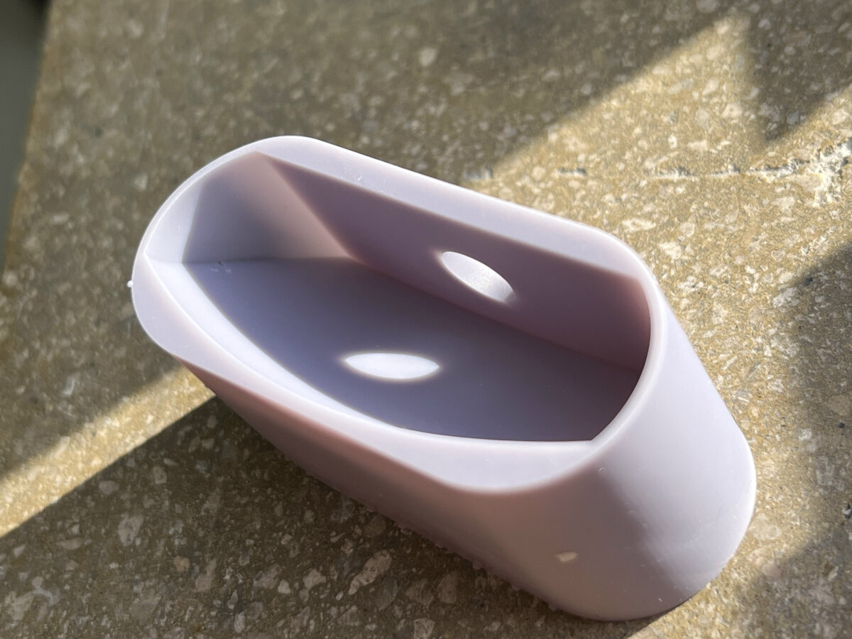
For testing purposes I imported my reflector mockup as an .obj file into Relux and upscaled the reflector 50x to use a normal wall light instead of a tiny SMD LED as a light source.
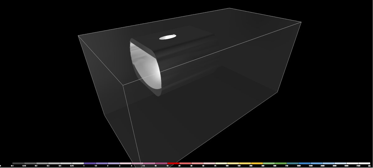
This is the "3D Luminance" output
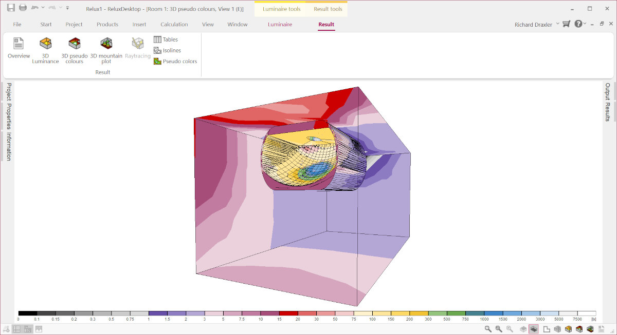
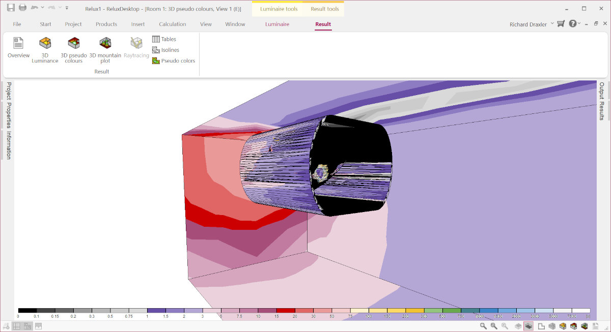
In these colorful visual diagrams the "3D pseudo colors" show the lux value represented as a separate color.
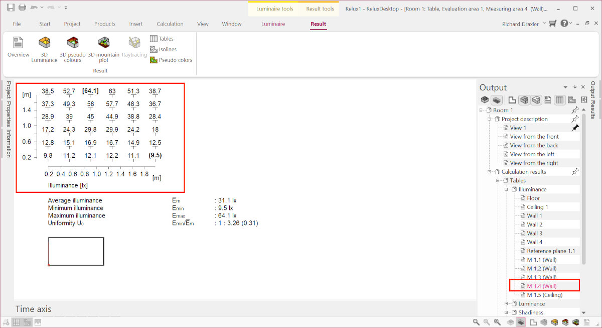
The same information but with more accurate lx numbers can be found in the "Results" tab.
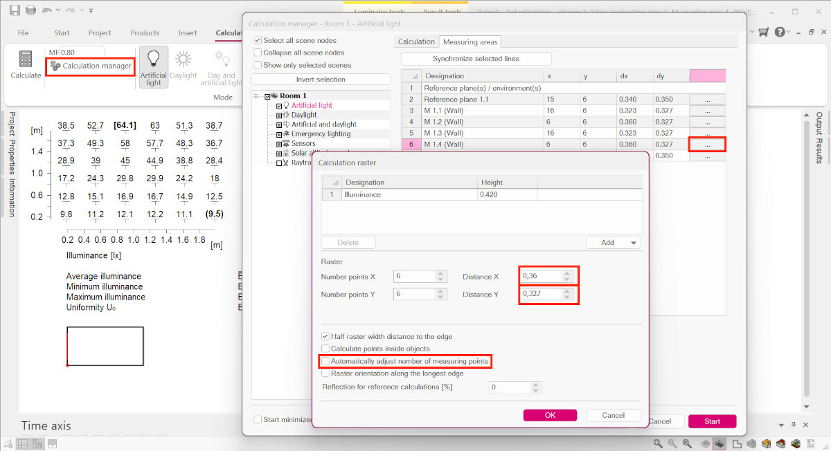
To increase the number of measurement points I disabled the automatic mode.
Due to time constraints I decided to keep the design as is and keep the improvement part for later. That is the reason why I did not iterate the design further.
Printing the Reflector (SLA Resin Printing)
The SLA printing setup and process can be found in Week 05 - 3D Scanning and Printing, SLA - Resin 3D printing
Electroplating the Reflector
Material for Electroplating
Items we needed to buy:
Items we already had in our Lab:
- Power supply
- degrease
- plastic containers
- non woven material (coffee filters)(maybe from the library)
Preparation for Electroplating
For any galvanic process the parts need to be conductive. That's why Ferdi bought graphite spray to cover the parts before electroplating them.
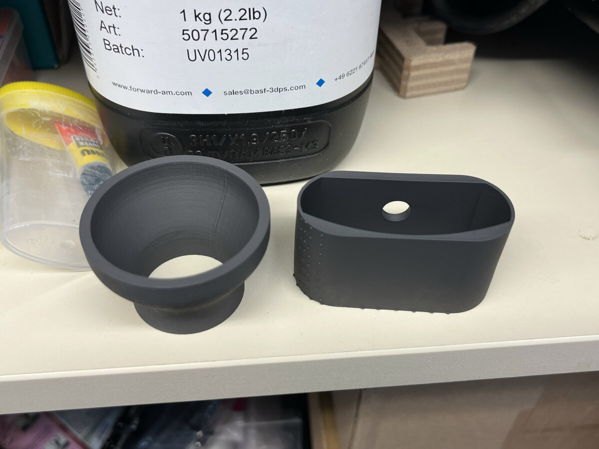
After spray painting the part with graphite I needed to measure the surface area which is covered in graphite. Since I only covered the relevant surface and the sides I only took some of the faces.
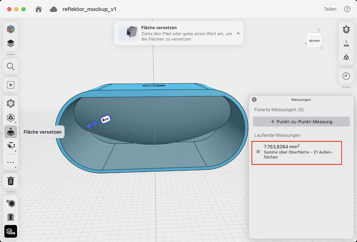
A = 8000 \(mm^2\)
A = 0.8 \(dm^2\)
Electroplating Process
For the electroplating process we cooperated with our university's department of electrochemistry and Electroplating Technology (Fachgebiet Elektrochemie und Galvanotechnik)
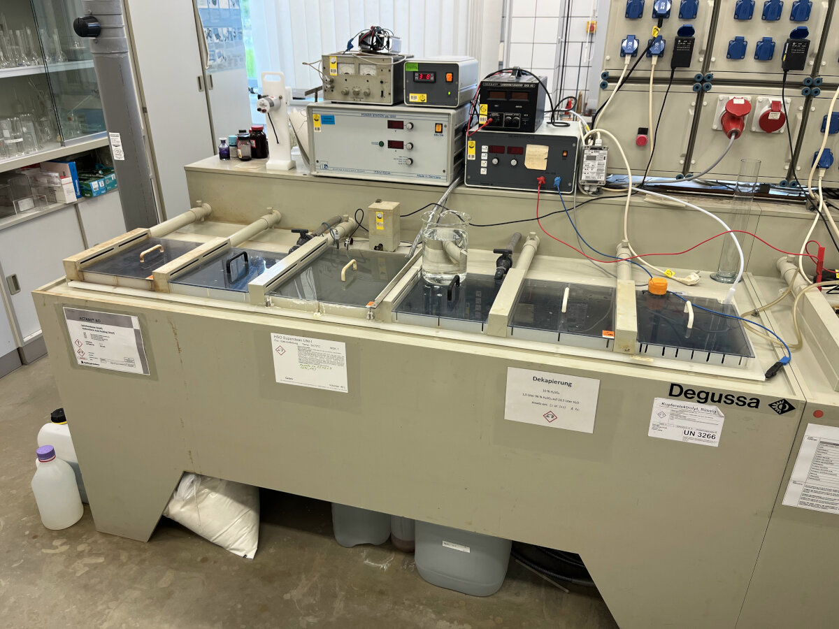
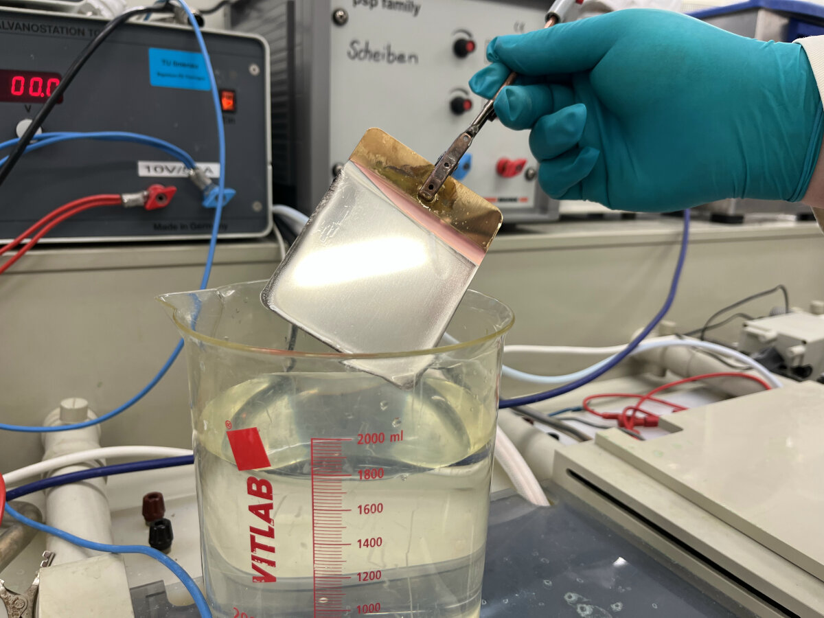
General setup used for the process.
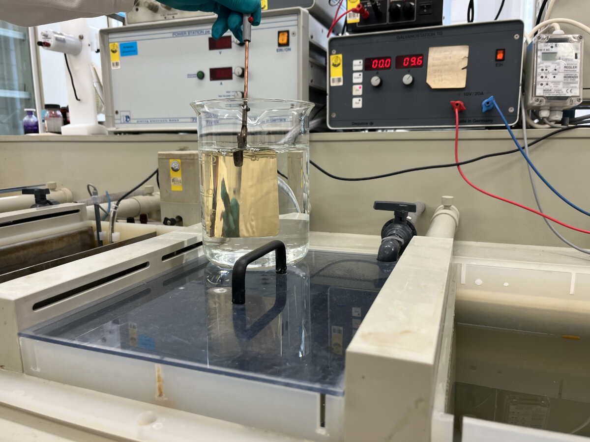
Cleaning the brass sample piece.
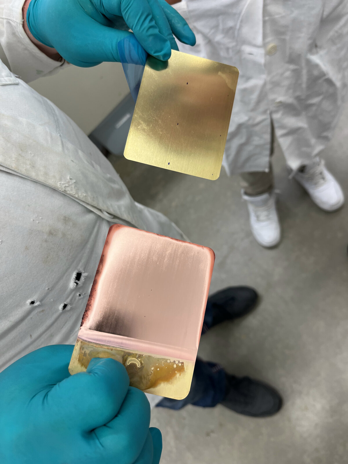
Left: already plated sample; Right: bare brass sample for comparison. First plating the brass sheet with copper. The dark edges resulted from a too high electroplating current.
Second layer with nickel on top of the first copper layer.
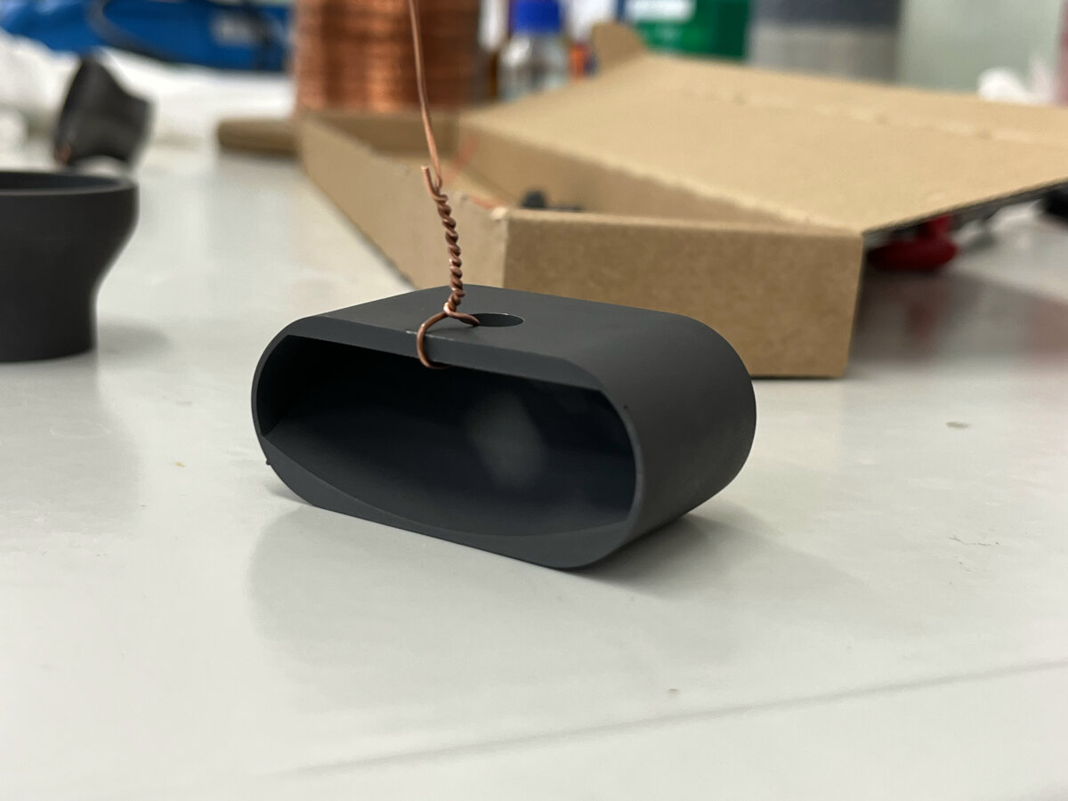
Finished and with graphite covered SLA 3D printed reflector.
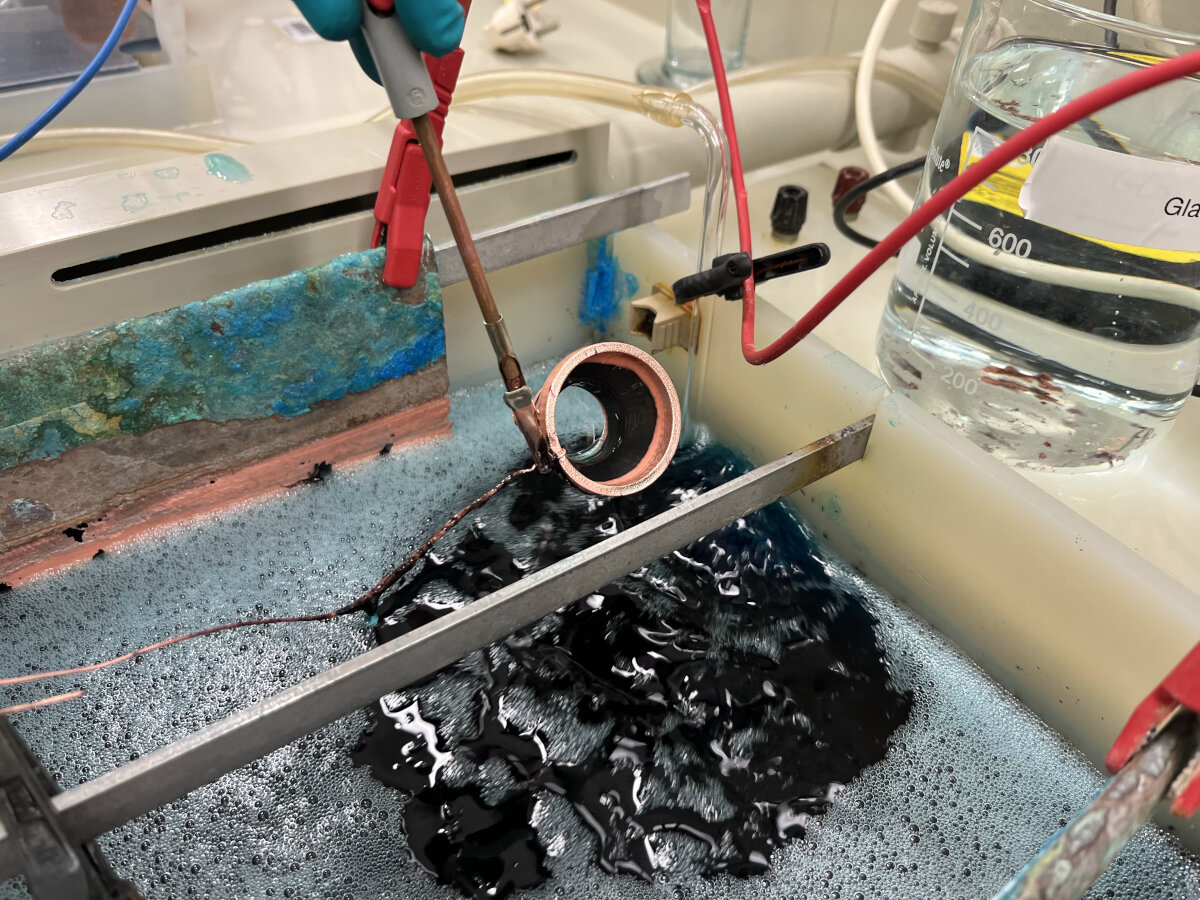
First try to electroplate a FDM printed part with copper. It is visible that the part was just plated partially because the conductivity of the graphite spray was too low.
To increase the conductivity of the graphite spray it is recommended to polish the parts before plating them. During the polishing process the particles on the surface get pressed together resulting in a lower resistance and therefore a higher conductivity. Unfortunately polishing the parts with a rotary polishing machine did not go as planned ...
Leftover parts after polishing the reflector. The SLA material is too brittle to withstand the force caused by the polishing process. The process continued with the copper wire attached, even after the part had been lost.
Final result of the electroplating process with copper. The part might be lost, but the resulting surface looks promising nevertheless.
The final part of a group member (Jarni). The surface is wrinkly since the graphite spray was not fully dried for 24h, therefore the graphite was not adhering to the surface of the plastic.
The final part of a group member (Benedikt). Right: Nickel covered part, previously covered in copper as a base layer; Left: copper plated part, without additional nickel layer. These are the best results we got during the first attempt electroplating FDM parts.
Procedure of Electroplating, Additional Links
Prusa - Guide
Formlabs - Guide
Youtube Channel
Tutorial Hen3DRIK
© 2026 Richard Draxler – Creative Commons Attribution Non Commercial
Source code hosted at gitlab.fabcloud.org